


Optical Modules: 400G, 800G, 1.6T, and PCB Selection in Manufacturing
Optical modules are critical components in modern communication systems, acting as the bridge between electrical and optical signals. In simple terms, they convert electrical signals from devices like routers, switches, and servers into light signals that travel through fiber optic cables. On the receiving end, they convert the light signals back into electrical signals that the devices can understand. This process is essential for enabling high-speed data transmission over long distances, such as in data centers and large-scale network infrastructures.
As technology advances, the speed and capability of optical modules have dramatically increased. Initially, optical modules operated at speeds of 10G, then moved to 40G and 100G. Today, optical modules are reaching speeds of 400G, with future technologies pushing towards 800G and even 1.6T (terabit). These advancements are driven by the growing demand for higher bandwidth to support data-heavy applications like AI, cloud computing, and real-time data processing. The transition from 400G to 1.6T represents a significant leap in data transmission, offering faster speeds, lower latency, and increased energy efficiency, which are essential for meeting the needs of the rapidly expanding digital world.
What is an Optical Module?
An optical module is a device that converts electrical signals into optical signals and vice versa in fiber optic communication. In simpler terms, it acts as a "translator" between the electrical world of computers, routers, and switches, and the optical world of fiber optics. When data is sent, the optical module converts the electrical signals from devices into light signals that travel through fiber optic cables. On the receiving end, the optical module converts light signals back into electrical signals that devices can understand and process. This two-way process of transmitting and receiving signals makes optical modules essential for high-speed data communication across long distances, especially in modern networks like data centers and telecommunications.
Key Components of Optical Modules
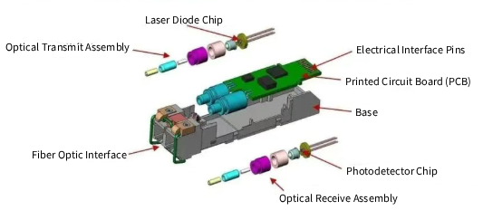
Optical modules consist of several key components that work together to ensure efficient signal conversion. The optical transmitter is the part that converts the electrical signal into an optical signal. It typically uses a laser or LED to generate light, which is then sent through the fiber optic cable. On the receiving side, the optical receiver detects the incoming light signals and converts them back into electrical signals. Finally, the electrical interface connects the optical module to the device (like a switch, router, or server), allowing the signals to be processed. These components work together to ensure fast, reliable data transmission over fiber optics, supporting everything from basic internet browsing to advanced AI and cloud computing applications.
Why Optical Modules are Crucial
Optical modules are vital because they enable high-speed data transmission over long distances in modern communication networks. Unlike electrical cables, fiber optic cables can carry data over much longer distances without signal degradation, making them ideal for connecting large data centers or wide-area networks (WANs). Without optical modules, it would be impossible to transmit data at the high speeds required by today’s technologies, such as video streaming, cloud storage, and artificial intelligence. As network speeds continue to increase, optical modules are essential for handling the vast amounts of data moving through global networks, ensuring that everything from online shopping to real-time data processing remains fast, efficient, and reliable. For example, modern data centers use optical modules to connect servers, enabling them to share massive amounts of data quickly, a necessity for applications like machine learning and real-time analytics.
What Are the Different Types of Optical Modules?
Optical modules come in various types, each designed to meet specific speed and performance requirements. These types are categorized mainly based on their form factor (physical size and shape), speed, and the application they are used for.
How Are Optical Modules Categorized Based on Form Factor?
SFP / SFP+ / SFP28 / SFP56
Speed: These modules cover speeds from 1.25G to 50G.
Applications: Commonly used in server NICs, access layer switches, and aggregation switches. These are some of the most widely used modules due to their small form factor and flexibility. SFP+ and SFP28 are often used for connecting servers and networking devices in smaller network environments or at the access layer of larger networks.
QSFP / QSFP+ / QSFP28 / QSFP-DD / OSFP
Speed: These modules support much higher speeds, ranging from 40G to 800G/1.6T.
Applications: Primarily used in data center core switches and high-speed interconnects. These modules are suitable for large-scale networking, enabling high-speed, high-capacity data transmission between servers, storage devices, and switches. For example, QSFP28 is commonly used for 100G Ethernet connections, while QSFP-DD and OSFP are emerging solutions for 400G and 800G speeds.
CFP / CFP2 / CFP4 / CFP8
Speed: These modules range from 100G to 400G.
Applications: They are designed for use in long-distance backbone networks and high-capacity transmission devices. CFP modules are typically used in high-speed, long-distance data center connections, supporting large-scale and high-bandwidth applications, such as internet backbones and high-capacity telecom systems.
XFP
Speed: The XFP module typically supports 10G speeds.
Applications: It was used in the early generation of 10G optical modules, though it has largely been replaced by newer, more efficient versions like SFP+. XFP is still found in older systems that require 10G speeds but is gradually being phased out as faster modules become more common.
SFP-DD
Speed: This newer form factor supports speeds from 50G to 200G.
Applications: It is primarily used in high-density, high-speed solutions for server access. SFP-DD (Double Density) modules are used in situations where higher bandwidth is needed but still within the compact size of the SFP family. They are useful in data centers and server farms where high throughput and density are critical.
Comparison Table
| Module Type | Speed Range | Typical Applications |
| SFP / SFP+ | 1.25G to 50G | Server NICs, access layer, aggregation switches |
| QSFP / QSFP+ | 40G to 400G | Data center core switches, high-speed interconnects |
| QSFP28 | 100G | Data centers, high-bandwidth applications |
| QSFP-DD / OSFP | 400G to 1.6T | High-capacity interconnects, future-proof networking |
| CFP | 100G to 400G | Backbone networks, telecom systems |
| XFP | 10G | Early-generation 10G applications |
| SFP-DD | 50G to 200G | High-density server access solutions |
What is the Role of Speed in Choosing Optical Modules?
The speed of an optical module is a crucial factor in determining its suitability for different applications. Speed influences both the data throughput and the overall performance of a network. Understanding the difference between electrical port rate and optical port rate, along with the impact of modulation techniques like PAM4, helps in selecting the right module.
Electrical Port Rate vs Optical Port Rate
The electrical port rate refers to the speed at which data is transmitted through the electrical signals from the device (such as a server or switch). This is often referred to as the "bit rate" and is typically measured in Gigabits per second (Gbps).
The optical port rate is the speed at which data is transmitted over the fiber optic cable, which may differ from the electrical port rate due to the nature of signal conversion. For example, in some cases, the electrical rate is higher than the optical rate because of the modulation techniques used.
What is PAM4 Modulation?
PAM4 (Pulse Amplitude Modulation 4) is a technique used to increase the data rate of optical modules without requiring additional bandwidth. Unlike traditional binary (2-level) modulation, PAM4 uses four levels of signal amplitude to represent two bits of data per symbol, effectively doubling the data rate for the same bandwidth.
For example, an optical module that uses PAM4 modulation can transmit 50 Gbps of data with a 25 Gbps electrical port rate. This is a significant advantage in achieving higher data rates without needing to expand the physical infrastructure, especially when upgrading to high-speed modules like 400G or 800G.
Impact of Modulation Techniques on Data Throughput
Different modulation techniques directly affect the data throughput of optical modules. Traditional modulation (like NRZ) sends one bit per signal, while more advanced methods like PAM4 send multiple bits per signal, increasing the data rate. Additionally, higher-order modulation techniques, such as PAM6 (which uses six levels), are also being researched and implemented for even faster transmission speeds, particularly in upcoming 1.6T optical modules. These advances allow networks to handle much more data without having to physically increase the number of transmission channels.
The adoption of these modulation methods is a key factor in the growing demand for higher-speed optical modules, from 100G and 400G to 800G and beyond, enabling the infrastructure needed to support technologies like AI, big data, and 5G networks.
What Do the Terms 400G, 800G, and 1.6T Mean in Optical Modules?
The terms 400G, 800G, and 1.6T refer to the total data transmission speeds of optical modules, which are essential for modern networks. These modules enable high-speed data transfer over long distances, particularly in data centers, telecom networks, and cloud computing environments. Understanding these terms is crucial for selecting the right optical modules to meet specific network needs.
What Does 400G Represent?
400G optical modules represent a data transmission rate of 400 gigabits per second (Gbps). This has become a standard for high-capacity networks, especially in data centers and telecommunications.
Formula: The 400G speed is achieved by using 8 channels, each transmitting 50G per channel. This means 8 separate data paths (channels) are used to achieve a total of 400G.
Example: 8 channels × 50G per channel = 400G.
Use Cases for 400G
400G optical modules are widely used in large data center cores and high-capacity interconnects. These networks need to handle large volumes of data quickly and efficiently. For example, global cloud service providers like Amazon Web Services (AWS) and Google use 400G optical modules to connect data centers around the world, ensuring that data can move quickly between locations with minimal latency. This makes 400G a standard choice for networks that require fast data transmission over long distances.
What Does 800G Represent?
800G optical modules refer to a data transmission rate of 800 gigabits per second, which is double the speed of 400G modules. As demand for faster, more efficient data processing grows, 800G has become an increasingly popular choice in modern networks.
Formula: 800G optical modules use 8 channels, each transmitting 100G per channel. This setup allows for higher data throughput and better utilization of the available bandwidth.
Example: 8 channels × 100G per channel = 800G.
Applications of 800G
800G modules are crucial for high-bandwidth, future-proof networks, which need to handle the massive amounts of data generated by new technologies like artificial intelligence (AI), machine learning, and 5G. These modules are particularly relevant for next-generation data centers, which require scalable, high-speed solutions to support intensive workloads like real-time analytics and large-scale data processing. Additionally, 800G modules help improve the performance of AI workloads, allowing for faster data access and processing, which is vital for AI-driven applications like image recognition and natural language processing.
What Does 1.6T Represent?
1.6T optical modules represent a data transmission rate of 1.6 terabits per second, or 1600 Gbps. This is one of the highest speeds achievable in optical modules and is designed for the most demanding applications.
Formula: 1.6T modules use 8 channels, each transmitting 200G per channel. This setup allows for extremely high data throughput, which is essential for future-proofing networks as data consumption continues to increase.
Example: 8 channels × 200G per channel = 1.6T.
Technological Challenges for 1.6T
While 1.6T modules offer incredibly high speeds, they also present several challenges. One of the biggest obstacles is the physical limits of fiber optic cables. As the speed of transmission increases, maintaining signal integrity over long distances becomes harder. Additionally, signal compensation techniques are required to ensure that data is transmitted without loss or corruption. To overcome these challenges, more advanced modulation techniques, such as PAM6 (Pulse Amplitude Modulation 6), are being used. PAM6 allows for even more data to be transmitted over the same bandwidth by using six signal levels, which significantly increases data rates. However, as with all new technologies, 1.6T optical modules are still in the early stages of development, and further advancements are needed to make them widely available.
Comparison Table
| Optical Module | Speed | Formula | Applications | Technological Challenges |
| 400G | 400 Gbps | 8 channels × 50G per channel = 400G | - Large data center cores - High-capacity interconnects - Telecom networks - Global cloud data transmission | - Signal integrity over long distances - Efficient use of bandwidth at high speeds |
| 800G | 800 Gbps | 8 channels × 100G per channel = 800G | - High-bandwidth, future-proof networks - AI-driven workloads - Next-gen data centers - Real-time analytics and data processing | - High signal loss and attenuation at extreme speeds - Requires advanced error correction and modulation techniques |
| 1.6T | 1.6 Tbps (1600 Gbps) | 8 channels × 200G per channel = 1.6T | - High-speed backbone networks - Telecom systems - Future-proofing large-scale networks - Cutting-edge AI and big data processing | - Physical limits of fiber optics - Signal compensation and advanced modulation (PAM6) for reliable transmission |
How Should PCB Design Be Chosen for Optical Module Manufacturing?
When designing PCBs for optical module manufacturing, several key factors must be considered to ensure optimal performance. The PCB plays a critical role in maintaining signal integrity and managing thermal dissipation. Choosing the right materials, such as Mirror Aluminum PCBs, and optimizing the layer structure and high-speed design requirements are essential for handling high-speed signals and heat in these advanced modules.
What is the Role of PCB in Optical Module Manufacturing?
Printed Circuit Boards (PCBs) are a fundamental component in the design and manufacturing of optical modules. They provide the physical platform for connecting electrical components, including the laser diodes, receivers, and electrical interfaces, that make up the optical module.
Signal Integrity
For high-speed optical modules, signal integrity is a critical concern. The signals sent through optical modules travel at high speeds, so it’s essential to manage how these signals are routed and processed on the PCB. Poor signal integrity can result in data loss or delays, leading to unreliable network performance. By optimizing the design of the PCB, such as by controlling the trace widths and ensuring proper grounding, manufacturers can ensure that signals remain clear and strong as they travel through the module.
Thermal Management
Another key role of the PCB is thermal management. As optical modules operate at high speeds, they generate significant heat. This heat must be dissipated effectively to prevent components from overheating and malfunctioning. Proper PCB design can integrate heat dissipation features such as copper layers for better thermal conductivity or the use of aluminum-based PCBs, which are particularly effective at managing heat in high-performance optical modules. Without proper thermal management, the longevity and efficiency of optical modules would be severely compromised.
What Are the Key Considerations for Choosing PCBs for Optical Modules?
When choosing a PCB for optical module manufacturing, several critical factors must be considered to ensure the module operates at peak performance.
Material Selection
The material of the PCB plays a significant role in the overall performance of the optical module. FR4 is the most common material used for general-purpose PCBs, but it’s not ideal for high-speed optical modules due to its relatively low thermal conductivity. For optical modules, aluminum-based PCBs, such as Mirror Aluminum PCBs, are a better choice. These materials offer superior heat dissipation and provide the ability to handle high-speed signal transmission without introducing excessive heat.
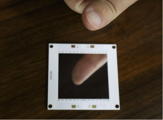
Mirror Aluminum PCB
Mirror Aluminum PCBs are especially beneficial for optical modules because they offer superior heat dissipation. This is crucial for optical modules, as high-speed data transmission generates significant heat. The aluminum base acts as a heat sink, ensuring the module doesn't overheat, which helps prevent performance degradation. Additionally, the reflective properties of this material enhance signal clarity and quality. For example, the high-quality mirror aluminum PCBs produced by PCBMASTER provide customized solutions specifically designed for optical module applications.
Layer Structure
For optical module PCBs, multi-layer designs are often used to enhance performance. Multi-layer PCBs allow for more effective signal routing, as they provide more surface area for traces while reducing the chances of interference from other components. Additionally, multi-layer PCBs help in reducing electromagnetic interference (EMI), ensuring that high-speed signals are not disrupted by noise from adjacent circuits. This results in a more stable and reliable optical module.
High-Speed Design Requirements
In optical modules, high-speed signal design is crucial for maintaining performance. Below are key considerations for ensuring signal integrity and low-latency communication:
Impedance Matching
Impedance matching is necessary to prevent signal reflection, which can cause data loss or transmission errors. By ensuring that the impedance of the signal trace on the PCB matches the impedance of the optical module's electrical components, manufacturers can minimize signal reflection and achieve stable, reliable data transfer.
Signal Trace Width and Via Design
The width of the signal traces on the PCB and the design of the vias (the holes that allow electrical signals to pass between layers) directly impact signal propagation. If traces are too wide or vias are poorly designed, it can result in signal distortion, affecting the overall speed and quality of the optical module. Proper trace width calculations and via design are essential to maintaining the desired signal integrity at high speeds.
Low-Latency Signal Propagation
In high-speed optical modules, latency must be minimized to ensure data is transmitted quickly. To achieve low-latency performance, optimized routing, proper trace lengths, and high-quality materials should be used to minimize delays and prevent signal degradation. Every aspect of the PCB design, from the materials used to the placement of components, should focus on maintaining low-latency signal propagation.
Conclusion
As optical module technology continues to evolve, the breakthroughs from 400G to 1.6T speeds are not only driving the progress of data centers and communication networks but also laying the foundation for the arrival of the AI and big data era. In this process, selecting the right PCB materials and designs is crucial to ensuring the performance of optical modules. With professional suppliers like PCBMASTER, we can access high-quality, customized PCB solutions that meet the stringent requirements for high-speed signal transmission and heat dissipation. Looking ahead, optical modules will continue to evolve toward higher speeds, lower latency, and stronger throughput, powering the global upgrade of network infrastructure. Whether it's the current 400G modules or the upcoming 800G and 1.6T modules, we are at the forefront of an exciting wave of technological innovation.
FAQs
1. What are the differences between SFP28 and QSFP28 modules?
| Feature | SFP28 | QSFP28 |
| Form Factor | Small form-factor pluggable (SFP) module designed for 25G speeds | Larger, high-density module designed for 100G speeds |
| Channel Count | Single channel, supporting 25G data rates | Four channels, each supporting 25G, totaling 100G |
| Applications | Server NICs, aggregation switches, access layer devices | Data center core switches, high-speed interconnects |
| Speed | Up to 25Gbps per channel | Up to 100Gbps (4x25G) |
2. How do optical modules achieve higher speeds with PAM4 modulation?
PAM4 (Pulse Amplitude Modulation 4-level) is a modulation technique that allows each signal symbol to represent 2 bits of data instead of the standard 1 bit. By encoding multiple bits per symbol, PAM4 effectively doubles the data rate without increasing the bandwidth. For example, with PAM4, a 25G signal can carry 50Gbps of data, and a 50G signal can achieve 100Gbps.
3. Why are aluminum-based PCBs preferred for high-speed optical module manufacturing?
Thermal Management: Aluminum-based PCBs offer superior heat dissipation compared to traditional FR4 boards. High-speed optical modules generate significant heat, and efficient heat management is crucial to maintain performance and avoid overheating.
Signal Integrity: Aluminum-based PCBs provide a stable and low-impedance environment, ensuring clear signal transmission and reducing the risk of signal degradation.
Durability: Aluminum PCBs are highly durable and can handle the physical stresses often encountered in high-speed, high-power environments.
4. How does PCB design affect the performance of 400G and 800G optical modules
Signal Integrity: Proper PCB design ensures the signal integrity required for high-speed optical modules. Factors like trace width, via size, and impedance matching are crucial to minimizing signal loss and distortion.
Thermal Management: High-speed optical modules generate heat, and a well-designed PCB helps dissipate heat effectively to prevent performance drops.
Layer Structure: Multi-layer PCBs are used to route signals efficiently, reduce crosstalk, and ensure high-speed data transmission for 400G and 800G modules.
Low Latency: PCB design influences the speed at which signals travel between components. Optimizing PCB design helps reduce latency, crucial for achieving the high-performance standards of 400G and 800G modules.
5. Will optical modules reach 1.6T speeds soon, and what are the challenges?
Technological Challenges: Reaching 1.6T speeds (1600Gbps) presents significant technical hurdles, including the need for more advanced modulation techniques (such as PAM6), faster signal processing, and improved error correction capabilities.
Signal Integrity and Heat Dissipation: As data rates increase, signal integrity and heat management become even more critical. Maintaining performance without overheating at such high speeds is a key challenge.
Market Adoption: While the technology for 1.6T modules is still in development and early prototype stages, the widespread adoption of such high-speed modules will depend on overcoming these technical hurdles and achieving cost-effectiveness for large-scale deployment.
Author Bio
Hi, I'm Carol, the Overseas Marketing Manager at PCBMASTER, where I focus on expanding international markets and researching PCB and PCBA solutions. Since 2020, I've been deeply involved in helping our company collaborate with global clients, addressing their technical and production needs in the PCB and PCBA sectors. Over these years, I've gained extensive experience and developed a deeper understanding of industry trends, challenges, and technological innovations.
Outside of work, I'm passionate about writing and enjoy sharing industry insights, market developments, and practical tips through my blog. I hope my posts can help you better understand the PCB and PCBA industries and maybe even offer some valuable takeaways. Of course, if you have any thoughts or questions, feel free to leave a comment below—I'd love to hear from you and discuss further!

