


FPC Connector Guide: Types, Applications, and Installation Tips
In today’s electronics, devices are getting thinner, smarter, and more flexible, yet the demand for reliable connections has never been higher. Behind the sleek screens and compact designs lies a small but crucial component: the FPC connector. These connectors bridge flexible circuits with rigid boards, enabling everything from smartphones to wearable gadgets to function seamlessly. Understanding the different types, their applications, and proper installation techniques can make the difference between a device that performs flawlessly and one that fails prematurely.
Introduction to FPC Connectors
What is an FPC Connector?
An FPC connector, short for Flexible Printed Circuit connector, is a small electronic component designed to connect flexible circuits (FPCs) to rigid printed circuit boards (PCBs). Its main purpose is to provide a reliable electrical connection while accommodating bending, folding, or compact layouts in modern devices.
Unlike standard PCB connectors, which are usually rigid and designed for fixed, straight connections, FPC connectors are specifically built for flexible applications. They can handle thin, lightweight circuits that need to twist or fold without losing signal integrity. For example, in a smartphone, the FPC connector links the display module to the mainboard while allowing the screen to bend slightly during assembly.
Importance of FPC Connectors in Modern Electronics
FPC connectors play a critical role in compact and flexible devices. As electronics shrink and require more complex interconnections, these connectors enable designers to save space and reduce device thickness.
Key benefits include:
Space-saving: FPC connectors occupy minimal board area, making them ideal for smartphones, laptops, and wearables.
Flexibility: They support bending and folding of circuits without breaking connections.
High-density connections: FPC connectors allow multiple signal lines in a small footprint, supporting advanced functionality such as high-speed data transmission.
For instance, wearable health monitors rely on FPC connectors to link flexible sensors to compact PCBs, allowing devices to conform comfortably to the user’s body while maintaining reliable electrical performance.
Common Industries and Devices Using FPC Connectors
FPC connectors are widely used across industries that demand miniaturization, flexibility, and reliable performance:
Consumer electronics: Smartphones, tablets, cameras, and laptops use FPC connectors for display modules, touch panels, and internal signal connections.
Medical devices: Portable monitors, diagnostic tools, and wearable health trackers rely on flexible connections for compact and ergonomic designs.
Automotive electronics: Dashboard displays, infotainment systems, and advanced sensors use FPC connectors to handle tight spaces and vibration resistance.
Industrial and IoT devices: Robots, sensors, and embedded systems employ FPC connectors for flexible routing and compact layouts.
These examples demonstrate that wherever space is limited, circuits need to flex, or high-density connections are required, FPC connectors are often the preferred solution.
Types of FPC Connectors
ZIF (Zero Insertion Force) Connectors
Working Principle:
A ZIF connector allows the FPC to be inserted without applying significant force. It features a sliding or flipping locking mechanism that opens the contacts, letting the flexible cable slide in easily. Once the cable is positioned, the mechanism locks the contacts in place, creating a secure electrical connection. This design reduces the risk of damaging the FPC or PCB during assembly.
Applications:
ZIF connectors are widely used in mobile phones, digital cameras, laptops, and other compact electronics where frequent assembly or delicate connections are required. For example, in smartphones, the display FPC is often connected using a ZIF connector to avoid bending or tearing the thin cable.
Advantages and Limitations:
Advantages:
- Minimal insertion force protects delicate circuits.
- Reliable connections for repeated assembly and disassembly.
- Suitable for high-density and high-speed applications.
Limitations:
- Slightly more complex and expensive than non-ZIF connectors.
- Locking mechanisms can wear out over many cycles.
Non-ZIF / LIF (Low Insertion Force) Connectors
Structure and Working Mechanism:
Non-ZIF, or LIF connectors, rely on a simple pressure-based contact. The FPC is pressed directly into the connector, and the contacts naturally grip the cable. Unlike ZIF, these connectors don’t have a locking lever.
Ideal Use Cases and Performance Characteristics:
Best for permanent or semi-permanent connections where repeated insertion is rare.
Commonly used in consumer electronics with limited assembly needs.
Provides smaller size and lower cost compared to ZIF connectors but requires careful handling during insertion to avoid bending the FPC.
FFC (Flexible Flat Cable) Connectors vs. FPC Connectors
Similarities and Differences:
Both FFC and FPC connectors are designed for flexible cable connections.
FFC connectors are generally used for flat ribbon cables with parallel conductors, while FPC connectors are used for thin, flexible circuit boards with etched copper traces.
FPC connectors often provide higher pin density and support more complex routing than FFC connectors.
When to Use FFC vs. FPC Connectors:
Use FFC connectors for simple, straight ribbon connections, such as keyboard or display cables.
Use FPC connectors when space is limited, circuits are folded or bent, or higher signal integrity is needed.
Pitch Variations and Their Importance
Common Pitch Sizes:
FPC connectors are available in various pitch sizes, typically 0.3mm, 0.5mm, and 1.0mm, which refer to the distance between adjacent pins.
How Pitch Affects Signal Integrity and Assembly:
Smaller pitch allows for higher pin density but may increase crosstalk and assembly complexity.
Larger pitch is easier to handle and solder but may consume more board space.
Example:
For a high-speed data connection in a compact device, a 0.5mm pitch FPC connector may be chosen to balance signal integrity and space efficiency. In contrast, a 1.0mm pitch may be used for low-speed connections where assembly ease is a priority.
Key Specifications and Selection Criteria
Electrical Specifications
Rated Current, Voltage, and Resistance:
FPC connectors are designed with specific current and voltage ratings that determine their safe operating limits. The resistance of the contacts affects how efficiently electrical signals pass through the connector. For example, a typical FPC connector for a smartphone display might handle up to 0.5A and 50V, while maintaining low contact resistance to prevent signal loss.
Signal Integrity Considerations for High-Speed Applications:
For high-speed connections, such as in data transmission or video interfaces, the connector’s design must minimize crosstalk, impedance mismatch, and signal attenuation. Selecting a connector with appropriate pin spacing (pitch), contact material, and layout helps maintain high signal quality even in compact devices.
Mechanical Specifications
Number of Pins and Connector Height:
FPC connectors come in various pin counts, ranging from a few pins for simple connections to over 100 pins for complex circuits. Connector height affects how much vertical space the component occupies on the PCB, which is critical in ultra-thin devices.
Durability, Mating Cycles, and Insertion Force:
Durability is measured by how many times the connector can be inserted and removed, known as mating cycles.
Insertion force affects assembly ease and risk of damaging the FPC.
Example: A ZIF connector typically allows 50–100 mating cycles with minimal insertion force, while a non-ZIF connector may have fewer cycles and require more care during insertion.
Environmental Considerations
Operating Temperature Range:
FPC connectors must function reliably within a device’s temperature range, which may vary from -40°C to 85°C for automotive applications or 0°C to 50°C for consumer electronics.
Moisture, Dust, and Vibration Resistance:
Connectors used in harsh environments need protection against moisture, dust, and vibration.
Example: Automotive and industrial connectors often have IP-rated housings or special coatings to prevent corrosion and maintain stable connections under vibration.
Material and Plating
Common Materials for Contacts:
FPC connector contacts are usually made from copper alloys for conductivity, often with gold or tin plating to prevent oxidation and improve durability.
Trade-offs: Cost vs. Reliability:
Gold plating provides excellent corrosion resistance and low contact resistance but increases cost.
Tin plating is more economical but may wear faster and be prone to oxidation in humid environments.
Choosing the right material depends on the device’s application, expected lifespan, and budget constraints.
Applications of FPC Connectors
Consumer Electronics
FPC connectors are critical components in modern consumer devices where compact size and flexibility are essential. Common applications include:
Smartphones and tablets: Connecting the display, touch panel, camera modules, and fingerprint sensors. For example, a smartphone display FPC is linked to the mainboard via a 0.5mm pitch ZIF connector to maintain a reliable, low-profile connection.
Cameras: Linking lens modules, sensors, and display screens while allowing mechanical movement for zoom or focus adjustments.
Step-by-Step Assembly Example:
1. Inspect the FPC cable for damage and ensure correct orientation.
2. Open the ZIF connector latch on the PCB.
3. Insert the FPC gently without bending or creasing it.
4. Lock the connector latch to secure the contact.
5. Perform electrical testing to verify continuity and signal quality.
This process ensures safe, reliable assembly while protecting delicate flexible circuits.
Automotive Electronics
In the automotive industry, FPC connectors are used in dashboard displays, infotainment systems, rearview cameras, and sensor modules. Key requirements include:
Vibration resistance: Connectors must withstand engine vibrations and road shocks.
Temperature stability: Devices may operate from -40°C to 85°C or higher.
Moisture and dust resistance: Automotive connectors often use coatings or protective housings to maintain reliable connections.
For example, a dashboard touchscreen uses FPC connectors to link the display panel to the control PCB, maintaining both high signal integrity and resistance to harsh environmental conditions.
Medical Devices
Medical devices, especially wearable monitors and portable diagnostic tools, rely on FPC connectors for miniaturized and flexible connections. Key considerations include:
High reliability: Failures can compromise patient safety, so connectors must maintain continuous performance.
Compact form factor: Devices need to be lightweight and ergonomic for patient comfort.
Example: A wearable heart-rate monitor uses a thin FPC to connect sensors to a small PCB, allowing the device to bend around the wrist while maintaining accurate signal transmission.
Industrial and IoT Devices
FPC connectors are increasingly used in sensors, robots, and embedded IoT systems, where flexibility and space constraints are critical. Benefits include:
Flexible routing: Enables compact designs in machines or robotic arms where rigid cables are impractical.
Small form factor: Saves PCB space and reduces weight in embedded devices.
Example: An IoT environmental sensor uses an FPC connector to link a flexible temperature and humidity module to a control board, allowing easy assembly and maintenance in tight enclosures.
Installation and Assembly Tips
Handling and Preparation
Proper handling of FPC connectors is critical to prevent damage and ensure reliable connections.
ESD Precautions: FPC connectors and flexible circuits are sensitive to electrostatic discharge (ESD). Always use anti-static wrist straps, mats, and grounded tools during handling to prevent component failure.
Inspecting FPC for Damage or Contamination: Before installation, examine the FPC for tears, creases, bent contacts, or debris. Contaminants can create poor connections or short circuits. Cleaning with lint-free wipes or compressed air is recommended if necessary.
These steps help maintain connector reliability and signal integrity during assembly.
Connector Insertion Techniques
Proper insertion ensures stable electrical contact and protects delicate circuits.
Step-by-Step Process for ZIF Connectors:
1. Open the ZIF latch on the PCB connector.
2. Align the FPC carefully with the connector slots.
3. Insert the FPC gently, ensuring it is fully seated.
4. Close the latch to lock the contacts in place.
Step-by-Step Process for Non-ZIF / LIF Connectors:
1. Align the FPC with the connector contacts.
2. Press the FPC into the connector with even force.
3. Verify that the FPC is flush and fully inserted.
Common Mistakes and How to Avoid Them:
Inserting the FPC at an angle can damage contacts or bend the cable.
Excessive force may tear the flexible circuit or the connector.
Always check the orientation of the FPC before insertion.
Soldering and PCB Integration
The integration method depends on the connector type and assembly requirements.
Surface Mount vs. Through-Hole Techniques:
Surface mount (SMT): Ideal for compact designs, connectors are placed on PCB pads and soldered via reflow ovens.
Through-hole: Provides mechanical strength for larger connectors; leads pass through PCB holes and are soldered manually or via wave soldering.
Reflow Soldering Tips and Inspection Methods:
Use controlled temperature profiles to avoid overheating the FPC.
Inspect solder joints for cold joints, bridging, or insufficient wetting.
Automated optical inspection (AOI) is recommended for high-volume production.
Testing and Quality Assurance
Testing ensures both electrical and mechanical reliability of the connection.
Electrical Continuity Tests: Use a multimeter or automated tester to verify signal paths and detect shorts before final assembly.
Mechanical Stress and Durability Testing: Apply flexing, vibration, or insertion cycles to ensure the connector can withstand repeated use without failure.
Example: A wearable device might undergo 100 bending cycles of the FPC to confirm that the connector maintains reliable contact under repeated movement.
Troubleshooting Common Issues
Connection Failures
Causes:
Connection failures in FPC connectors often occur due to:
Improper insertion: Misalignment or excessive force can prevent proper contact.
Damaged contacts: Bent or worn pins reduce conductivity.
Debris or contamination: Dust, lint, or solder residue can block electrical paths.
Detection and Repair Methods:
Visual inspection: Check for bent pins, debris, or incomplete insertion.
Electrical testing: Use a multimeter or continuity tester to identify open or short circuits.
Repair: Realign bent contacts carefully, clean debris with compressed air or alcohol, and reseat the FPC. In severe cases, replace the connector to restore reliable operation.
Signal Integrity Problems
Causes:
Signal issues can affect high-speed applications, often due to:
Crosstalk: Interference between adjacent signal lines.
Electromagnetic interference (EMI): External electromagnetic sources causing noise.
Impedance mismatches: Differences between the connector, FPC, and PCB traces.
Mitigation Techniques:
Maintain proper pin spacing and pitch to reduce crosstalk.
Use shielding or grounded traces to minimize EMI.
Match impedance between FPC and PCB using design tools or controlled impedance connectors.
Example: For a high-speed camera interface, selecting a 0.5mm pitch ZIF connector and adding ground lines between signal lines can improve signal integrity.
Mechanical Failures
Causes:
Mechanical issues usually result from:
Wear and tear: Repeated insertion and removal cycles degrade contacts.
Connector loosening: Vibrations or improper assembly can cause the FPC to partially disconnect.
Preventive Measures During Assembly:
Limit unnecessary insertion/removal cycles and handle connectors gently.
Ensure proper locking of ZIF latches and alignment of non-ZIF connectors.
Use PCB retention features or adhesive supports in vibration-prone environments, such as automotive or industrial devices.
Regular inspection during manufacturing can catch early signs of mechanical degradation.

Future Trends in FPC Connectors
Miniaturization and Higher Pin Counts
As electronic devices continue to shrink, FPC connectors are evolving to meet space constraints and higher performance demands.
Ultra-compact devices, such as foldable smartphones, micro-cameras, and wearable health trackers, require connectors that occupy minimal PCB space while maintaining reliable electrical connections.
Higher pin counts allow more signals to pass through smaller footprints, enabling advanced functionality in compact designs.
Example: Modern smartphone cameras may use 0.3mm pitch FPC connectors to support multiple high-speed data lines within a tiny form factor.
Improved Materials and Reliability
Connector materials are advancing to improve durability, conductivity, and environmental tolerance.
Gold alternatives (e.g., palladium-nickel) provide corrosion resistance at lower cost while maintaining low contact resistance.
Flexible polymers and reinforced substrates improve bending performance and reduce the risk of cracks in repeated flex applications.
High-temperature tolerant materials support automotive, industrial, and aerospace electronics where devices face extreme heat.
These improvements increase connector lifespan and reduce maintenance or replacement needs in critical applications.
Integration with Flexible Electronics
FPC connectors are becoming integral to the next generation of flexible and wearable electronics.
Foldable displays use FPC connectors to maintain reliable electrical paths as screens bend or fold repeatedly.
Wearable electronics rely on flexible connectors to link sensors, batteries, and control boards in compact, ergonomic designs.
IoT sensors benefit from flexible interconnects that allow installation in tight or irregular spaces, maintaining data and power connections without compromising device form factor.
Example: A foldable smartwatch uses a flexible FPC connector to connect the curved display to the mainboard, enabling seamless folding while preserving signal integrity.
Conclusion
FPC connectors are at the heart of modern flexible and compact electronics, enabling reliable connections in everything from smartphones to wearables and IoT devices. Choosing the right connector, understanding its specifications, and following proper installation practices are key to ensuring performance and longevity.
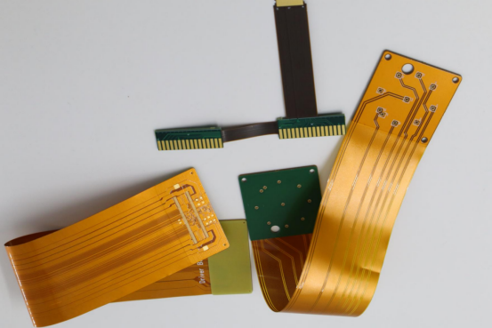
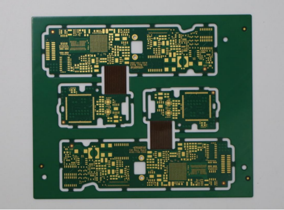
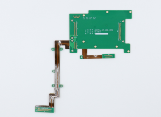
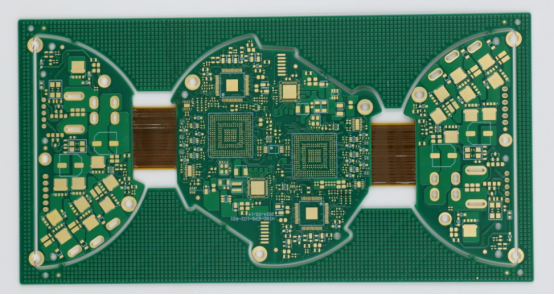
For engineers and designers seeking high-quality PCB solutions to complement their FPC designs, PCBMASTER offers fast, reliable production of rigid-flex boards. With standard rigid-flex boards delivered in as fast as 7 days for 6–20 layers, and support for HDI multi-layer designs using top materials from DuPont, Panasonic, and Shenggao, PCBMASTER ensures your flexible circuits meet the highest standards. Even the smallest soft sections can be as short as 0.8mm, giving designers the freedom to create innovative, space-saving devices.
With PCBMASTER’s capabilities, integrating FPC connectors into advanced electronics has never been easier or faster.
FAQs
1. What is the difference between ZIF and non-ZIF FPC connectors?
ZIF (Zero Insertion Force) connectors allow the flexible circuit to be inserted without applying force. They use a locking mechanism that opens the contacts for easy insertion and then secures the connection when closed. This reduces the risk of bending or damaging the FPC.
Non-ZIF (or LIF – Low Insertion Force) connectors rely on pressure to make contact. The FPC is pressed directly into the connector, which is simpler and more cost-effective but requires careful handling to avoid damaging the cable.
Summary: ZIF connectors are ideal for delicate or repeatedly assembled devices, while non-ZIF connectors are suitable for more permanent, low-cost applications.
2. How do I choose the right pitch size for an FPC connector?
The pitch is the distance between adjacent pins. Common sizes are 0.3mm, 0.5mm, and 1.0mm.
Smaller pitch allows higher pin density and supports compact devices but may increase assembly difficulty and signal interference.
Larger pitch is easier to handle, reduces crosstalk, and is suitable for low-speed connections.
Selection tip: For high-speed or high-density applications, a 0.3–0.5mm pitch is common. For simpler or low-speed circuits, 1.0mm pitch may suffice.
3. Can FPC connectors handle high-speed data transmission?
Yes, FPC connectors can support high-speed signals, but signal integrity depends on design.
Factors such as pitch, contact material, impedance matching, and connector layout affect performance.
Using shielded layouts or proper grounding can minimize crosstalk and EMI, ensuring reliable high-speed transmission.
Example: Modern smartphone displays often use 0.5mm pitch ZIF connectors to carry multiple high-speed data lines without signal degradation.
4. Wat are common causes of FPC connector failures?
Improper insertion: Misalignment or excessive force can prevent full contact.
Damaged contacts: Bent, worn, or corroded pins reduce conductivity.
Debris or contamination: Dust, lint, or solder residues can block electrical paths.
Mechanical stress: Excessive bending, vibration, or repeated mating cycles may loosen or damage the connector.
5. How do environmental factors affect FPC connector performance?
Temperature: Extreme heat or cold can cause material expansion, contraction, or reduced conductivity.
Moisture and humidity: Can corrode contacts and reduce electrical reliability.
Vibration and mechanical stress: In automotive or industrial applications, excessive vibration may loosen connections if the connector isn’t properly secured.
Solution: Choose connectors with temperature-rated materials, protective coatings, and secure mounting features to maintain reliable performance in harsh environments.

