


Expert Through Hole PCB Assembly for Prototypes & Low-Volume Production
When you are making a new electronic product or testing a prototype, you need a way to connect all the parts safely and reliably. This is where through-hole PCB assembly comes in. In this process, the legs of electronic parts go through small holes in the circuit board and are soldered on the other side. This makes a very strong connection that can handle vibration, pulling, and even rough use.
Through-hole assembly is still very important today, even though many modern boards use surface-mount technology (SMT). It is the best choice for prototypes, small batches, and parts like connectors, big capacitors, or switches that need extra strength.
In this article, we will explain step by step how through-hole PCB assembly works, why it is a good choice for prototypes and low-volume production, and how working with an expert service can save you time and improve quality.
What Is Through-Hole PCB Assembly
Through-hole PCB assembly is a process where the legs, or leads, of electronic components are inserted into small holes drilled in the printed circuit board (PCB). Once the leads are through the board, they are soldered on the other side. The solder holds the part in place and allows electricity to flow through the connection. This can be done in two main ways:
l Wave soldering, where the whole board passes over a wave of hot liquid solder that attaches all the parts at once.
l Hand soldering, where a person uses a soldering iron to attach parts one by one.
Because the leads go through the board, the connection is very strong. This makes it a good choice for parts that face mechanical stress, like connectors, switches, or heavy components.
Through-Hole vs. Surface-Mount (SMT)
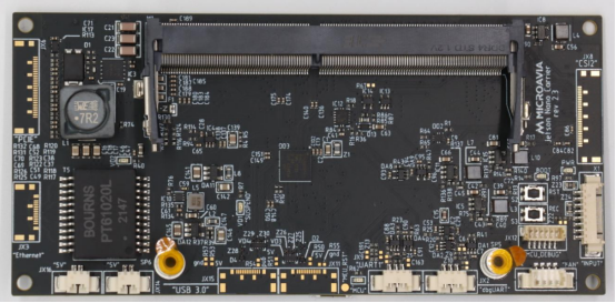
Surface-mount technology (SMT) is a newer method where components are placed directly on the surface of the PCB without passing through holes. SMT is faster and better for mass production because it uses machines to place many small parts very quickly.
However, through-hole technology (THT) is still important. It is easier for hand assembly, better for testing new designs, and offers stronger physical connections. In many boards, both methods are used together — SMT for small parts and THT for big or strong parts.
Common Uses in Prototypes and Low-Volume Production
Through-hole assembly is very popular for prototypes because it allows engineers and hobbyists to easily replace or adjust parts during testing. For low-volume production, it provides a reliable way to build boards without the high cost of setting up full SMT assembly lines. It is also used when making industrial controls, power supplies, and products that must survive tough environments where strong solder joints are critical.
Step-by-Step Process of Through-Hole PCB Assembly
1. Design and File Preparation
Every good assembly starts with good documentation. Before any part is soldered, engineers prepare three important files:
l Gerber files, which are like a map of the PCB showing where copper traces, holes, and pads are located.
l BOM (Bill of Materials), a list of every component needed, including part numbers, values, and quantities.
l Assembly drawings, which show where each part should be placed on the board.
Having clear and correct files avoids mistakes and saves time later. If any of these documents are wrong, the entire assembly can fail or require costly rework.
2. Component Preparation and Insertion
Next, all components are collected and checked against the BOM. Workers or automated machines then place the leads of the components into the matching holes on the PCB. This step requires accuracy so that every part is in the right place and facing the correct direction (important for polarized parts like diodes and capacitors).
In prototypes or very small batches, this is often done by hand. For bigger jobs, automated insertion machines can speed up the process and reduce human error.
3. Soldering Methods
Once the components are in place, they must be soldered. There are three common methods:
l Wave soldering: The PCB passes over a wave of hot molten solder, which solders all the connections at once. This is fast and great for medium- to large-volume production.
l Selective soldering: Used when only certain areas of the board need soldering, often when the board also has SMT parts.
l Hand soldering: Perfect for prototypes, repairs, or very small runs. A skilled technician uses a soldering iron to solder each pin carefully.
Each method is chosen based on the size of the job, type of components, and budget.
4. Inspection and Testing
After soldering, the board must be checked carefully. Visual inspection ensures all components are seated correctly and no solder bridges are causing short circuits. For critical boards, AOI (Automated Optical Inspection) is used to check every solder joint quickly. Functional testing is also done — the board is powered on to make sure it performs its job without errors.
5. Cleaning and Rework
Some flux residue from soldering can stay on the board and attract dirt or moisture. Cleaning removes these residues and helps prevent future corrosion or failures.
If any defects are found, rework is performed — this could mean resoldering a joint, replacing a part, or fixing a broken trace. Only when the board passes all checks is it ready for packaging and delivery.
Key Advantages of Through-Hole Assembly
High Reliability
One of the biggest advantages of through-hole assembly is its strength. Because the leads of components go through the holes in the board and are soldered on the other side, the joint is very strong. This means the parts stay in place even if the board faces vibration, pulling, or rough handling. For example, in a car or an airplane, boards must survive shaking and stress. Through-hole connections are trusted in these situations because they do not break easily.
Easy for Prototypes and Adjustments
Through-hole assembly is also great for making prototypes. When testing a new design, engineers often need to replace a part, change a value, or try different components. With through-hole parts, this is easy to do by hand. You can remove one resistor and put in another, or swap a capacitor without special machines. This makes learning, testing, and improving much faster and less expensive.
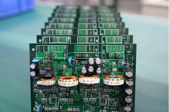
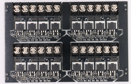
Better for Power Components and Connectors
Some electronic parts, like power transistors, big capacitors, or heavy connectors, need strong support. These parts carry high current or generate heat, and they cannot stay fixed with only small surface pads. Through-hole mounting gives them a solid anchor to the board, helps spread the heat, and ensures the current flows safely. For example, the power supply in a computer often uses through-hole parts because they are stronger and last longer under stress.
Challenges & Solutions in Through-Hole PCB Assembly
High Labor Costs
Through-hole assembly often requires more manual work than surface-mount assembly. Hand-inserting components and soldering each lead takes time and skilled workers. This can make production more expensive for larger volumes.
Solutions:
l Use automation where possible, such as insertion machines for repetitive parts.
l Plan workflow carefully to reduce unnecessary handling.
l Combine skilled manual labor with machines to balance cost and quality.
Lower Production Efficiency Compared to SMT
SMT can place and solder thousands of small components very quickly, making it faster than through-hole assembly. For large-volume production, this difference can slow down delivery.
Solutions:
l Use a mixed assembly approach, placing small components with SMT and large or heavy components with through-hole technology.
l Focus through-hole assembly on prototypes and low-volume runs where speed is less critical.
l Optimize the process flow to reduce downtime between insertion and soldering.
Hole Precision and Soldering Defects
Through-hole assembly requires precise drilling of PCB holes and accurate soldering. If a hole is too small or misaligned, the component may not fit. Poor soldering can lead to cold joints, weak connections, or short circuits.
Solutions:
l Use strict quality control during PCB fabrication to ensure hole sizes and placement are correct.
l Inspect solder joints visually and with automated systems like AOI (Automated Optical Inspection) when possible.
l Provide training for technicians to maintain high-quality hand soldering.
l Rework any defective boards promptly to prevent product failures.
Why Work with Experts in Through-Hole PCB Assembly
Professional Process Control and Quality Assurance
Expert PCB assembly companies have experience, skilled technicians, and controlled processes. They can ensure that every hole is drilled correctly, every component is placed in the right position, and every solder joint is solid. This reduces the chance of mistakes that could cause boards to fail. Professionals also use quality checks like visual inspection, AOI, and functional testing to catch problems early.
Save Time and Reduce Rework Risk
Building PCBs by yourself, especially for prototypes or small batches, can take a long time. Mistakes often mean you have to redo the work, which is costly and frustrating. Working with an expert service saves time because they follow tested procedures, use proper equipment, and handle challenging components efficiently. This means fewer errors and less rework, so your project moves faster from design to finished board.
Support for Rapid Transition from Prototype to Production
Many projects start as a small prototype, then move to low-volume production, and eventually to larger runs. A professional assembly service can support this entire journey. They can quickly adjust the process, scale production, and combine through-hole with surface-mount components as needed. This flexibility makes it much easier to meet deadlines and respond to market demands.
Conclusion
Through-hole PCB assembly remains a powerful and reliable method for building prototypes and small-volume production boards. Its strong mechanical connections, ease of testing and adjustment, and suitability for heavy or high-power components make it a preferred choice for engineers and hobbyists alike.
Choosing a professional through-hole PCB assembly service can make a big difference. Experts ensure high-quality soldering, reduce errors, and save time, helping you get your project from prototype to finished product faster and with fewer problems. This improves reliability and gives your product a better chance of success in the market.
If you want to make your electronics projects easier, safer, and more reliable, consider working with PCBMASTER, a professional PCB manufacturer and assembly service provider. They can support you from prototype design to low-volume production, ensuring your boards are built correctly and efficiently.
FAQs
Can through-hole PCBs handle high temperatures better than surface-mount boards?
Yes, through-hole components usually handle heat better because their leads go through the board and are soldered on both sides. This stronger mechanical connection helps parts stay in place even when the board heats up during use. Power resistors, transformers, and large capacitors often use through-hole mounting for this reason. While SMT components are smaller and convenient, they may detach or fail more easily under high heat or stress.
How can I remove a through-hole component safely without damaging the PCB?
To remove a through-hole part, first heat the solder joint on the back of the board using a soldering iron or a soldering station. Use a desoldering pump or solder wick to remove the melted solder. Gently pull the component out once the solder is free. Always heat each pin carefully and do not force the component, otherwise you might lift pads or damage traces. Working slowly and methodically keeps the board intact.
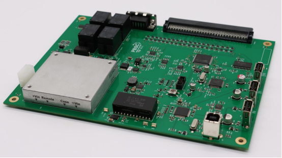
Is it possible to mix through-hole and surface-mount components on the same PCB?
Yes, this is called mixed-technology assembly. Many modern PCBs use both SMT and through-hole parts. SMT handles small, lightweight parts quickly and efficiently, while through-hole is used for heavier or high-power components. Mixed assembly allows designers to balance speed, cost, and reliability. Boards are first assembled with SMT, then through-hole components are added using wave soldering or hand soldering.
How can I identify the correct orientation for polarized through-hole components?
Polarized components, like electrolytic capacitors, diodes, and LEDs, have a specific direction they must be installed. Look for marks on the component (like a stripe for a diode or a long lead for the positive side of a capacitor). The PCB often shows a symbol indicating which way it should go. Installing them the wrong way can prevent the circuit from working or even damage the part. Always double-check markings before soldering.
Why are through-hole PCBs still used in educational kits and DIY projects?
Through-hole PCBs are easier for beginners to work with. The leads are larger and easier to see, and parts can be soldered by hand without special machines. This makes them perfect for learning electronics, experimenting, and building small projects at home. Students and hobbyists can practice soldering, troubleshooting, and replacing components safely, which helps them understand how circuits work.

