


PCB: Improving Quality through Accurate Testing
The key role of PCB testing in modern electronic products
This is something most people don't think about: the smartphone in your pocket, the medical device that monitors your heartbeat, the braking system in your car, all rely on a perfectly functioning printed circuit board. And I said perfect. One tiny product flaw can turn a perfectly designed PCB into a potential disaster.
I've worked in this industry long enough to see what happens when testing is ignored. Recalls, lawsuits, brands that took decades to build were destroyed in a matter of months. The stakes have never been higher, especially now that we're cramming more components into smaller boards than ever before. Data shows, the printed circuit board market size stood at USD 81.01 billion in 2025 and is projected to reach USD 104.58 billion by 2030, translating into a 5.24% CAGR. A trend driven by factors ranging from 5G networks to electric cars. With this growth, the demand for quality has also become higher and higher.
What keeps me up at night is not just finding defects, but making sure we catch them before they get to the customer. It is at this point that proper testing becomes non-negotiable.
The Challenge: Why choosing the right firmware for testing is critical for “Optimal performance.”
Let Me Be Frank: Your Test harness may make or break your entire quality strategy. I've seen manufacturers waste tens of thousands of dollars on the wrong device, only to deal with false failures that slow production or, worse, defects that get the product to the site.
Test fixtures are the unsung heroes of electronics manufacturing. They're the interface between your carefully assembled PCB and the expensive testing equipment you've invested in. If you make the wrong choice, you'll pay far more than the original purchase price. We're talking about wasted engineering time debugging virtual failures, scrap boards that are actually intact, and real defects that result when your fixtures fail to reach critical test points.
The correct mounting device? It will pay off faster than you think. Higher output, fewer field failures, and test cycles that are actually synchronized with the production line won't be the bottleneck that kills your output.
What you'll learn: a strategic framework for smart firmware selection
This won't be another boring technical manual. I'll share my experience over the years helping manufacturers make these decisions, including good, bad, and costly mistakes.
You'll get a practical framework to think about your situation and understand what different types of fixtures actually offer (compared to what the salesperson claims) , and avoid the common pitfalls encountered by even experienced engineers. By the time you're done, you'll know exactly what questions to ask, what tradeoffs are critical to your production environment, and how to justify the investment to those who control the budget.
Whether you're setting up your first test line or finally replacing a fixture that's been causing problems for years, this guide will help you make a decision that makes you feel confident.
Understanding PCB test fixtures: the basis for quality assurance
What is PCB test fixture? (definitions, including test fixtures, test heads, nail beds)
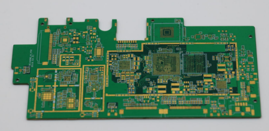
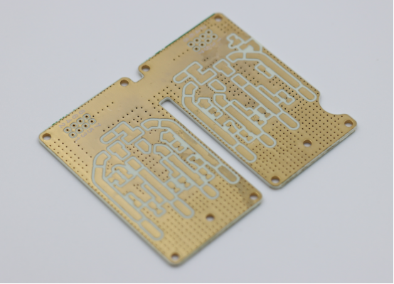
Think of the test fixture as a custom handshake between the PCB and the test equipment. At its simplest, it is a precision-machined frame that holds the circuit board in place, at the same time, a series of spring-loaded pins (called Pogo pins) make temporary electrical contact with specific points on the circuit.
The nickname “Bed of nails” comes from its appearance: hundreds or even thousands of nails protrude from the base of the fastener, each nail placed with astonishing precision, to hit specific test pads, channels, or assembly wires on the board. Even a few thousandths of an inch can cause intermittent contact, which can lead to all kinds of headaches.
Modern fixtures have become rather complicated. We're talking about a vacuum system that pulls the plates down for stable contact, a pneumatic actuator that precisely controls the force exerted by the pins, and a Modular design system that, when the plate layout changes, it allows you to replace parts. The best fixtures even have built-in shielding to prevent electrical noise from interfering with sensitive measurements.
But the point is that complexity is only important if the basic design meets your actual testing requirements. I've seen some well-designed fixtures, but it's all wrong for the application.
Why PCB test fixtures are essential (to ensure product reliability, identify defects, prevent failures)
You know what's cheaper than dealing with on-site failures? Find the fault before it happens. The ratio is about 100 to 1, and probably higher if you're in the medical or automotive industry, where recalls can run into the millions.
The test fixture allows you to systematically examine every key aspect of the assembly panel. Short Circuit between tracks? Got It. Reverse mounting of components? Got It. The welded joint looks good, but the resistance is high? Got It. Capacitor missing? You get the idea.
But the real value isn't just in finding bad boards. Good test data can tell you why your board is malfunctioning and what aspects of your assembly process need attention. Perhaps you see short boards clustered around a connector, which could be a mold problem or a reflow configuration problem. Fix the root cause, and your productivity will go up and defects will go down.
In regulated industries, this is not optional. Attempts to send medical devices without recording test results proving that each unit is working properly. The FDA will say something to you that you may not like.
Test fixture core components (Pogo pin, test probe, test pin, test point, test rack, carrier test board)
Let's talk about the actual content of these things. The main character in the show is the Pogo Pina spring-loaded probe, which is basically a miniature mechanical marvel. In this small package, you have a piston, a barrel, and a precisely calibrated spring that maintains contact during thousands of compression cycles. Quality is of the essence here. Very important.
Then there is the receiver board, sometimes called the interface board or the converter board. This is a custom PCB that sends the signal from each pogo pin to the connector that plugs into the test device. Designing this board is not an easy task. You need to consider Signal integrity, proper grounding and ensure that high-speed signals do not generate noise or degrade.
The fixture frame holds all the parts together. Processed aluminum is usually used because it is light, strong, and does not rust. Here, precision is crucial. Loose tolerances mean the plates don't stay in the same position, and you'll Chase Phantom faults that are really just alignment problems.
You also need some way to secure the circuit board. Vacuums are popular because they are fast and don't require mechanical clamping, which can put pressure on the PCB. Some designs use locating pins that can be inserted into PCB tool holes. No matter what method you choose, repeatability is important. Load the circuit board ten times and each time you should get the same probe contact.
Define “Best performance” in PCB testing (accuracy, repeatability, test speed, fault coverage, cost effectiveness, yield improvement)
When I talk about “Optimal Performance”, I'm not talking about some theoretical ideal, but about real-world metrics that affect your bottom line.
Accuracy means that the fixture does not introduce errors. If the resistance measurement is 100 ohms, the fixture should not increase the contact resistance by 5 ohms, which will cause the measurement to fail. For high-speed digital signals, the fixture should not distort the waveform or add so much capacitance that timing measurements become meaningless.
Repeatability is also crucial. Test the same board five times and you should get essentially the same results. If you see a change, it could be a problem, it could be probe wear, it could be a problem locating the board, or it could be electrical noise. Whatever the reason, it will destroy your confidence in your test data.
Test speed is when rubber meets the road in mass manufacturing. When you run 500 boards per day, you've just achieved meaningful productivity by eliminating 10 seconds from your test cycle. But speed can not achieve cycle time goals at the expense of coverage flaws, a false economy that can seriously affect you.
Defect coverage is probably the single most important indicator. How many possible defects can you actually detect? World-class testing strategy at 95% or higher. Anything below 85% , you're basically risking quality.
Yes, all of this must make financial sense. A fixture that provides 98% coverage but costs twice as much as 95% coverage may or may not be worth it, depending on your failure cost and throughput. This is the way you need to weigh and analyze the actual data, rather than go with your gut.
Strategic considerations prior to selection: laying the foundation for success
PCB design features and specifications
Your PCB design even determines the possibilities for test fixtures. I learned this the hard way early in my career when I assigned a fixture to a board whose components were so tightly packed that there was barely room for a probe. It is a costly lesson.
Start by really understanding the physics of your circuit board. How Big Is It? How Thick? Is the layout one-sided or two-sided? What is the minimum distance between components? Where are the test points, and can you even access them with standard probes?
Here's a reality check: if your board designer doesn't consider testability, you'll pay a price in fixture complexity and cost. Ideally, pcbs should have special test-point pads placed for probe access, rather than just expecting you to hit a component lead between two other components. Every good design for testability (DFT) board I've used has been cheaper and easier to test. Every piece of it.
Electrical characteristics are also important. Testing circuit boards with high voltage cross sections requires special insulation and safety interlocks. Stronger Pogo pins for high-current power supplies. The RF circuit requires the fixture's own impedance to control the signal path. If these requirements are ignored during the planning process, you will either get a fixture that doesn't actually do the job, or you will get an expensive replacement order in the middle of the project.
Test requirements and objectives
Before you choose the right fixture, you need to know exactly what you're testing. This may sound obvious, but you'd be surprised how often this step is overlooked.
Are you primarily looking for short circuits, openings, faulty parts, and tombstones? This is the world of manufacturing testing, where in-circuit testing is excellent. Or do you need to verify that the circuit is actually running under power? This is a different area and requires a different approach.
List the defects that must be detected and the defects that are easy to detect. If a particular failure mode poses a security risk, it must be detected. You'll design your entire testing strategy around making sure that these defects never escape. Capturing a less serious problem can be an acceptable trade-off if it doubles the cost of your fixture.
Compliance requirements also need to be considered. Manufacturers of medical devices need different validation from consumer electronics. The auto industry has its own standards. Aerospace and defense? A completely different level. Knowing these requirements in advance can prevent you from finding yourself lacking key documentation or competencies in the fixture design process.
Production capacity and product life cycle
This is where the business case becomes real. How many of these would you actually make?
If you plan to produce 100,000 units a year for the next five years, invest in the best plant you can afford. The cost per test board will be low, and optimization can pay big dividends in mass production. An extra $50,000 to shave 15 seconds off the test time? In high-volume production, this could pay for itself in a year by adding capacity.
On the other hand, if you're making a total of 500 panels for a short-life product, $100,000 for custom fixtures is financially insane. You want something cheaper, simpler, maybe even a flight detection system that doesn't require any custom tools.
The tricky parts are medium-sized base medium capacities, uncertain lifecycles, and products that may or may not grow significantly. This is where modular fixture design and flexible approaches continue to work. You want a product that can scale up successfully, but if you keep the capacity modest, it won't go bankrupt.
Also, please be honest and tell us how often your circuit board design changes. If you ECO every other month, a highly optimized custom fixture will take half its life to modify. Even if a single test cycle is slower, a more flexible approach may make more sense.
Budget and return on investment
Let's talk about money. Test fixtures aren't cheap, and if you've never bought one before, the sticker impact is real.
Simple clamps for simple sheets may cost between $10,000 and $25,000. Moderately complex designs typically cost between $30,000 and $75,000. Complex fixtures with extensive automation, high needle count, and complex functions can easily reach $150,000 or more. I've seen fixtures for extremely complex aerospace components sell for more than $300,000.
But what matters is the total cost of ownership, not just the purchase price. That cheap fastener that requires constant maintenance and has contact reliability problems that cause it to fail? In the long run, it will cost more than a good fastener that just works.
Calculate the real rate of return on investment (Roi) . How much do on-site failures cost you in warranty work, transportation, customer dissatisfaction, and brand damage? If the total impact cost of an escape defect is $10,000, and a better fastener prevents only 10 escapes during its lifetime, you get paid.
And don't forget operating costs. Test time translates directly into labor costs and equipment utilization. Maintenance requirements, the schedule for replacing pins, and how easy it is to troubleshoot all affect lifetime economics. Sometimes, a good fixture actually has a lower total cost of ownership because it's more reliable and requires fewer nannies.
Integration with the overall test strategy and environment
Your fixtures do not exist in isolation as part of the broader testing and quality ecosystem.
What test equipment do you have? Fixtures need to be physically and electrically paired with your test equipment, so compatibility is not optional. If you are running Keysight ICT devices, your fixtures need to meet their interface specifications. Teradyne? Different interfaces. These things are not standardized across vendors.
Think about how fixture testing fits into the overall quality process. Perhaps you first perform an Automatic Optical Examination (Aoi) to find obvious assembly problems, then an ICT for electrical verification, and finally a functional test for operational verification. Each step has different goals and discovers different types of defects. Optimizing the entire process is more important than optimizing any single step.
Practical matters matter, too. How much floor space do you have? Where will the fixtures be installed? Does the location have the correct utility function (Compressed air, vacuum, internet connection) ? Who will be in charge of operating it and what is their skill level? Does the test data need to be integrated with your MES or quality management system?
I've seen some beautiful fixtures fail in production because no one considered the fact that operators needed to lift heavy boards over their heads to load them, either the test site is next to a giant motor that produces electrical noise, or the facility does not have enough Compressed air capacity to operate pneumatic actuators.
Type and performance impact of PCB test firmware
IC test (ICT) firmware
In-circuit test fixture is the main force of electronic manufacturing industry. If you've worked in this industry for more than a week, you've probably seen a sophisticated ICT system.
The concept is elegant: probe each component in the circuit and verify its electrical characteristics. Measure the resistance to determine the correct value. Check capacitors for capacitance and leakage. Diode and transistor connector for verification. Digital integrated circuits for short circuit and basic functional testing. All of this is done in parallel, usually in 30 to 60 seconds for a full board test.
The power of ICT lies in its combination of comprehensive coverage and fast execution. A well-designed ICT fixture can detect 90-95% of manufacturing defects. It detects short circuits, openings, incorrect part values, reverse polarity, missing parts, and most weld joint defects. Diagnosis is also usually good-when a component fails, the system tells you exactly which part is faulty and what went wrong.
What are the disadvantages? You need to actually touch the test point. As the components on a circuit board get smaller, it becomes harder and harder to find a place to put the probes. The ball grid array (BGA) component is particularly challenging because all the wiring is hidden below. If the designer has the foresight to include them, you'll end up relying on channels or test pads.
ICT also has limitations when it comes to functional testing. Sure, it can verify that the component exists and has the correct value, but it can't really tell you whether the circuit is working as designed . ICT can not capture complex timing issues, system-level interactions, firmware issues, and so on.
But for pure product defect detection, ICT is king. This is why it remains the most widely deployed test method in the industry.
Functional test (FCT) firmware
Functional testing takes a completely different approach: powering the board and verifying that it does what it's supposed to do.
FCT fixtures look different from ICT fixtures. Instead of hundreds of probes accessing test points throughout the board, there are usually connectors connected to the board's normal I/O interfaces, which are identical to those used in the final product. You apply power, send an input signal, and measure the output response. Does it start? Can it communicate through a serial port? Do leds light up when they should? Is the specification output voltage under load?
The beauty of functional testing is that it verifies the actual operation of the circuit. You're not just checking that the component values are correct, you're proving that the circuit is working. This covers an entire category of defects that ICT overlooks: timing issues, firmware issues, complex component interactions, and performance degradation.
The challenge with FCT is that it is generally slower and requires more complex test development. You need to really understand how the circuit should behave and create test sequences that fully perform that behavior. When a failure occurs, diagnosis can be tricky, and functional symptoms do not always point directly to the root cause.
FCT fixtures range from simple basic power and multimeter setups to complex systems including programmable loads, signal generator, oscilloscopes and environmental chambers. My FCT fixtures include custom load libraries, RF signal generator, and even mechanical actuators for pressing buttons and verifying indicators.
For complex analog circuits, rfics, power supplies, and products with significant firmware content, functional testing is essential. Without functional testing, you can't have confidence in manufacturing quality.
Combined/mixed test fixture
Why choose between ICT and FCT when you can use both?
Hybrid fixtures combine in-circuit testing for full component-level verification with functional testing for operational verification. You get the best of Both Worlds: fast, comprehensive defect detection from ICT, and confidence that the circuit is actually working through FCT.
These systems typically run ICT first to detect manufacturing defects and then switch to functional mode as the sheet passes through. That makes sense -- why waste time performing functional tests on a board with a short circuit or missing parts? Use ICT to quickly find obvious defects, and then use functional testing to verify the correct action.
Fixture design becomes more complex because you need both the nail bed probe array and the functional interface connections. Many hybrid systems use intelligent switched networks to reconfigure signal paths between test modes. This allows you to use the same fixture for both tests without having to manually move the sheet between different fixtures.
The business case for hybrid fixtures depends on whether you really need both types of testing and whether integration is cheaper than separate fixtures. For high reliability applications, such as medical devices, automotive electronics, aerospace, etc. , universal coverage usually justifies the investment. For simpler products or smaller volumes, the added complexity and cost may not make sense.
I generally recommend a hybrid testing approach for products where failure on site can be catastrophic or extremely expensive. Hybrid testing provides the highest level of confidence that can be achieved when you absolutely need to make sure that every board runs perfectly.
Special test fixture for special requirements
Sometimes a standard approach simply doesn't cut it, and you need to tailor some engineered product for a particular situation.
The flight detection fixture is a completely different animal, with no nail beds. Instead, a movable probe slides under computer control, touching the test point in turn. What are the big advantages? No customization tools are required. You can write probe paths in software, and the same fixture can test completely different boards by loading a new program.
This flexibility makes the flying probe ideal for prototyping, low-volume production, and frequently changing products. However, sequential probes are much slower than parallel ICT test times, perhaps 5-10 minutes instead of 30-60 seconds. In high-volume cases, this is a deciding factor. At low volumes, the savings in fixture costs and deployment time far outweigh the compensation for slow testing.
Boundary scan tests use special test circuits built into digital integrated circuits (IEEE 1149.1 JTAG standard) . A simple fixture with just a few probe points can access the entire component chain through a boundary-scan interface. This works well on high-density digital circuit boards, where physical probe access is nearly impossible. The problem is that it only applies to components that support boundary scans, so it is often used in conjunction with other testing methods.
For special applications, fixtures become very special. High-power testing may require liquid cooling and handling of hundreds of amperes of heavy contactors. RF testing requires accurate coaxial connections and shielding enclosures. Environmental testing integrates hot cell and humidity control. Battery testing involves complex charging/discharging systems and safety interlocks.
The key to using dedicated fasteners is to find a manufacturer who has done similar projects before. These are not off-the-shelf solutions -- they require your true engineering expertise and experience in a particular field.
Key design and engineering aspects of optimal fixture performance
Pogo pin selection and configuration
Let me tell you about Pogo pins, because this is where many fasteners fail (literally) .
These spring-loaded probes look simple, but there's serious engineering involved in this little package. You have a piston in contact with the PCB, a tube to guide the piston, and a spring to provide the contact force. There is a big difference in quality between cheap and good needles, and believe me, you can feel the difference in the manufacturing process.
The geometry of the tip is more important than zero realizes. Round tips are the most common— they're looser in alignment and gentler on PCB gaskets. The tips are aggressive and can actually penetrate oxides or contaminants for contact. They are great for test gaskets that aren't completely clean, but they can damage the gaskets over time. The flat tip distributes forces over a larger area and is suitable for precision surfaces or components that can not withstand point loads.
The Spring Force is a balancing act. Too light can lead to intermittent contact, especially when pins are worn. Too heavy will damage the PCB gasket, bending marks, and even lead to plate cracking. Most applications require a force of 50-100 g per pin, but this depends on the gasket finish, the plate, and the number of tests per plate.
The current level must not be an afterthought. Standard pins can handle 1-3 amps. Do you need to test the power or battery management system? You will need to set the heavy pin to a current level of 5,10, or even 20 amps. Use small pins to handle high currents, and you'll really burn out. I've seen pins get so hot that they melt the mounting plates.
Needle life expectancy ranges from 50,000 cycles for basic needles to over 1 million cycles for advanced designs. Calculate your output, and you'll know how often you need to change needles. Budget pins may save money up front, but if you replace them monthly instead of once a year, they'll be replaced automatically and quickly.
Fixed materials and construction
The physical structure of the fixture determines whether it will stand the test of time in production or become a maintenance nightmare.
Most fixture bottom plates use G10 or FR4 epoxy fiberglass materials. It is dimensionally stable, machine clean, and provides good electrical insulation. The key factor is the accuracy of the hole position. As you drill hundreds or thousands of pin holes, each pin hole needs to be within a few thousandths of an inch of the target location. This requires precision numerical control equipment and skilled processing technology.
The fixture frame is usually made of machined aluminum. Lightweight makes operation easier, rusts less, and can be machined perfectly to achieve precise tolerances. For very large fixtures or fixtures that require maximum stiffness, steel may be necessary, but you will pay the price in weight.
The quality of construction distinguishes fixtures that have been in use for many years from those that cause persistent headaches. Look for accurate assembly and finishes, proper surface finishes to prevent corrosion, sturdy mounting hardware that won't loosen from vibration, and Modular design that allow you to replace worn parts without rebuilding the entire fixture.
Alignment features include guide pins, tool holes, and vacuum tubes, all of which need to be rock-solid. If the board moves a bit during the test, you'll have intermittent probe contacts and random failures, which can be fatal for debugging.
I always tell people: you can't check the quality of a fixture after the fact. Either it gets it right the first time, or you have to live with it forever. Pay the cost of quality construction in advance. You'll thank yourself later.
Signal integrity and noise reduction
This is where things get tricky but extremely important, especially for high-speed digital or precise analog measurements.
Each pogo pin is an antenna that receives electrical noise. Each mark on the receiving plate has a parasitic capacitance and inductance. Every inch of cable between the fixture and the test equipment reduces the Signal integrity. For low frequency DC measurements, you can probably ignore these things. For faster or more accurate measurements, you'd better pay more attention.
Probe length is enemy number one in Signal integrity. The shorter the better. This means a carefully designed receiver board that minimizes the distance from each pin to the point where transmission is required. For high-speed signals, controllable impedance transmission becomes essential. You need to calculate the track width, dielectric thickness, and ground plane spacing to maintain a characteristic impedance of 50 or 75 ohms.
Grounding strategies can improve or reduce noise performance. A continuous ground plane on the receiver board provides a low impedance return path. The ground pin around the sensitive signal pin acts as a shield against crosstalk. But the tricky part is that part of the ground loop may actually introduce noise rather than eliminate it. You need to know the current return path and avoid creating loops to catch magnetic interference.
For truly sensitive measurements, millivolt analog signals or accurate resistance measurements may be considered. Kelvin, Connect is your friend. Separate the current path from the voltage sensing path so that the voltage drop in the wire does not affect your measurement.
RF testing takes Signal integrity to a new level. You need coaxial connections, properly terminated transmission lines, and usually electromagnetic shielding around the fasteners. Terminal length is very important. The quality of connector is very important. Everything is important. One Bad Connection and your 2 GHz Signal integrity is meaningless.
Integration with test equipment and software
The quality of a fixture depends on how well it is integrated with the test system that drives it.
Physical integration begins with mechanical installation. Most test equipment has standardized mounting interfaces, but size and hardware requirements need to be validated before finalizing fixture design. Fixtures need to be reliably matched against tester misalignments, which can result in intermittent connections and phantom failures.
Electrical interface connectors are typically customized for each equipment manufacturer. Be absolutely sure to use the correct connector type, pin, and electrical specifications. If something goes wrong, it means your fancy fixture can't even communicate with the testers.
The safety interlock prevents the tester from applying high voltage or current when the fixture is opened. This may be a pneumatic sensor detecting clamp closure, a limit switch or an electronic interlock circuit. This is not an optional life-safety device to protect the operator from electric shocks. Please design properly and test thoroughly.
Software integration determines your efficiency in developing and deploying tests. Fixed files describing probe locations, pin assignments, and electrical characteristics need to be in whatever format the test software expects. In the case of ICT systems, this is usually the exclusive domain of each manufacturer. For functional testing, you may want to use a more open platform such as Python or LabVIEW.
Advanced features such as the e-fixture ID (the RFID tag or memory chip in the fixture) prevent operator error by automatically configuring the tester when the fixture is installed. Diagnostic function self-test function to verify fixture electrical integrity capture issues before they lead to production leaks.
The best fixtures feel like a natural extension of the test equipment. Load a board, press the start button, and everything will work. This seamless integration does not happen by accident, but is the result of careful design and thorough verification.
The Strategic Choice Process: A step-by-step guide
Step 1: clearly define test objectives and performance metrics
You Can't choose the right fixture until you know exactly what “Right” means in your situation.
Sit down with engineering, manufacturing, and quality stakeholders. Identify which defects must be found. Manufacturing defects, such as shorts and openings? It could be. Component Value Error? It could be. Functional timing issues? Maybe, depending on the complexity of your product. Create a priority list.
Set quantitative goals. What percentage of fault coverage do you need? The industry average is about 85-90% , but medical devices and automobiles typically require 95% or more trouble coverage. What is your tolerance for false positives? Each false positive wastes time and money, but reducing false positives to zero can be impractical or costly.
Define the acceptable test cycle time in terms of your beat time (production rate) . If you're making a plate every two minutes, your test should be done in two minutes or it will become a bottleneck. But don't sacrifice coverage for speed. It's a false economy.
Budget constraints are real, but they need to be framed properly. Don't just ask, “What can we afford?” Ask, “What is the ROI for different levels of investment?” A more expensive infrastructure, if it can provide better coverage or faster testing, may have a better return than a cheaper option.
Record all of this. You will refer to these requirements throughout the selection process, and they form the basis for an objective evaluation of the different options.
Step 2: thoroughly analyze the PCB and production environment
Be familiar with your circuit board design. I mean really study it.
Create a comprehensive test point diagram. Where can the probe be physically connected to the circuit? Are there areas of dense component layout where the probe can not be inserted? Are there parts on both sides of the plate? Are there any large parts that are likely to interfere with fixture closure?
If access to test points is restricted, talk to your board designer * now * . Adding test points to the next revision may take you a few days to lay out, but it can save tens of thousands of dollars in fixture complexity. Design-for-test (DFT) is not optional, it is essential.
Evaluate your output realistically. Don't think in numbers. What are the actual forecasts and how confident are you? Is it a mature product for which demand is stable, or a new product for which volumes are uncertain? This uncertainty affects how much you should invest in optimization.
Understand the production environment. Temperature and humidity levels can affect fixture performance. Vibration of nearby equipment may cause contact problems. Floor space may limit fixture size. The skill level of the operator determines how much automation you need and how much you can do manually.
Take a look at your existing test facility infrastructure. What equipment do you already have? What's its status? Is your ICT tester up-to-date and well-maintained, or is it a 15-year-old system held together by Hope and spare parts? It may not make sense to invest in expensive custom fixtures for out-of-date test equipment.
Step 3: assess and prioritize fixture types based on requirements
Now, use real data, not marketing claims, to match fixture types to your needs.
ICT scores well for product defect detection, speed, and diagnostic resolution. But it requires access to test points and doesn't catch functional issues. If your defect profile is dominated by assembly problem phrases, then open, faulty part icts may be your primary solution.
Functional testing is good at verifying circuit execution and capturing system-level issues, but it is typically slow and requires more complex test development. FCT is required if your product has complex analog behavior, programmable firmware, or critical functional specifications that can not be verified through component testing.
Hybrid systems maximize coverage but cost more. Run the numbers. If the incremental cost of a hybrid system relative to stand-alone ICT and FCT is relatively small, and you need both types of testing, then a hybrid system may provide better ROI through integration efficiency.
Specialized solutions such as flight detectors are appropriate for specific scenarios: low volume, frequent design changes, and prototyping. Don't force them into high-volume production because they can be a bottleneck.
Create a decision matrix and rate each option based on your weighting criteria. Be honest about the trade-offs. No perfect solution is the best compromise for your particular situation.
Step 4: choose between custom and standard stationary solutions
This decision often boils down to econometrics and the importance of optimization.
Custom fixtures provide the best performance: perfect probe placement for optimal coverage, minimizing test cycle time, and integration tailored to your device and workflow. You are paying for engineering time for something designed specifically for your circuit board.
The Math is simple: take the incremental cost of custom and standard panels and divide it by the annual production to get the incremental cost per panel. If you make 50,000 panels a year and a custom panel costs $40,000 more than a standard panel, each panel costs 80 cents. Can you prove it by improving coverage, speeding up testing, or reducing failures? Usually.
Standard or modular fixtures have lower up-front costs and faster deployment, but there are trade-offs in optimization. Universal grid fixtures with programmable pin locations provide flexibility at the expense of test time and coverage. The flight detection system completely eliminates the need for custom tools, but runs much more slowly.
For example, standard methods or flight probes are generally preferred at low yields, where the total number of boards is less than 5000. The investment in custom fixtures can not be depreciated in small lots.
Medium capacity is a judgment call. The semi-custom solution uses standard frameworks and components, but has a custom probe layout that balances the differences. You can get zero per cent of the performance benefits of customization without having to pay the full cost of customization.
Another factor: How Stable is your design? If you're doing Ecos on a monthly basis, custom fixtures can take a lot of time to modify. Even if individual tests run slowly, a more flexible approach can avoid trouble.
Step 5: work with an experienced firmware manufacturer/supplier
Selecting the right fastener partner is as important as selecting the right fastener type.
Look for manufacturers with specific experience in your industry and product type. Fixture design for high-speed digital circuit boards requires expertise different from analog, RF, or power electronics. Ask for references from clients doing similar jobs and actually call them. Know what is going well and what is not.
Assessing technological capabilities outside the manufacturing sector. Do they have a design engineer who can optimize your fixture to improve performance? Do they use simulation tools to verify Signal integrity before building hardware? Do they support prototyping and iteration?
The quality system is important. ARE THEY ISO certified? Do they document the process of design review, manufacturing control, and final validation? What is their repair and warranty policy? You need a partner to support their work.
Communication style can tell you a lot. Will they ask probing questions to understand your application, or will they just quote what you specify without rebutting it? The best manufacturers challenge assumptions and offer insights based on their own experience. They should find potential problems before the hardware is made, not after.
Cost should not be the only decision-making factor. The cheapest quotes are often accompanied by hidden costs, poor reliability of connections, difficult maintenance, and inadequate support. A high-end manufacturer offers fixtures that run perfectly for five years, and its total cost of ownership is usually less than a budget option that requires constant attention.
Clear definition of intellectual property rights. Who has the fixture design documents? Can you get a copy of Your Records? If you later need to modify or want a second source, it's valuable to have design data.
Step 6: integration, validation, and deployment plan
Don't assume that a finished fixture will go straight into production and run flawlessly. You need a validation and deployment plan.
Let's start with mechanical verification. Is the plate correct and suitable? Is the clamping system working properly? Is there any clearance problem in the high parts? These may seem basic, but I've seen fixtures that actually can't be closed because no one is responsible for the radiator.
Next up is the electrical verification. Check the probe contact quality throughout the PIN array for consistent, low contact resistance. Make sure there is no short circuit between the pins. For ICT fixtures, many testers have built-in diagnostics that systematically test fixture integrity.
Functional verification uses plates of known good and known defects (if they do not exist, you need to create them) . Verify that the fixture is reliably passing through good plates and capturing defects. This is where you adjust the test limits and verify that the fault coverage meets the requirements.
Conduct correlation research and compare fixture test results with other quality data sources. If you are replacing an existing test method, the results should relate to significant differences that need to be investigated. Compare fixture data with on-site failure information to verify that you have captured the correct defect.
Operator training is often underestimated. Even experienced test operators need to be trained on the new fixtures. Document loaders, security requirements, basic troubleshooting, and routine maintenance. Using photos and videos doesn't rely solely on text descriptions.
Consider a phased roll-out. It might be possible to run the new firmware in parallel with the existing method for a week or two to build confidence before making a full transition. This gives the operator time to adjust and allows you to spot any problems before committing.
Ensuring long-term optimal performance: maintenance and future validation
Routine maintenance for continuous accuracy and reliability
Test fixtures, like bearings, require regular maintenance to maintain good performance.
Wear and tear on Pogo pins is the biggest wear and tear. Pin will not exist forever. Each test cycle compresses the spring and creates friction between the plunger and the cylinder. Eventually, the spring will weaken, the plunger will wear out, and the contact resistance will increase. According to the cycle count and actual performance monitoring, make the replacement plan of pin.
Most manufacturers evaluate pins in 50,000 to 500,000 cycles depending on quality and operating conditions. Keep track of the number of tests you have run and proactively plan for replacement. Failure of waiting pins can cause production interruptions. It is best to schedule replacements during planned downtime.
Regular cleaning prevents the accumulation of contaminants. Solder flow, oxidation and dust build-up at pin tips reduce contact. Clean the pins regularly with isopropyl alcohol and a soft brush. For stubborn pollution, ultrasonic cleaning effect is good. Just don't use abrasives that accelerate wear.
Electrical verification should be part of routine maintenance. Run the fixture diagnostic procedure, check the pin shorts and verify the contact resistance. Many ICT systems automatically use this feature on a monthly basis or whenever you suspect a problem.
Mechanical parts also need attention. A leak may occur in the vacuum system. Pneumatic actuators require lubrication. The alignment pins are worn by repeated loading. These problems are detected early through scheduled inspections before they cause intermittent failures that are difficult to debug.
Maintain a maintenance log. Keep track of what was done, when, and by whom. If you change pins in a certain area more frequently, be aware of any trends that may be due to excessive contact forces or plate alignment issues. The figures drive continuous improvement.
Troubleshoot common fixing problems
In spite of the best efforts, the fixtures still have problems. Knowing how to troubleshoot effectively can minimize downtime.
Intermittent failures are the worst. They drive everyone crazy. The board passes one test, fails the next, and then passes again. The first step is to isolate which test points are unstable. It's usually just a few bad pins, not a systemic problem. Check these pins for damage or contamination. Check for proper compression, but the amount is too small to make reliable contact.
Check the position of the board. Is the Alignment system working properly? If the board moves slightly between tests, the probe contacts become inconsistent. Look for worn guide pins, weak vacuum or loose clamping mechanisms.
High contact resistance is a sign of measurement error or failure in precision testing. Measurement of actual contact resistance using Kelvin's technique. Clean or replace pins that indicate high resistance. Sometimes the problem isn't the pins, but the oxidation of the PCB gasket itself, which needs to address the board's storage conditions.
Error failure good board failure testing is a waste of time and money. Associate a fault with a specific measurement. Are they random or consistent? Random failures indicate intermittent contact. Consistent failures may mean that the test limits are too strict for the actual fastener measurement capability. Sometimes you need to open the limit slightly to take into account changes caused by the fasteners.
Mechanical problems are often obvious: fixtures don't close properly, plates don't stay fixed, and actuators don't move smoothly. These require physical inspection and maintenance. Keep a list of spare parts for common failure mode pins, springs, actuator seals, and alignment hardware.
When troubleshooting is difficult, do not hesitate to contact your fastener manufacturer. Good fastener manufacturers provide technical support and have encountered similar problems before. They can save you hours or days of debugging.
Adaptability and extensibility to meet changing requirements
Smart fixture design anticipates change, rather than assuming that everything stays the same.
If space permits, it can be built at unused probe locations. When Ecos add test points, blank areas in the fixture make modifications easier. Similarly, a receiving board with additional routing capacity is designed. Adding a few tracks is easier than redesigning the entire board.
A modular build is very helpful. If the detector array is a separate module, rather than a large component, you can replace only those parts that are affected by the design change. This reduces modification costs and turnaround time.
Think about product lines. Maybe you have three circuit board variants that share 70% in common. A single fastener with unique interchangeable parts meets the requirements of all three products at a lower total cost than three completely independent fasteners.
Planning for capacity expansion. If the production scale is increased, can you make a second identical fixture to double the capacity? Having a design file and documentation makes replication easy. Or could the fixture be more automated and, at a reasonable scale, add robotic plate handling?
Maintain complete documentation: CAD files, probe layouts, Bill of materials, test procedures, maintenance history. Store it in a safe place and back it up. You will need this data to modify, troubleshoot, or create additional fixtures. I've seen companies lose fixture documentation and end up reverse-engineering their own fixtures years later. Don't be that company.
Use test data for continuous improvement
Your test fixtures are producing valuable data every day. Take advantage of it.
Capture detailed test results, not only pass/fail, but also actual measurements for each parameter. Modern data collection is cheap and simple. Store everything in a database for analysis.
Keep Track of defect trends. Which failure mode occurs most frequently? Where is the fault cluster located on the board? This points directly to the opportunity to address improvement. You may see a lot of solder shorts around a particular connector, which could be a mold design problem or a reflow profile problem. Fix root causes and improve productivity.
Statistical process control (SPC) techniques are used to test data to detect process drift before it causes a fault. Measuring to the limit will alert you to actively adjust the assembly process, rather than waiting for actual scrap.
Analyze measurement distribution to understand process capability. Components that are consistently measured in the middle of the specification range show good process control. The distribution close to the limit indicates the edge process that needs attention.
Correlate test data with downstream results. Comparing ICT results with functional test failures. Correlate test results with field failure data. This verifies that your test strategy captures the relevant defects and identifies those that still have holes.
The fixture is not just a quality gate, it is also a data collection tool that tells you how well the entire manufacturing process is performing. Smart manufacturers use this information ruthlessly to drive continuous improvement.
Conclusion: invest in the right fixtures to achieve durable quality
Summary: the strategic importance of fixture selection
We cover a lot here, from the technical details of Pogo pins to the business calculations of ROI analysis. A common thread runs through all of this: testing fixtures isn't just about buying goods based on price. They are strategic assets that fundamentally affect your ability to deliver quality products in a profitable way.
The right fasteners can capture defects before they reach the customer, provide diagnostic data to improve manufacturing processes, and achieve production at the speed required by the business, and do all of this reliably over many years of operation. These are investments worth making thoughtfully.
Faulty fixtures cause constant headaches: missed defects escape to the scene, faulty failures waste time and money, inadequate production impedes production bottlenecks, and continuous maintenance depletes resources. These problems will not go away, and you will live with them throughout the life of the fixture.
Reiterate the link between fastener selection and optimal product performance
In the hands of the customer, there is a straight line between the quality of the test fixture and the reliability of the product. Every defect that your fixture catches is preventing on-site failure. Every accurate measurement it makes is confidence that the product will perform as designed.
This is more important than ever. The product is complex. Customer expectations can not be met. Regulatory requirements are stringent. The competition is fierce. You simply can't afford to ship defective products. The costs are too high and the reputational damage too great.
In security-critical applications, risk is not just about money. A defective medical device or car part could actually cause death. In these areas, comprehensive testing supported by quality fixtures is not an option, but a moral obligation.
Even in less critical applications, fixed support testing can deliver business value by reducing warranty costs, Customer satisfaction and brand reputation. People care about quality and reliability. They reward companies that provide these services, giving them loyalty and positive word-of-mouth that no marketing budget can buy.
Final Thoughts: smart investments in product quality, efficiency, and business success
If you take one thing away from this guide, it is this: choose your test fixtures strategically, not transactionalally.
Understand your needs in depth. Evaluate the options objectively. Work with manufacturers who bring expertise, not just manufacturing capability. Plan the entire lifecycle, not just the initial deployment. Maintain your fixtures to ensure that they continue to provide performance over many years.
Yes, quality fixtures require a meaningful investment. But if you do the honest math, you'll find that they pay off by preventing field failures, increasing output, and increasing productivity. I've never seen a manufacturer regret investing in the right testing solution. I've seen plenty of cases where people regret trying to save money through inadequate testing.
The electronics industry is not getting any simpler. Circuit boards are denser, components are smaller, speeds are faster, and reliability expectations are higher. In this demanding environment, manufacturers who invest wisely in testing infrastructure, including quality fixtures, position themselves for success.
Your product represents your company's place in the world. Make sure they work. Make sure they're reliable. Ensure that they meet the quality standards that customers deserve. The right testing tool is how you implement this.
Now go ahead and choose wisely. Your Future Self will thank you.

