


What Is Polyimide Film? A Complete Guide for Flexible and Rigid-Flex PCBs
Polyimide film has become a cornerstone of modern electronic design, enabling the flexibility, reliability, and heat resistance today’s compact devices demand. From foldable smartphones to aerospace systems, this high-performance polymer quietly supports the circuits that power innovation. In flexible and rigid-flex PCBs, it replaces traditional rigid materials, offering both strength and adaptability where conventional substrates fall short. Understanding what makes polyimide film unique reveals why it’s the preferred foundation for the next generation of high-density, high-reliability electronics.
Introduction to Polyimide Film
Definition and Basic Composition
Polyimide film is a high-performance polymer film engineered for use in environments that demand exceptional thermal, chemical, and mechanical stability. It is created through the polycondensation of aromatic dianhydrides and diamines, forming long molecular chains that resist deformation even at extreme temperatures. This structure gives polyimide its hallmark durability and flexibility.
Unlike conventional plastic films, polyimide film maintains stable electrical insulation and mechanical integrity over a wide temperature range—from cryogenic conditions up to 260°C continuous operation and even higher short-term peaks. It is also resistant to most solvents, acids, and radiation, making it suitable for harsh manufacturing and operational environments.
In the PCB industry, polyimide film is primarily used as the insulating base material in flexible printed circuit boards (FPCs) and rigid-flex PCBs. In these designs, it acts as the core dielectric layer that supports copper conductors while allowing the board to bend or twist without cracking. Common trade names include DuPont Kapton®, Toray Upilex®, and Kaneka Apical®, all known for consistent performance and dimensional stability.
Why Polyimide Film Matters in PCB Manufacturing
Polyimide film plays a critical role in modern PCB design, especially as electronic devices become smaller, lighter, and more complex. Its inherent flexibility allows circuit layers to bend and fold, which is essential for devices like foldable phones, wearable sensors, and compact automotive systems. By using polyimide as the substrate, engineers can route circuits through tight spaces and create interconnections that rigid boards cannot accommodate.
Compared with traditional FR-4 (a glass-fiber epoxy material used in rigid PCBs), polyimide film offers superior flexibility, higher thermal stability, and lower dielectric loss. While FR-4 becomes brittle and unstable under repeated bending or high temperatures, polyimide film maintains structural integrity and consistent electrical performance. This makes it ideal for high-density interconnects, dynamic flex applications, and aerospace or automotive electronics where reliability under stress is non-negotiable.
In essence, polyimide film is what enables the next generation of flexible and high-reliability PCBs. It bridges the gap between traditional rigidity and the modern need for movement, durability, and compactness — qualities that define the future of electronic design.
Material Properties of Polyimide Film
Key Physical and Electrical Characteristics
Polyimide film is known for its exceptional balance of mechanical strength, electrical insulation, and thermal endurance. One of its defining properties is its wide operating temperature range — it can perform reliably at continuous temperatures up to 260°C and withstand short-term peaks approaching 400°C without softening, melting, or losing structural integrity. This makes it ideal for soldering processes, high-density interconnects, and aerospace applications where thermal cycling is common.
Electrically, polyimide film exhibits a low dielectric constant of approximately 3.4 and high dielectric strength, ensuring stable signal transmission even at high frequencies. This low dielectric loss is critical for high-speed PCBs and RF circuits, where maintaining clean signal integrity is essential. Mechanically, it offers excellent tensile strength and dimensional stability, meaning the film resists deformation under mechanical stress or heat exposure — a key advantage during multilayer lamination and precision circuit patterning.
In summary, polyimide film combines thermal durability, electrical reliability, and mechanical toughness, setting it apart from standard PCB materials such as FR-4 or PET film.
Thermal and Chemical Resistance
Polyimide’s performance in harsh environments comes from its aromatic imide molecular structure, which resists degradation even when exposed to high heat or chemicals. During PCB fabrication, it remains stable through soldering, reflow, and lamination processes, where temperatures can exceed 250°C. Unlike other polymers that may warp or delaminate, polyimide maintains its shape, adhesion, and dielectric strength throughout these high-temperature stages.
Chemically, polyimide film demonstrates exceptional resistance to acids, bases, solvents, and oxidation. It does not dissolve in most organic chemicals and retains its mechanical properties even after exposure to cleaning agents or flux residues used in PCB assembly. This resistance is particularly valuable for automotive, aerospace, and medical electronics, where boards are subjected to moisture, oils, and reactive environments over long operational lifetimes.
Types of Polyimide Film
Polyimide films are available in several configurations to match different PCB manufacturing requirements.
Adhesive-Based vs. Adhesive-Less Films:
Adhesive-based films include a thin bonding layer to attach copper foil, commonly used in standard flexible circuits. Adhesive-less films, on the other hand, have the copper directly deposited or laminated onto the polyimide without glue, resulting in better dimensional stability, higher heat resistance, and cleaner signal performance — preferred for advanced or multilayer flex PCBs.
Single-Sided vs. Double-Sided Copper-Clad Laminates:
Single-sided films have copper on one side for simple circuit designs or dynamic flex cables. Double-sided laminates feature copper on both sides, enabling denser routing and multilayer configurations used in complex applications like smartphones and aerospace modules.
Brand Examples:
Well-known manufacturers include DuPont Kapton®, Toray Upilex®, and Kaneka Apical®, each offering variations optimized for flexibility, high modulus, or enhanced thermal conductivity. These materials set industry benchmarks for high-performance flexible PCB substrates.
In essence, the type of polyimide film selected determines how well a flexible or rigid-flex PCB performs under mechanical, electrical, and environmental stress — making material choice a foundational decision in advanced PCB design.
Role of Polyimide Film in PCB Structures
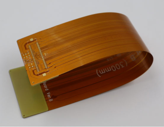
In Flexible PCBs (FPCs)
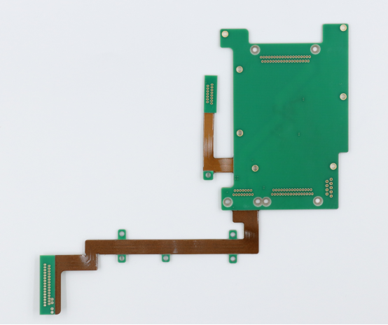
In flexible printed circuit boards (FPCs), polyimide film functions as the primary base substrate that supports copper circuitry. It forms the foundation upon which conductive traces are etched, allowing the circuit to bend, twist, or fold without damage. This flexibility is achieved without sacrificing electrical insulation or dimensional stability, making polyimide the ideal choice for compact and dynamic electronic assemblies.
A typical FPC stack-up consists of multiple thin layers arranged as follows:
Copper foil / Adhesive / Polyimide (PI) film / Coverlay.
The copper foil carries the circuit pattern.
The adhesive bonds the copper to the polyimide film.
The PI film acts as the dielectric and mechanical backbone.
The coverlay (a protective polyimide layer with adhesive) seals and protects the circuitry.
This multilayer arrangement produces circuits that are lightweight, bendable, and highly durable, ideal for applications such as camera modules, wearable devices, and foldable displays. Unlike rigid boards, FPCs made from polyimide film can withstand repeated flexing and thermal stress, maintaining reliable electrical connectivity over thousands of bending cycles.
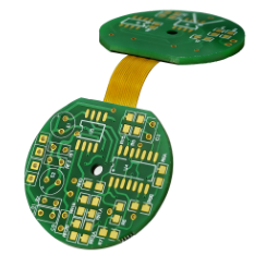
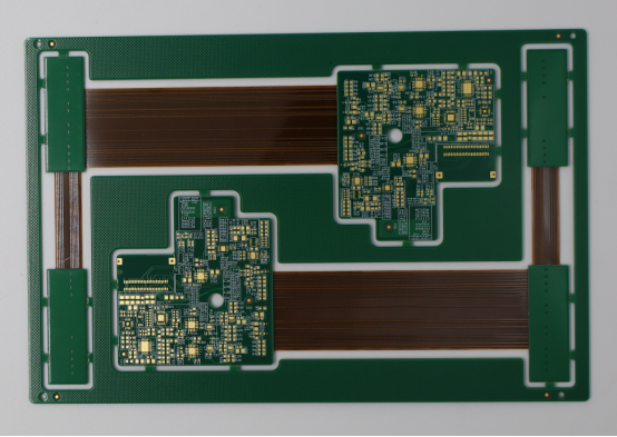
In Rigid-Flex PCBs
In rigid-flex PCB design, polyimide film bridges the gap between rigid and flexible zones, combining the strength of FR-4 with the flexibility of PI. The structure typically includes rigid layers made of FR-4 glass epoxy for component mounting, and flexible layers of polyimide film that interconnect these rigid sections.
A simplified integration process includes the following steps:
1. Form flexible layers using polyimide film laminated with copper foil.
2. Bond these layers between rigid FR-4 panels using prepreg or adhesive.
3. Drill vias and plate holes to create electrical connections between rigid and flex regions.
4. Apply protective coverlays on the flexible parts for insulation and durability.
This hybrid architecture allows designers to eliminate connectors and cables, reduce assembly complexity, and enhance signal integrity. Rigid-flex PCBs are commonly found in medical imaging systems, aerospace electronics, and high-end consumer devices, where space is limited and mechanical reliability is critical.
In High-Temperature or Aerospace Applications
Polyimide film’s thermal endurance and chemical stability make it indispensable in high-temperature, high-reliability environments. In aerospace and automotive systems, PCBs must survive continuous thermal cycling, vibration, and exposure to harsh conditions that would degrade conventional materials.
For example:
Satellites and avionics systems use polyimide-based flex circuits to ensure stable operation across extreme temperature ranges in vacuum environments.
Automotive control units and EV battery management boards rely on PI films to resist engine heat and fluctuating humidity.
Polyimide film maintains its electrical insulation, mechanical strength, and adhesion even under repeated heating and cooling cycles. Its resistance to oxidation and radiation further enhances its lifespan in demanding applications.
In essence, polyimide film enables long-term reliability in mission-critical PCBs, ensuring that performance remains consistent whether the board is operating in the stratosphere or under the hood of a vehicle.
Manufacturing and Processing of Polyimide-Based PCBs
Typical Fabrication Process
The fabrication of polyimide-based PCBs, especially flexible and rigid-flex designs, requires greater precision than traditional rigid FR-4 boards due to the thinness and flexibility of the materials. Each step must preserve dimensional accuracy and adhesion strength to ensure circuit reliability.
Step 1: Polyimide Film Lamination
The process begins with laminating a polyimide film that acts as the dielectric core. Depending on design requirements, the film may be adhesive-based or adhesive-less. During lamination, uniform heat and pressure are applied to bond the polyimide layer to copper foil or other substrates.
Step 2: Copper Foil Adhesion or Sputtering
Copper can be attached to the polyimide film through adhesive bonding or direct sputtering (adhesive-less method). Adhesive bonding is common in cost-sensitive designs, while sputtered copper layers provide superior peel strength, stability, and resistance to delamination in high-temperature applications.
Step 3: Circuit Etching and Drilling
Once laminated, the copper is patterned using photolithography and chemical etching to define fine conductive traces. Laser drilling or mechanical drilling is then performed to create vias or microvias that connect different layers. Polyimide’s dimensional stability and heat resistance allow for high-precision alignment even on very thin films, which is essential for high-density interconnect (HDI) flexible circuits.
Step 4: Coverlay Application and Stiffener Addition
A polyimide coverlay—a protective layer with adhesive—is applied over the etched circuitry to insulate and protect traces from mechanical wear and oxidation. For areas requiring rigidity (such as connector ends or component mounting zones), stiffeners made of FR-4, stainless steel, or additional polyimide are bonded to reinforce structural integrity.
Throughout fabrication, tolerances are tightly controlled, typically within ±25 µm, to ensure that flexible layers align precisely during lamination and assembly. This precision is critical for reliable performance under repeated flexing and thermal cycling.
Surface Finishing Options
Surface finishes protect exposed copper from oxidation and ensure strong solder joints during assembly. For polyimide-based PCBs, common finishes include:
ENIG (Electroless Nickel Immersion Gold):
The most popular finish for flexible PCBs. It offers excellent solderability, flatness, and corrosion resistance, and adheres well to copper without damaging the polyimide substrate.
OSP (Organic Solderability Preservative):
A thin organic layer that protects copper during storage and reflow. It is environmentally friendly and cost-effective, though less durable than ENIG under multiple heat cycles.
Immersion Tin or Immersion Silver:
These finishes provide good conductivity and reliable soldering for fine-pitch circuits. However, they require careful handling to prevent oxidation or tarnishing, especially in humid environments.
Each finish must be chosen based on application temperature, assembly process, and storage conditions, as polyimide films can expand slightly under heat—making adhesion strength and surface compatibility key design considerations.
Design Considerations
Designing PCBs with polyimide substrates involves balancing flexibility, mechanical strength, and electrical reliability.
Bending Radius and Trace Layout Rules:
The minimum bending radius typically ranges from 6 to 12 times the total thickness of the flex circuit. Traces should be routed perpendicular to the bend line with smooth curves instead of sharp angles to prevent copper cracking.
Adhesive vs. Adhesive-Less Films:
Adhesive-based films are easier to process and more cost-efficient, but the adhesive layer can reduce heat resistance and cause minor dimensional shifts. Adhesive-less films provide superior reliability for continuous or repeated flexing, making them ideal for wearable and aerospace applications.
Example – 180° Fold Application:
For designs requiring complete folding, engineers often use a reinforced polyimide hinge with staggered trace layouts to distribute mechanical stress evenly. The copper thickness is reduced near the fold zone to improve flexibility and prevent fatigue cracking during repeated bends.
By following these design and process guidelines, manufacturers can produce durable, high-precision polyimide-based PCBs that maintain electrical and mechanical performance across demanding environments and long operational lifespans.
Polyimide Film vs. Other PCB Materials
Comparison with FR-4
Polyimide (PI) film and FR-4 are two of the most common materials used in PCB manufacturing, but they serve different purposes. FR-4 is a glass-reinforced epoxy laminate widely used for rigid boards, while polyimide film is a flexible, heat-resistant polymer ideal for dynamic or high-reliability applications.
Property | Polyimide (PI) Film | FR-4 (Epoxy-Glass Laminate) |
|---|---|---|
Mechanical Rigidity | Flexible, bendable | Rigid, non-flexible |
Glass Transition Temperature (Tg) | ~360°C | ~130–170°C |
Flexibility | Excellent, suitable for dynamic bending | None (can crack under flex) |
Dielectric Loss | Low (≈ 0.002–0.004) | Moderate (≈ 0.02) |
Thermal Stability | Continuous use up to 260°C | Up to 130°C |
Cost | Higher | Lower |
When to choose PI over FR-4:
Use polyimide film when flexibility, high thermal endurance, or weight reduction are priorities—such as in flexible displays, aerospace systems, or compact wearable devices. In contrast, FR-4 remains the go-to material for standard rigid boards where mechanical stability and cost-efficiency are more important than flexibility.
In essence, FR-4 suits static, low-cost electronics, while polyimide is ideal for high-performance or mechanically dynamic applications.
Comparison with PET Film
While PET (polyester film) and PI (polyimide film) are both polymer-based substrates used in flexible circuits, their performance profiles are vastly different. PET is more affordable but less durable under heat and stress.
Property | Polyimide (PI) Film | PET (Polyester Film) |
|---|---|---|
Maximum Operating Temperature | 260°C continuous, 400°C short-term | 120°C (softens above 150°C) |
Chemical Resistance | Excellent (resists solvents and acids) | Moderate |
Mechanical Durability | Outstanding, maintains shape after flex cycles | Fair, deforms with repeated bending |
Cost | Higher | Lower |
Example Applications:
PET film is commonly used in membrane switches, touch panels, and low-cost flexible circuits where operating temperatures remain below 100°C.
Polyimide film, on the other hand, is preferred for dynamic flex circuits, rigid-flex PCBs, and automotive sensors, where high temperature and vibration resistance are essential.
Thus, PET is suitable for budget-friendly, low-stress environments, while polyimide ensures long-term performance under demanding conditions.
Cost and Performance Trade-Offs
Choosing between polyimide, FR-4, and PET ultimately depends on the balance between cost and reliability.
For high-reliability or mission-critical products—such as aerospace modules, medical implants, and automotive control systems—the higher upfront cost of polyimide film delivers long-term ROI through superior thermal stability, flexibility, and durability.
For mass-market consumer electronics—like toys, LED modules, or basic appliances—FR-4 or PET provides sufficient performance at a fraction of the cost.
A practical way to view the trade-off:
“Use polyimide when failure is not an option; use FR-4 or PET when cost efficiency matters most.”
By understanding these distinctions, PCB designers can select the optimal substrate that balances function, environment, and budget, ensuring both manufacturing efficiency and product reliability.
Applications of Polyimide Film in Modern Electronics
Consumer Electronics
Polyimide film is widely used in consumer electronics because it allows circuits to be thin, flexible, and lightweight without sacrificing durability. Key applications include:
Flexible displays: Polyimide-based flexible circuits enable foldable or rollable screens, maintaining electrical connectivity even under repeated bending.
Smartphones: PI films support compact, multilayer interconnects for cameras, touch sensors, and logic boards, helping reduce device thickness while improving reliability.
Camera modules: Tiny, high-density camera circuits rely on polyimide substrates to withstand heat during soldering and remain stable during device operation.
In these applications, polyimide film ensures long-term performance despite frequent mechanical stress and high-density design requirements.
Automotive and Industrial Systems
In automotive and industrial electronics, polyimide film enables boards that can withstand extreme temperatures, vibration, and chemical exposure. Typical applications include:
Sensor interconnects: Flexible PI circuits connect sensors to controllers in tight spaces, such as engine compartments or robotic arms.
Battery management PCBs: EV and hybrid vehicle batteries use polyimide-based flex circuits for reliable high-current connections that endure thermal cycling.
EV modules and industrial controllers: PI films allow compact, reliable routing of signals in high-voltage or high-temperature systems.
The material’s durability ensures that circuits continue to perform accurately even in harsh automotive or industrial environments.
Aerospace, Medical, and 5G Devices
Polyimide film is essential in high-reliability and high-frequency applications where conventional substrates cannot meet performance demands.
Aerospace: Satellite control boards and avionics rely on PI-based circuits to survive extreme thermal cycles, radiation exposure, and vibration in space missions.
Medical devices: Wearables, diagnostic tools, and implantable electronics use flexible polyimide circuits for biocompatibility, miniaturization, and reliability.
5G and high-frequency communications: PI substrates support low dielectric loss and high signal integrity, making them ideal for antennas, RF modules, and high-speed network boards.
In these sectors, polyimide film ensures consistent electrical performance, mechanical stability, and thermal endurance, enabling next-generation electronic systems that must perform flawlessly under demanding conditions.
Advantages and Limitations
Key Advantages
Polyimide film offers several significant advantages that make it a preferred material for flexible and rigid-flex PCBs:
High Flexibility and Tensile Strength:
Polyimide films can bend, twist, and fold repeatedly without cracking, while maintaining structural integrity. This makes them ideal for dynamic flex circuits in foldable devices, wearable electronics, and compact automotive modules.
Excellent Insulation and Thermal Endurance:
With a high dielectric strength and the ability to withstand continuous temperatures up to 260°C, polyimide film ensures stable electrical performance even under soldering or high-power operating conditions. Its chemical and thermal resistance allows it to endure harsh environments in automotive, aerospace, and industrial applications.
Supports Compact and Lightweight Designs:
The thin, lightweight nature of polyimide film enables miniaturized PCB layouts, reducing overall device size without compromising reliability. This property is critical for smartphones, flexible displays, and medical wearables where space and weight are limited.
These advantages collectively allow engineers to design high-density, high-reliability circuits that would be impossible with rigid FR-4 or PET substrates.
Limitations and Challenges
Despite its strengths, polyimide film presents several challenges that designers and manufacturers must address:
Higher Material Cost and More Complex Manufacturing:
Compared to FR-4 or PET, polyimide is more expensive, and its processing requires tighter control over temperature, pressure, and handling. This increases production complexity and initial investment.
Potential Dimensional Shift During Lamination:
Thin polyimide layers may experience minor expansion or contraction under heat and pressure, which can affect trace alignment and via registration. Precision equipment and careful process control are necessary to maintain high-density interconnect accuracy.
Need for Specialized Equipment in Multilayer FPC Production:
Manufacturing multilayer flexible or rigid-flex PCBs with polyimide film often requires laser drilling, automated lamination, and advanced alignment tools. These requirements limit its use in low-cost or simple PCB applications.
By understanding these limitations, designers can make informed decisions, balancing cost, complexity, and performance to maximize the benefits of polyimide-based PCB solutions.
Future Trends in Polyimide Film Technology
Emerging Developments
Polyimide film technology continues to evolve, driven by the demand for smaller, faster, and more thermally efficient electronics. One key development is the creation of ultra-thin and high-modulus PI films, which allow engineers to design miniaturized, high-density circuits without sacrificing mechanical strength. These films are particularly valuable in foldable devices, compact medical electronics, and aerospace modules, where space is at a premium.
Another trend is the development of thermally conductive or heat-dissipative polyimides. Traditional PI films are excellent insulators, but new formulations integrate ceramic fillers or modified polymers to improve heat transfer. This enables high-power devices and LED modules to maintain stable temperatures while ensuring circuit reliability, bridging the gap between flexibility and thermal management.
Sustainability and Green Manufacturing
Environmental considerations are becoming increasingly important in electronics manufacturing, and polyimide films are adapting to meet these demands. Halogen-free PI films are being introduced to reduce harmful emissions during production and disposal, aligning with RoHS and REACH compliance.
Additionally, manufacturers are exploring recycling and low-emission production methods for polyimide-based PCBs. Techniques such as solvent recovery, thermal depolymerization, and waste minimization help reduce environmental impact while maintaining high-quality substrates. These innovations support eco-friendly electronics without compromising the high-performance characteristics of polyimide film.
Integration with Next-Gen PCBs
Polyimide film is playing a pivotal role in next-generation electronics, particularly in flexible hybrid electronics (FHE), wearable devices, and printed sensors. Its combination of flexibility, thermal stability, and electrical reliability allows circuits to be integrated directly into textiles, thin displays, and compact medical sensors.
For example, wearable health monitors leverage polyimide-based flexible circuits for continuous motion and bending, while maintaining signal integrity. Similarly, printed sensors and smart textiles use PI films as a lightweight substrate that supports miniaturized circuits without limiting user comfort or device functionality.
In summary, the future of polyimide film lies in ultra-thin, thermally enhanced, and sustainable materials that enable innovative, flexible, and eco-conscious electronic solutions. Its adaptability ensures it will remain a cornerstone of advanced PCB design for years to come.
Conclusion
Polyimide film is a high-performance material that has transformed the design of flexible and rigid-flex PCBs. Its combination of thermal stability, mechanical flexibility, and electrical reliability allows engineers to create circuits that can bend, fold, and withstand harsh environments without compromising performance. From consumer electronics and wearable devices to automotive systems and aerospace applications, polyimide-based PCBs enable miniaturized, durable, and high-density designs that are not possible with traditional rigid materials like FR-4.
At PCBMASTER, we specialize in producing advanced polyimide-based PCBs that meet the highest standards of precision, reliability, and innovation. Our expertise ensures that every flexible or rigid-flex PCB performs consistently, even in demanding applications where failure is not an option.
Contact PCBMASTER for customized flexible PCB solutions and leverage the benefits of polyimide film to bring your next-generation electronic designs to life.
FAQs
What makes polyimide film different from FR-4 in PCB applications?
Polyimide film is flexible, heat-resistant, and lightweight, whereas FR-4 is a rigid glass-epoxy laminate. Polyimide can bend and fold repeatedly without cracking, making it ideal for flexible and rigid-flex PCBs, while FR-4 is better suited for static, rigid boards. Additionally, polyimide offers higher thermal stability and lower dielectric loss, which is essential for high-density and high-frequency circuits.
Can polyimide film be used in multilayer flexible circuits?
Yes. Polyimide film is commonly used in multilayer flexible and rigid-flex PCBs. Its dimensional stability and thermal endurance allow multiple layers to be laminated together with high precision. Adhesive or adhesive-less PI films can support complex interconnects, microvias, and high-density layouts, making them suitable for compact electronic devices.
How does temperature affect the performance of polyimide PCBs?
Polyimide film can operate continuously up to 260°C and tolerate short-term peaks near 400°C. This high thermal resistance ensures that electrical insulation, mechanical strength, and signal integrity remain stable even during soldering, reflow, or harsh operating conditions. Unlike other polymers, polyimide does not warp or delaminate under repeated thermal cycling.
What are the best design practices for flexible PCBs using polyimide film?
Key design practices include:
Maintaining a proper bending radius: Typically 6–12 times the circuit thickness.
Routing traces perpendicular to fold lines and using smooth curves to prevent cracking.
Choosing adhesive-less films for repeated flexing to improve durability.
Reinforcing critical areas with stiffeners or staggered trace layouts, especially for 180° folds.
These practices ensure mechanical reliability and long-term performance of flexible circuits.
Is polyimide film suitable for high-frequency or 5G PCB designs?
Yes. Polyimide film has a low dielectric constant (~3.4) and low dielectric loss, which preserves signal integrity at high frequencies. This makes it suitable for RF circuits, antennas, 5G modules, and high-speed interconnects, where stable electrical performance and minimal signal degradation are critical.

