


How to Choose the Right Printed Circuit Board Capacitor for Your Design
Choosing the right printed circuit board capacitor is a critical step in designing reliable and efficient electronic circuits. Capacitors play a key role in storing energy, filtering signals, and stabilizing voltage, and selecting the wrong type or rating can lead to performance issues, circuit instability, or even premature failure.
With a wide variety of capacitor types — including ceramic, electrolytic, tantalum, film, and supercapacitors — and numerous specifications like capacitance, voltage rating, and equivalent series resistance (ESR), designers need a systematic approach to ensure optimal performance for their PCB design. For example, a decoupling capacitor placed too far from a microcontroller may fail to suppress high-frequency noise effectively, while a bulk capacitor with insufficient voltage rating can cause power instability.
In this article, we will guide you through how to choose the right printed circuit board capacitor for your design. You will learn to evaluate capacitor specifications, understand different types and applications, consider environmental and layout factors, and balance cost with performance — helping you make informed decisions for both prototypes and mass production.
Understanding Capacitor Specifications
Capacitance Value
Capacitance, measured in Farads (F), determines a capacitor’s ability to store electrical charge. The higher the capacitance, the more energy the capacitor can store. Capacitance also affects signal behavior in circuits — for example, filtering high-frequency noise or maintaining voltage stability.
Example:
l A 0.1µF ceramic capacitor is commonly used for decoupling, providing a quick response to voltage fluctuations near an IC.
l A 1000µF electrolytic capacitor is used for bulk energy storage, such as smoothing the output of a power supply.
Key takeaway: Select a capacitance value based on the intended function — low capacitance for signal smoothing and high capacitance for energy storage.
Voltage Rating
The voltage rating indicates the maximum voltage a capacitor can safely handle. Choosing a capacitor with an appropriate voltage rating ensures reliability and prevents failure.
Guideline: Always select a capacitor with a voltage rating higher than the maximum circuit voltage, typically 20–50% above to provide a safety margin.
Comparison Example:
l Using a 16V-rated capacitor in a 12V circuit provides a 33% margin.
l Using a 25V-rated capacitor in the same circuit gives a 108% margin.
l A higher voltage rating increases reliability, though it may slightly increase size or cost.
Key takeaway: Never use a capacitor with a voltage rating below your circuit’s maximum voltage.
Tolerance
Tolerance represents the possible variation from the capacitor’s nominal value, usually expressed as ±%. Tolerance is crucial for precision circuits, where small deviations can affect performance.
Step-by-step Example:
l A 100µF capacitor has a ±10% tolerance.
l Minimum capacitance = 100µF × (1 – 0.10) = 90µF
l Maximum capacitance = 100µF × (1 + 0.10) = 110µF
l The actual capacitance in the circuit may vary between 90µF and 110µF.
Key takeaway: Choose tighter tolerance capacitors (e.g., ±5% or ±1%) for circuits that require precise timing or filtering.
Equivalent Series Resistance (ESR) and Ripple Current
Equivalent Series Resistance (ESR) is the internal resistance of a capacitor. High ESR can cause heat generation and reduce efficiency, especially in high-frequency or switching circuits.
Ripple current is the AC component flowing through the capacitor, generating heat proportional to ESR. Choosing low ESR capacitors ensures stable performance and longevity.
Example:
l In a switching power supply, a low ESR capacitor reduces heat buildup and maintains stable output voltage.
l Electrolytic capacitors with high ESR may fail prematurely in high-frequency applications, while ceramic or polymer capacitors perform better.
Key takeaway: Always consider ESR and ripple current ratings to prevent overheating and ensure reliable operation in demanding circuits.
Types of PCB Capacitors and Their Applications
Ceramic Capacitors
Pros: Ceramic capacitors are low cost, compact, and perform well at high frequencies, making them ideal for signal filtering and decoupling applications.
Cons: They have limited capacitance values, often below 1µF, and may exhibit the microphonic effect, where vibrations create electrical noise.
Example: A 0.1µF ceramic capacitor is commonly used for decoupling integrated circuits (ICs), providing immediate voltage stabilization near the IC power pins to reduce high-frequency noise.
Key takeaway: Ceramic capacitors are best suited for high-frequency decoupling, small signal filtering, and space-constrained PCB designs.
Electrolytic Capacitors
Pros: Electrolytic capacitors offer high capacitance values at low cost, making them suitable for bulk energy storage and power supply filtering.
Cons: They are larger in size, polarity-sensitive, and generally have a shorter lifespan compared to other capacitor types.
Example: In a DC power supply, 1000µF electrolytic capacitors smooth output voltage fluctuations and provide stable energy to the load.
Key takeaway: Electrolytic capacitors are ideal for low-frequency bulk storage and power smoothing but require attention to polarity and placement.
Tantalum Capacitors
Pros: Tantalum capacitors are compact, stable, and reliable for low-voltage applications, making them useful in space-sensitive designs like mobile devices.
Cons: They can fail short-circuit if subjected to excessive voltage, incorrect polarity, or poor surge protection.
Example: A 10µF tantalum capacitor can provide stable voltage decoupling in a smartphone’s power rail without taking up much PCB space.
Key takeaway: Tantalum capacitors are suitable for precision low-voltage circuits but must be carefully selected to avoid overvoltage failures.
Film and Supercapacitors
Film Capacitors:
Pros: Low ESR, excellent stability, and long lifespan.
Applications: Commonly used in audio circuits or signal conditioning where stability is critical.
Supercapacitors:
Pros: Extremely high capacitance for energy storage.
Applications: Provide backup power for embedded systems, memory retention, or energy harvesting applications.
Example: A supercapacitor in an embedded system can maintain system memory during power interruptions, ensuring data integrity until the main supply is restored.
Key takeaway: Film capacitors excel in precision signal and audio circuits, while supercapacitors are best for temporary energy storage or backup power applications.
Key Points for Selecting PCB Capacitors
After reviewing the types and specifications of PCB capacitors, it is important to evaluate environmental and operating conditions that affect performance. Factors like temperature, humidity, mechanical stress, and vibration can directly impact a capacitor’s reliability and lifespan.
Environmental and Operating Conditions
Selecting the right PCB capacitor requires careful consideration of the environment and operating conditions. Factors such as temperature, humidity, and mechanical stress directly affect capacitor performance, reliability, and lifespan.
Temperature Range
Temperature variations can change capacitance values and affect long-term reliability. High temperatures may accelerate aging, cause dielectric breakdown, or trigger capacitance drift.
Example: For automotive or industrial PCBs exposed to high heat, designers often select high-temperature ceramic or tantalum capacitors rated up to 125°C or 150°C, ensuring stable performance under extreme conditions.
Key takeaway: Always check the operating temperature range and choose capacitors with sufficient temperature margins to prevent failure.
Humidity and Moisture Sensitivity
Capacitors, especially ceramic and electrolytic types, can absorb moisture, which may lead to corrosion, leakage, or electrical instability. The packaging type — sealed vs. open — also impacts moisture resistance.
Step-by-step: Evaluating Moisture Sensitivity Level (MSL)
1. Identify the capacitor type and packaging.
2. Refer to the IPC/JEDEC MSL rating for the component.
3. Determine whether the expected humidity and storage conditions require higher protection.
4. Select capacitors that comply with the required MSL rating to prevent moisture-related failures.
Key takeaway: Understanding moisture sensitivity helps reduce leakage, prevent failures, and extend capacitor lifespan.
Mechanical Stress and Vibration
Capacitors can be damaged by board flexing, vibration, or shock, which may cause cracks, solder joint failure, or electrical discontinuity. Choosing components with mechanical resilience is crucial in high-vibration environments.
Example: In automotive or industrial equipment:
l Ceramic capacitors are small and stable but can crack under severe vibration.
l Polymer or film capacitors provide better mechanical robustness for high-vibration applications.
Key takeaway: Evaluate the mechanical and vibration tolerance of capacitors, particularly for boards exposed to movement, shock, or vibration.
PCB Layout Considerations
The layout of PCB capacitors plays a critical role in signal integrity, noise reduction, and overall circuit performance. Proper placement, footprint selection, and configuration can prevent voltage fluctuations, reduce electromagnetic interference (EMI), and extend component lifespan.
Placement for Decoupling and Noise Reduction
Capacitors used for decoupling or bypassing should be placed as close as possible to IC power pins to provide immediate current during fast switching events. This minimizes voltage drops and reduces high-frequency noise.
Example: Placing 0.1µF ceramic capacitors directly adjacent to a microcontroller’s VCC/GND pins ensures effective noise suppression and stable operation.
Key takeaway: Proximity is critical — the shorter the connection path, the better the decoupling performance.
Footprint and Mounting Style
Capacitor footprint and mounting style influence board space, assembly method, and thermal performance. Designers typically choose between:
l Surface-mount devices (SMD): Compact, suitable for automated pick-and-place assembly, ideal for high-density PCBs.
l Through-hole components: Larger, mechanically robust, easier to replace or manually solder, often used for power applications.
Considerations:
l High-density boards often favor SMD capacitors.
l Through-hole capacitors may be better for high-current or high-vibration applications.
Key takeaway: Select the mounting style based on space constraints, assembly method, and mechanical requirements.
Parallel and Series Configurations
Sometimes a single capacitor does not meet the desired capacitance, voltage rating, or ESR requirements. Designers can combine capacitors in parallel or series to achieve the target specifications.
Step-by-step Example:
1. Determine required capacitance and voltage rating for the circuit.
2. For higher capacitance, connect multiple capacitors in parallel: 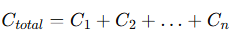
3. For higher voltage tolerance, connect capacitors in series: 
4. Evaluate ESR: Parallel configuration reduces ESR, while series increases voltage handling.
Key takeaway: Combining capacitors allows designers to fine-tune electrical performance without switching to a single larger component.
Reliability and Lifespan Considerations
Ensuring the reliability and longevity of PCB capacitors is essential for stable circuit operation, especially in industrial, automotive, and high-performance electronics. Designers must account for aging, failure modes, and compliance standards when selecting components.
Aging and Degradation
Capacitors naturally degrade over time, with performance impacted by temperature, voltage, and environmental conditions.
l Ceramic capacitors may experience capacitance drift over long-term operation, particularly in high-temperature environments.
l Electrolytic capacitors can lose electrolyte, causing reduced capacitance, increased ESR, and eventual failure.
Example: For industrial PCBs expected to operate continuously for years, selecting high-temperature rated or long-life electrolytic capacitors ensures stable operation and reduces maintenance costs.
Key takeaway: Evaluate the rated lifespan of capacitors and choose components that maintain performance under expected operating conditions.
Failure Modes
Common capacitor failures include:
l Short-circuit: Often caused by dielectric breakdown.
l Open-circuit: Loss of connection or broken internal structure.
l Leakage: Gradual loss of insulation leading to current leakage and heat buildup.
How to minimize risk:
l Select capacitors with appropriate voltage and temperature ratings.
l Use series/parallel configurations when necessary to avoid exceeding specifications.
l Consider mechanical robustness to prevent cracking or solder joint failure.
Key takeaway: Understanding failure modes helps engineers prevent critical circuit failures and improve overall PCB reliability.
Compliance and Standards
Capacitor selection must consider regulatory and industry standards, including:
l RoHS (Restriction of Hazardous Substances): Limits use of hazardous materials like lead.
l REACH: Ensures chemical safety in components.
l IPC standards: Define performance, testing, and quality benchmarks.
Importance: Compliance ensures that PCB capacitors are safe, environmentally friendly, and suitable for regulated products. Non-compliant components may fail certification or cause legal and safety issues.
Key takeaway: Always verify standards compliance when sourcing capacitors, especially for commercial, automotive, or industrial applications.
Cost vs. Performance Trade-offs
Selecting the right PCB capacitor is not only about technical performance; it also requires balancing cost and design requirements. Making informed trade-offs ensures that the capacitor meets circuit needs without unnecessary expenses.
Budget Constraints
Engineers often face budget limitations, requiring careful consideration of which capacitor types and specifications to use.
Example:
l For bulk decoupling, ceramic capacitors are cost-effective, small, and provide sufficient high-frequency noise suppression.
l For precision filtering or low-voltage analog circuits, tantalum capacitors may be more appropriate despite higher cost, due to their stability and compact size.
Key takeaway: Evaluate both performance needs and budget to select capacitors that provide reliable operation without overspending.
Over-Specifying vs. Under-Specifying
Choosing a capacitor with excessive voltage, capacitance, or ESR may increase cost, board size, or reduce efficiency. Conversely, under-specifying can lead to premature failure or circuit instability.
Step-by-step guide to optimize cost while meeting design requirements:
1. Identify the minimum required capacitance, voltage rating, and ESR for your application.
2. Select a capacitor type that meets performance specifications without unnecessary overrating.
3. Consider parallel or series configurations to fine-tune values instead of using a single oversized component.
4. Review supplier cost options, balancing quality, lifespan, and availability.
Key takeaway: Properly matching capacitor specifications to actual circuit needs reduces cost and avoids overengineering while ensuring reliable operation.
Conclusion and Practical Tips
Selecting the right PCB capacitor requires careful consideration of multiple factors, including type, capacitance, voltage rating, ESR, environmental conditions, PCB layout, reliability, and cost. Each factor plays a critical role in ensuring that your circuit operates reliably, maintains performance, and avoids premature failures. Evaluating these criteria early in the design phase allows engineers to make informed decisions, optimize component placement, and prevent costly mistakes during prototyping or production.
Example: Creating a capacitor selection checklist that lists required capacitance, voltage, ESR, temperature range, and mounting type can streamline the design process, improve consistency across projects, and help maintain compliance with industry standards.
For any questions or guidance on selecting the right capacitors for your PCB design, PCBMASTER, a professional PCB supplier, is ready to provide expert advice and support. Consulting with experienced suppliers early can save time, reduce costs, and ensure the success of your electronic designs.
FAQs
How do I choose the right capacitor for filtering versus decoupling?
For filtering, select capacitors with higher capacitance to smooth voltage ripple in power supplies. Electrolytic capacitors are commonly used for bulk filtering due to their high capacitance. For decoupling, choose low-value, high-frequency capacitors such as 0.01–0.1 µF ceramics placed close to IC power pins. This reduces voltage spikes and minimizes noise.
Can I replace a ceramic capacitor with a tantalum one in my design?
Tantalum capacitors are stable and compact, suitable for low-voltage, high-reliability applications, but they are polarity-sensitive and can fail short-circuit if misused. Ceramic capacitors are inexpensive, non-polar, and perform well at high frequencies. Replacement is possible if the voltage, capacitance, and frequency requirements match, but always verify ESR, tolerance, and safety margins.
What is the impact of ESR on capacitor performance in switching circuits?
Equivalent Series Resistance (ESR) affects heat generation and voltage ripple in high-frequency circuits. Low-ESR capacitors are preferred for switching power supplies to reduce power loss and improve efficiency. High-ESR capacitors may overheat and degrade faster. Step-by-step: Check the circuit ripple current, select a capacitor with ESR rating below the maximum allowable, and verify thermal performance.
How do temperature and humidity affect PCB capacitor lifespan?
High temperatures accelerate aging and capacitance drift, while humidity can cause leakage or corrosion, especially in open-packaged capacitors. Selecting high-temperature-rated components and checking Moisture Sensitivity Level (MSL) for humid environments ensures reliable long-term operation.
Are surface-mount capacitors better than through-hole for high-frequency applications?
Surface-mount devices (SMD) are generally better for high-frequency applications due to shorter leads, lower parasitic inductance, and compact size, which improve signal integrity. Through-hole capacitors may be preferred for mechanical strength or high-current applications but can introduce additional inductance at high frequencies.

