What Is a PCBA Functional Tester and How It Ensures Product Reliability
In modern electronics manufacturing, testing is essential to ensure every PCBA performs reliably. A small defect—like a weak solder joint or faulty signal—can lead to product failures and costly recalls.
A PCBA functional tester verifies whether a completed circuit board works as designed by simulating real operating conditions, applying input signals, and measuring output responses. Unlike basic visual or electrical tests, it checks the actual performance of the assembled board.
By identifying hidden issues before shipment, functional testing helps manufacturers improve quality, enhance reliability, and build customer trust.
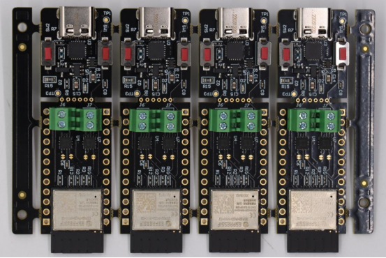
What Is a PCBA Functional Tester?
Definition and Purpose
A PCBA Functional Tester (FCT) is a specialized testing system used to verify that a fully assembled printed circuit board (PCBA) performs exactly as designed when operating under simulated real-world conditions. It is not a visual inspection or a design verification step, but rather the final stage of quality control before the product leaves the factory.
The primary purpose of a PCBA functional tester is to confirm that every electrical and software-driven function of the board operates correctly. It helps manufacturers detect functional faults, such as signal timing errors, power fluctuations, or firmware malfunctions, that cannot be found through earlier tests like AOI (Automated Optical Inspection) or ICT (In-Circuit Testing).
In simple terms, while ICT checks whether components are properly installed and connected, the functional tester asks a more practical question:
“Does this PCBA actually work the way the end user expects it to?”
By validating full operational performance, PCBA functional testing ensures the product’s reliability, safety, and long-term stability before shipment.
Core Components
A typical PCBA functional tester includes several integrated components that work together to simulate and evaluate the board’s behavior under real conditions:
1. Test Fixture
The fixture serves as both a mechanical and electrical interface between the PCBA and the testing system. It securely holds the board in place and ensures reliable, repeatable contact with test points, connectors, and other interfaces during testing. By maintaining stable connections, the fixture helps guarantee accurate test results and prevents damage to sensitive components. Depending on the production setup, fixtures can be manual, requiring operator handling, or automated, using pneumatic or motorized mechanisms to support high-throughput testing in automated production lines.
2. Measurement & Control Instruments
These instruments simulate various input signals—such as voltage, current, or communication protocols including UART, SPI, I²C, and CAN—to replicate real-world operating conditions. At the same time, they measure the corresponding output responses from the PCBA to verify that the board functions as intended. In more advanced setups, the instruments can dynamically adjust signal parameters, allowing engineers to evaluate the board’s performance and stability under different load or environmental conditions.
3. Software Interface
The test software plays a central role in automating the entire testing process. It controls the instruments, executes test procedures, and collects real-time data from the PCBA. The software then compares the measured values against predefined specifications, automatically determining pass or fail results. In modern systems, test results are also stored in databases, providing full traceability and enabling data analytics that support continuous quality improvement and informed decision-making.
4. Load and Power Systems
Power and load systems supply stable voltages and configurable load conditions to accurately replicate real operating environments for the PCBA. They enable engineers to evaluate the board’s performance under stress, such as high current demands or fluctuating voltage levels.
When combined with other testing components, these systems create a closed-loop environment that closely mimics how the PCBA will behave within the final product, ensuring reliable and comprehensive functional verification.
Example Application
Consider a home appliance controller, such as the main PCB used in a washing machine. During functional testing:
1. The controller board is placed in the test fixture and connected to simulated inputs — like start buttons or water-level sensors.
2. The tester sends these signals while monitoring the outputs, such as LED indicators, motor drivers, and communication with the main display.
3. If pressing the “Start” button activates the correct motor response and the communication interface returns the expected signal, the test passes.
If any output deviates from the expected response, the system immediately flags it for rework.
This process ensures that every shipped controller board functions correctly in real-world use, preventing costly failures once it reaches the customer.
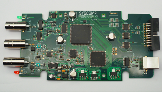
How a PCBA Functional Tester Works
Step-by-Step Testing Process
A PCBA functional tester operates by simulating real-world conditions and verifying that a circuit board responds correctly. The testing process can be broken down into clear, extractable steps:
1. Mount the PCBA on the fixture
Begin by securing the PCBA in a test fixture that offers both mechanical support and reliable electrical connections. It is essential to ensure that all contact points, connectors, and interfaces are properly aligned, as accurate positioning guarantees consistent test results and prevents potential damage to the board during the testing process.
2. Connect power and load systems
Provide the PCBA with a stable power supply and configurable load conditions to closely replicate its actual operating environment. Many testers are equipped with programmable power sources, allowing engineers to simulate voltage fluctuations or high-current scenarios and assess how the board performs under different stress conditions.
3. Apply simulated signals or operational inputs
Input signals are designed to mimic real-world conditions, including sensor data, button presses, or communication messages. The tester can also adjust signal levels, frequency, or timing, allowing engineers to evaluate how the PCBA performs under various stress conditions and ensuring reliable operation in actual use.
4. Measure responses through sensors or instruments
Collect real-time data on the PCBA’s electrical outputs, functional reactions, and communication responses. This includes measuring key variables such as voltage, current, relay activation, LED status, and digital signals, providing a comprehensive view of the board’s performance during testing.
5. Compare real-time data to predefined specifications
The test software evaluates whether the measured outputs fall within the board’s design tolerances. Any deviations from these specifications are automatically flagged as a fail, while behaviors that conform to the expected performance are marked as pass, enabling quick and accurate assessment of the PCBA’s functionality.
6. Record results automatically
All test data is logged to ensure full traceability and support future analysis. This information can be integrated into MES (Manufacturing Execution Systems) or ERP systems, allowing manufacturers to monitor quality trends, identify recurring issues, and make data-driven decisions for continuous improvement.
7. Flag deviations and generate reports
Immediate alerts allow engineers and operators to quickly address failures through rework or detailed failure analysis. Additionally, generated reports provide actionable insights for engineering, quality, and production teams, supporting informed decision-making and continuous improvement across the manufacturing process.
By following this step-by-step process, functional testers ensure that every PCBA leaving the production line meets both design and performance standards.
Typical Test Parameters
A PCBA functional tester evaluates multiple types of parameters to confirm the board’s operational integrity:
Electrical Parameters: voltage, current, resistance, and frequency measurements ensure components and circuits are operating correctly.
Functional Parameters: monitor input/output responses, relay switching behavior, LED indicators, and other device-specific operations.
Communication Parameters: verify proper data transmission over protocols such as UART, SPI, I2C, CAN, or Ethernet.
Testing multiple parameters ensures that the board will function reliably in real-world applications and under various environmental conditions.
Types of Functional Test Systems
PCBA functional testers vary depending on production volume, automation requirements, and product complexity:
Manual Bench Systems
Manual bench systems are ideal for low-volume production or R&D environments, where flexibility and direct control over testing are essential. They require operator intervention for tasks such as mounting the PCBA, applying input signals, and performing measurements, making them particularly suitable for prototyping and small-batch testing.
Semi-Automated Systems
Semi-automated systems utilize pneumatic or motorized fixtures to achieve faster and more consistent testing compared to fully manual setups. They strike a balance between automation and flexibility, making them well-suited for medium-volume production where efficiency and reliability are both important.
Fully Automated Test Stations
Fully automated test stations are integrated into high-volume production lines, often featuring robotic handling and conveyor systems to streamline the testing process. They connect directly to MES databases for automatic logging, traceability, and data analytics. These systems deliver the highest throughput while ensuring consistent quality assurance across large production volumes.
By selecting the right type of functional tester, manufacturers can optimize testing efficiency while ensuring all PCBAs meet strict quality and reliability standards.
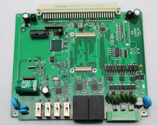
How Functional Testing Ensures Product Reliability
Verifies Real-World Functionality
Functional testing ensures that a PCBA operates correctly under real-world conditions. Unlike in-circuit testing (ICT) or automated optical inspection (AOI), which mainly check component placement or electrical continuity, a PCBA functional tester simulates actual operating scenarios. The system applies real input signals, power levels, and environmental conditions while monitoring outputs in real time. This allows it to detect logic errors, timing issues, or unexpected interactions between components that other testing methods might miss. For instance, a communication protocol such as I2C may appear functional in isolation but fail when multiple signals occur simultaneously. Functional testing identifies these issues before the board leaves the factory, ensuring it behaves as intended in practical applications.
Detects and Prevents Latent Defects
Latent defects are subtle problems that do not show up immediately but can cause early-life failures in the field. Functional testing helps identify these hidden issues by evaluating the board under stress conditions, such as fluctuating voltages, high currents, or temperature variations. For example, a temperature-sensitive sensor may have a slight calibration error that escapes ICT detection. Functional testing catches this error before shipment, preventing potential product failures. By identifying marginal performance issues early, manufacturers can reduce costly rework and avoid warranty claims.
Reduces Warranty and Field Failures
Implementing functional testing has a clear impact on product reliability and customer satisfaction. Boards that undergo functional testing generally show lower defect return rates compared to boards tested only with ICT or AOI. Fewer field failures lead to reduced warranty claims, lower support costs, and fewer production disruptions. Consistently delivering reliable products also enhances brand reputation and builds customer trust, which is especially important in industries such as automotive, medical devices, and industrial electronics.
Supports Compliance and Traceability
Functional testing helps manufacturers meet industry standards such as ISO 9001, IPC-A-610, and IATF 16949. Modern functional testers automatically log test results, including pass/fail status, signal measurements, and operational parameters. This data traceability enables manufacturers to track individual PCBA performance, analyze trends, and provide documented proof of quality for audits or customer requirements. Combining real-world validation, latent defect detection, warranty reduction, and compliance tracking, functional testing becomes a cornerstone of high-quality, reliable PCBA manufacturing.
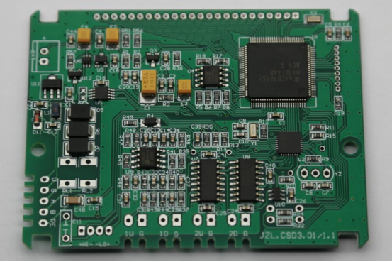
Comparison With Other PCB Testing Methods
In-Circuit Testing (ICT) vs. Functional Testing (FCT)
In-circuit testing (ICT) and functional testing (FCT) are both essential steps in PCB quality assurance, but they focus on different aspects of board verification.
ICT primarily checks electrical continuity and the correctness of individual components. It ensures that resistors, capacitors, diodes, and integrated circuits are correctly placed and electrically connected. For example, ICT can detect an open circuit caused by a missing solder joint or a short between adjacent pins.
Functional testing, on the other hand, goes beyond individual components to validate the full operational behavior of the PCBA. It simulates real-world inputs and monitors outputs to confirm that the board functions as intended. While ICT can identify assembly or component errors, FCT ensures that the board can perform all its designed functions under realistic operating conditions. In short, ICT verifies that the board is built correctly, while FCT verifies that it works correctly.
AOI/X-ray Inspection vs. Functional Testing (FCT)
Automated Optical Inspection (AOI) and X-ray inspection are used to detect physical defects on a PCB.
AOI checks for missing or misaligned components, solder bridges, and surface defects, while X-ray inspection can identify hidden soldering issues, such as voids in BGA or QFN packages. These methods are highly effective for detecting visual and structural assembly defects, but they do not assess whether the board performs its intended functions.
Functional testing complements AOI and X-ray by focusing on electrical and logic performance. It identifies issues such as firmware errors, timing mismatches, or communication faults that cannot be detected visually. Together, these testing methods are complementary rather than interchangeable: physical inspections ensure assembly quality, and functional testing ensures operational reliability.
Comparison Table
The differences between AOI, ICT, and FCT can be summarized as follows:
Test Method | Focus | Detects | Production Stage |
|---|---|---|---|
AOI | Visual defects | Misalignment, solder issues | After SMT |
ICT | Electrical | Opens, shorts, wrong component values | Mid-process |
FCT | Functional performance | Logic errors, timing issues, software faults | Final stage |
This table highlights that each testing method targets different defect categories. AOI identifies physical issues, ICT verifies component-level electrical integrity, and FCT ensures the board functions as intended. By combining these approaches, manufacturers can achieve comprehensive PCB quality assurance, reduce the risk of failures in the field, and improve overall product reliability.
Types of PCBA Functional Testers
Manual Testers
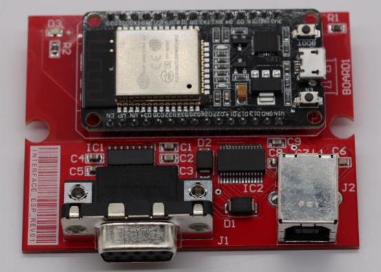
Manual PCBA functional testers are the simplest form of testing systems, designed for low-volume production, prototyping, or R&D environments. These systems are relatively low-cost and highly flexible, allowing engineers to adjust the test setup quickly for different PCB designs. The accuracy and consistency of manual testers, however, depend heavily on the operator’s skill.
For example, precise placement of test probes or correct sequence execution is essential to ensure valid results. Despite this limitation, manual testers remain a practical choice for development stages or small production runs where full automation is not cost-effective.
Semi-Automated Systems
Semi-automated functional testers strike a balance between manual operation and full automation. They often incorporate pneumatic or motorized fixtures, enabling faster and more repeatable connections between the PCBA and test instruments. These systems reduce operator dependence, improving both efficiency and accuracy while maintaining flexibility for multiple product types.
Semi-automated testers are ideal for medium-volume production, where some automation is beneficial but full robotic integration may not be justified. They can handle more complex boards than manual testers while still being cost-conscious.
Fully Automated Testers
Fully automated functional testers are designed for high-volume manufacturing and offer the highest levels of throughput and repeatability. These systems integrate robotic handling, conveyors, and programmable fixtures to minimize human intervention.
The testing process, including mounting, signal application, measurement, and result logging, is fully controlled by software, ensuring consistent quality across large production batches.
Fully automated testers also often connect to MES or ERP systems, enabling real-time data logging, traceability, and analytics. This type of system is essential in industries where product reliability and efficiency are critical, such as automotive electronics or medical devices.
Application Examples
PCBA functional testers are used across a wide range of industries and product types. For instance, automotive ECUs require functional testing to verify engine control, braking systems, or safety features.
Telecom modules rely on testers to ensure proper signal processing and communication protocol handling.
In the medical instrument sector, functional testing validates sensors, displays, and safety-critical electronics.
Even consumer devices, such as smart home controllers or wearable electronics, benefit from functional testing to confirm operational performance before shipment.
By selecting the appropriate type of tester — manual, semi-automated, or fully automated — manufacturers can match their production volume, budget, and reliability requirements while ensuring every PCBA functions as intended.
Key Considerations When Choosing a Functional Tester
Product Complexity and Interface Requirements
When selecting a PCBA functional tester, the complexity of the product is a primary consideration. Boards with mixed analog and digital signals or multiple subsystems require testers that can handle diverse signal types accurately.
The tester must also support the communication protocols used by the PCBA, such as UART, SPI, I2C, CAN, or Ethernet. For example, a telecommunications module may need precise timing verification for SPI and I2C buses, while an automotive ECU requires robust CAN protocol testing.
Choosing a tester that matches the board’s electrical and functional complexity ensures accurate testing results and reliable quality control.
Automation Level and Scalability
The automation level of the tester directly affects production efficiency and throughput. Manual testers are flexible but operator-dependent, whereas semi-automated and fully automated systems provide faster and more consistent testing.
Manufacturers should also consider scalability: the ability to handle future product variations or increased production volumes without major redesigns.
For instance, a modular semi-automated tester might allow quick fixture changes for different PCBA models, while a fully automated tester can be expanded with additional robotic arms or measurement modules as production grows.
Data Integration and Analysis
Modern functional testers should offer integration with MES (Manufacturing Execution Systems) or ERP platforms. This capability allows real-time logging of test results, pass/fail status, and operational parameters, providing full traceability of each PCBA. Data integration also enables detailed performance analysis, helping engineers identify trends, detect recurring faults, and optimize manufacturing processes.
For example, analyzing historical test data might reveal that a particular component consistently causes timing errors, prompting process improvements or design adjustments.
Cost-Benefit Analysis
Finally, cost is a key factor when choosing a functional tester. While high-end automated systems may require significant upfront investment, they often reduce long-term costs by minimizing rework, scrap, and warranty claims.
Conversely, manual testers have lower initial costs but can increase labor dependency and potential errors in high-volume production. Evaluating the return on investment (ROI) involves comparing tester acquisition costs against the savings from improved yield, reduced failures, and faster throughput. This ensures that the chosen solution is both economically viable and technically effective.
Future Trends in PCBA Functional Testing
Smart and Connected Testing
One of the most significant trends in PCBA functional testing is the adoption of smart, IoT-enabled testers. These systems can collect real-time data from multiple test stations and allow remote monitoring and control of testing operations. For example, a manufacturer with multiple production lines can track performance metrics, detect anomalies, and adjust test procedures without being physically on-site. IoT integration also enables centralized data analysis, providing a holistic view of product quality across different facilities and reducing downtime caused by equipment issues or test failures.
AI-Driven Fault Analysis
Artificial intelligence and machine learning are increasingly being applied to predictive fault detection in functional testing. By analyzing historical test data, AI models can identify patterns that indicate potential failures, even before they occur. For instance, if certain voltage fluctuations consistently precede logic errors, the system can flag boards for closer inspection. This approach allows manufacturers to anticipate defects, optimize test sequences, and improve first-pass yield, rather than relying solely on post-test failure identification. AI-driven analysis also accelerates root-cause investigations, helping engineers implement design or process improvements faster.
Adaptive and Self-Optimizing Test Systems
The next generation of functional testers is moving toward adaptive and self-optimizing systems. These testers can automatically adjust test parameters based on live feedback from the PCBA under test. For example, if a particular signal shows unexpected variability, the system can modify timing or load conditions to verify board behavior under different scenarios. This adaptability not only improves test accuracy but also enhances production efficiency, reduces false failures, and increases overall yield. By continuously learning from test data, self-optimizing systems help manufacturers maintain high quality standards even as products and designs evolve.
These trends indicate that PCBA functional testing is evolving from a purely reactive quality assurance step into a proactive, data-driven process. Smart connectivity, AI analysis, and adaptive automation collectively enable faster testing, higher reliability, and better insights into manufacturing performance, setting the stage for the next generation of electronics production.

Conclusion
PCBA functional testing represents the final and most comprehensive stage of validation in electronics manufacturing. It ensures that every printed circuit board assembly not only meets design specifications but also performs reliably under real-world conditions. By simulating operational scenarios, verifying electrical and logic functions, and detecting latent defects, functional testing reduces manufacturing risks, prevents field failures, and strengthens customer confidence.
Adopting automation and data-driven testing strategies further enhances the benefits of functional testing. Automated systems improve consistency and throughput, while integration with MES or AI-driven analytics allows manufacturers to track performance, identify trends, and optimize processes continuously. This proactive approach ensures that issues are caught early, production efficiency is maximized, and product quality remains consistently high.
At PCBMASTER, strict functional testing protocols are implemented to guarantee that every PCBA leaving the production line meets the highest quality standards. Through rigorous validation and smart testing strategies, PCBMASTER ensures reliable, high-performance PCBA solutions that customers can trust for demanding applications.
FAQs
What’s the difference between functional testing and ICT in PCB manufacturing?
In-circuit testing (ICT) and functional testing (FCT) serve different purposes in PCB quality assurance.
ICT primarily checks electrical connectivity and component correctness, identifying issues like open circuits, shorts, or incorrectly placed components. However, it does not verify whether the board actually performs its intended functions.
Functional testing, on the other hand, validates the overall operational performance of a PCBA by simulating real-world conditions. It confirms that the board responds correctly to inputs, executes logic and timing functions properly, and handles communication protocols and software as designed.
Can one functional tester support multiple product types?
Yes, a single functional tester can often support multiple PCB designs if it is flexible and modular. This typically involves using interchangeable test fixtures and configurable software scripts to adapt to different board layouts, signal types, and communication protocols. Semi-automated and fully automated testers are particularly effective in handling diverse products, allowing manufacturers to test multiple PCBA variants without extensive reconfiguration.
How is a PCBA test fixture designed and maintained?
A PCBA test fixture is custom-built to align precisely with the PCB layout, providing secure mechanical support and reliable electrical contact at all test points. Fixtures can be manual, pneumatic, or motorized depending on production needs. Regular maintenance is critical: worn probes, misaligned connectors, or debris can cause inaccurate measurements or false failures. Proper cleaning, calibration, and periodic inspection ensure consistent performance and reliable test results throughout the production cycle.
What kinds of defects can functional testing detect?
Functional testing identifies defects that other methods might miss. These include logic or software errors, such as incorrect firmware operation or timing issues; electrical performance problems, like voltage drops or current fluctuations; and functional failures under stress, where components fail under high load, temperature variations, or simultaneous signal conditions. It also uncovers latent defects that could cause early-life failures in the field, providing an extra layer of quality assurance beyond visual or in-circuit tests.
How does automation improve consistency in functional testing?
Automation enhances both the accuracy and repeatability of functional testing. Robotic fixtures, conveyors, and automated signal generation reduce human error and ensure that each test is executed with the same precision. Automated systems also collect and log data in real time, enabling traceability, trend analysis, and proactive defect detection. As a result, manufacturers achieve higher throughput, improved first-pass yield, and reduced rework, while maintaining consistent product quality across large production volumes.
