


Essential Guide to PCB Countersinks Design and Manufacturing Insights
Introduction
These seemingly minor features on a PCB are crucial for ensuring stable assembly and sleek, thin designs in electronic products.
In the world of PCB design, countersinks and counterbores might be small features, but they play an indispensable role in ensuring a perfect fit between the board and its housing, while preventing component interference. From smartphones and medical devices to automotive electronics, the design of these specialized holes directly impacts a product’s overall thickness, stability, and aesthetic appeal. Countersinks are also used for aesthetic purposes, as they contribute to a clean and professional appearance.
Introduction to PCB Countersinks
PCB countersinks are an essential feature in modern printed circuit board (PCB) design, providing both mechanical and aesthetic benefits. A countersink hole, sometimes referred to as a countersunk hole, is a cone-shaped hole drilled into the PCB to allow a flat head screw or countersunk screw to sit flush with the surface of the board. This design ensures that the screw head does not protrude above the PCB surface, which is critical for achieving a smooth, streamlined assembly and preventing interference with other components or enclosures.
The primary function of a countersink hole is to create a secure and stable mounting point, enhancing the overall assembly quality and reliability of the PCB. By allowing screws to sit flush with the surface, countersink holes contribute to a more compact and professional-looking product, which is especially important in applications where space is limited or where a sleek appearance is desired. In PCB design, the correct use of countersink holes is vital for ensuring that the board can be securely fastened without compromising its structural integrity or functionality.
Understanding how and when to use countersink holes is crucial for any designer aiming to optimize PCB assembly and achieve high-quality, reliable results.
Types of Holes in PCB Manufacturing
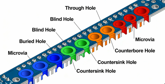
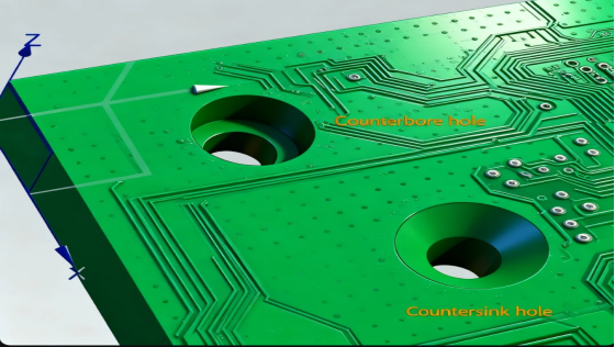
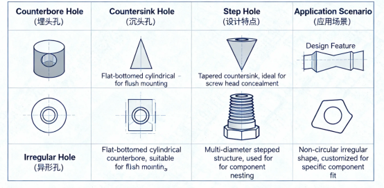
PCB manufacturing involves the use of various types of holes, each designed to accommodate specific fasteners and components. Two of the most common hole types are countersink holes and counterbore holes, each serving distinct purposes in PCB design.
A countersink hole is a conical, tapered hole created to match the angled head of a flat head screw or countersunk screw. This allows the screw to sit flush with or slightly below the PCB surface, which is ideal for applications where a smooth finish is required or where space-saving is a priority. The tapered angle of the countersink matches the screw’s head, ensuring a secure and aesthetically pleasing fit.
In contrast, a counterbore hole is a cylindrical hole with a flat bottom, designed to accommodate fasteners with flat-bottomed heads, such as socket head cap screws or hex bolts. The counterbore provides a larger diameter at the top of the hole, allowing the screw or bolt head to be recessed below the surface of the PCB. This is particularly useful when a strong, stable mounting is needed, or when the fastener must not protrude above the board.
Choosing between countersink holes and counterbore holes depends on the type of fastener being used and the specific requirements of the PCB assembly. For example, countersink holes are suitable for flat head screws where a flush finish is needed, while counterbore holes are ideal for bolts or screws with cylindrical heads that require a flat seating surface. Understanding the various types of holes and their applications is fundamental to effective PCB design and manufacturing, ensuring that each component is securely and appropriately mounted.
What are Countersinks and Counterbores?
Countersink and counterbore are specialized hole types on a PCB primarily used to accommodate screw heads, allowing them to sit flush with or below the PCB surface.
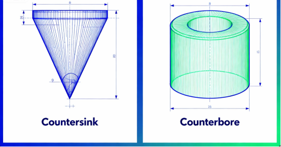
·Countersinks: These are typically conical in shape, created using a tapered drill bit, enabling a screw head to sit flush with or slightly below the board surface.
·Counterbores: These feature a cylindrical shape with a flat bottom, created using an end mill or dedicated counterbore tool, and also serve to recess a screw head below the surface.
The shaft of the screw fits into the drilled hole, ensuring proper alignment and fit between the fastener and the PCB.
These holes are often designed as non-plated through-holes because their primary function is mechanical fastening rather than electrical connection. These features are machined into the PCB workpiece to achieve the desired assembly characteristics.
Key Differences Between Countersinks and Counterbores
To clearly understand their distinctions, here is a comparison table of their main characteristics:
| Characteristic | Countersinks | Counterbores |
|---|---|---|
| Shape | Conical, achieved by creating a taper in the hole | Cylindrical, Flat Bottom |
| Common Angle | 160-180 degrees | Not Applicable |
| Symbol | ‘V’ often precedes diameter callout | Diameter symbol ‘∅’ |
| Primary Use | Reduce overall assembly thickness; designed for screws with a tapered head | Secure specific components/parts; provides a larger hole to accommodate the fastener head |
| Screw Type | Flat Head Screws with a tapered head | Socket Head Cap Screws, Button Head Screws |
The Importance of Countersinks and Counterbores in PCB Design
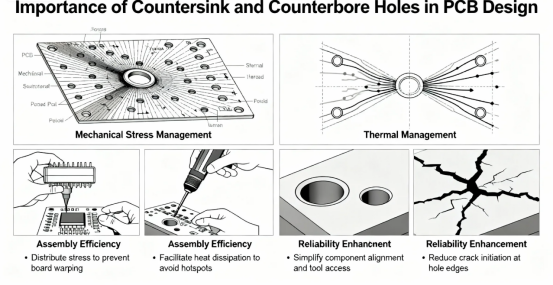
As electronics continue trending towards thinner and lighter form factors, the importance of countersinks and counterbores becomes increasingly evident:
·Space Optimization: By recessing screw heads below the PCB surface, they significantly reduce the overall assembly thickness, which is critical for space-constrained products like smartphones and TWS earbuds.
·Enhanced Stability: They provide more uniform stress distribution, reducing assembly stress and improving the product’s resistance to vibration and shock.
·Prevent Interference: They avoid contact between screw heads and other components or the enclosure, lowering the risk of short circuits.
·Clean Aesthetics: They contribute to a flatter, more orderly internal structure, enhancing the overall perceived quality of the craftsmanship.
The choice between countersink and counterbore holes often depends on the primary concern of the design, such as space-saving, aesthetics, or mounting stability.
Countersink Manufacturing Processes
Generally, the two-step forming method is used for standard PCB applications, while the three-step method is reserved for high-precision requirements.
There are two primary methods for creating countersinks in PCBs:
Two-Step Forming Method
This is a fundamental process involving:
Pre-punching: Creating a pilot hole according to the design specifications.
Press Forming: Using a dedicated die to form the conical countersink structure.
This method involves fewer steps and ensures hole size consistency, but the punch experiences significant stress during the angle forming phase, which can potentially affect precision.
Three-Step Forming Method
For applications demanding higher precision, the three-step method is used:
Pre-punching: Creating the initial hole.
Press Forming: Forming the conical shape.
Final Punching: A final precision punching step to achieve the exact final dimensions.
This method yields better surface finish, higher precision, and more consistent quality, albeit with increased process steps and cost.
Countersink Design Specifications and Practical Advice
Key Dimension Parameters
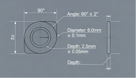
Countersink design involves three main specification parameters:
·Major Diameter (D): The largest diameter of the countersink. The major hole diameter is a key measurement for ensuring accurate fit and is used in conjunction with the angle and depth to achieve proper screw seating.
·Angle (B): The included angle of the cone. Countersink holes are designed with specific angles, and selecting the correct angle is essential for proper screw fit and flush mounting. Common angles for countersink holes include 82°, 90°, and 100°, and these commonly applied angles are chosen to match the screw head for optimal fit and functionality. Different angles may be specified for unique applications, and other angles beyond the standard ones can be used to meet specific manufacturing or aesthetic requirements.
·Depth (H): The depth of the conical section. Hole depth is critical for ensuring the screw head sits flush without damaging the PCB or interfering with components and traces.
Designs must ensure a minimum base thickness (h1) ≥ 0.2 mm to maintain structural integrity.
Design and Manufacturing Considerations
1.Material Considerations: The mechanical properties of different PCB substrate materials (e.g., FR-4, high-frequency materials, metal-core boards) affect countersink quality. Extra caution is needed with brittle or fibrous materials.
2.Placement Planning: Countersinks should be positioned away from sensitive traces and vias. A minimum distance of 0.3mm from the nearest copper feature is recommended. In some designs, a sink such as a heat sink may be attached to the PCB, so countersink holes must be planned to avoid interference with such components.
3.Tool Selection: Creating countersinks requires specialized drill bits or form tools. Tool specifications should be determined based on the required dimensions. If unfamiliar with the process, consult with your PCB fabricator or tooling supplier for assistance.
4.Precision Control: Employ appropriate process controls and inspection equipment, such as optical 3D surface profilers, to perform microscopic topography checks on samples, ensuring countersink quality meets requirements.
Counterbore Countersink Combinations
In certain PCB designs, it may be necessary to combine the features of both counterbore and countersink holes to meet specific assembly requirements. This approach, known as a counterbore countersink, involves creating a flat bottomed hole with a tapered entrance. The result is a hole that can accommodate a screw or bolt inserted from one side of the PCB, allowing the head to sit flush with the opposite surface.
The counterbore portion of the hole provides a flat surface for the screw head to rest against, ensuring stability and even load distribution. The countersink angle at the entrance allows the fastener to sit flush with the surface, maintaining a smooth and unobtrusive finish. This combination is particularly useful in applications where both a secure fit and a flush appearance are required, such as in high-density assemblies or where space constraints are critical.
When designing a counterbore countersink, careful attention must be paid to the dimensions of the hole, including the hole diameter, counterbore diameter, and countersink angle. These parameters must be precisely matched to the fastener’s specifications to ensure proper fit and functionality. Accurate manufacturing processes are essential to achieve the correct finished diameter and to maintain the integrity of the PCB.
By thoughtfully integrating counterbore countersink combinations into PCB design, engineers can achieve both mechanical strength and a clean, professional appearance, ensuring that mounting holes meet the demands of modern electronic assemblies.
Collaborative Design: Countersinks and Other Specialized PCB Hole
In practical PCB design, countersinks often work in concert with other specialized holes:
Integration with Back-Drilling
In high-density board designs, countersinks might coexist with back-drilled vias. Back-drilling is used to remove the unused portion of a plated through-hole via stub to improve signal integrity in high-speed circuits. In such cases, the placement of different hole types must be carefully planned to ensure countersink processing does not compromise the back-drill's function.
Integration with Embedded Passives
In advanced designs, countersinks may need to coexist with embedded passive components (resistors, capacitors). This technology embeds components within the inner layers of the PCB, saving surface space. The design must ensure that the countersink manufacturing process does not damage these embedded elements.
Application Characteristics Across Different Industries
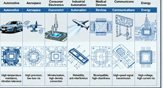
The use of countersinks and counterbores exhibits distinct characteristics across various sectors:
·Automotive Electronics: In systems like radar control units, countersinks must account for stability across wide temperature ranges (-40°C to +125°C or higher), ensuring they don't loosen due to thermal expansion and contraction.
·Medical Equipment: PCBs in medical devices often need to withstand repeated autoclave sterilization cycles (e.g., 134°C steam). Countersink design must ensure structural integrity is maintained through these cycles.
·Consumer Electronics: In products like TWS earbuds and smartwatches, countersinks contribute to extreme miniaturization, enabling more functionality within severely limited space.
·5G Communications: Millimeter-wave modules in 5G base stations demand extremely high PCB flatness. Countersinks ensure tight contact between the housing and PCB, helping to minimize signal reflection at connection points.
Common Issues and Solutions
In certain PCB designs, it may be necessary to combine the features of both counterbore and countersink holes to meet specific assembly requirements. This approach, known as a counterbore countersink, involves creating a flat bottomed hole with a tapered entrance. The result is a hole that can accommodate a screw or bolt inserted from one side of the PCB, allowing the head to sit flush with the opposite surface.
The counterbore portion of the hole provides a flat surface for the screw head to rest against, ensuring stability and even load distribution. The countersink angle at the entrance allows the fastener to sit flush with the surface, maintaining a smooth and unobtrusive finish. This combination is particularly useful in applications where both a secure fit and a flush appearance are required, such as in high-density assemblies or where space constraints are critical.
When designing a counterbore countersink, careful attention must be paid to the dimensions of the hole, including the hole diameter, counterbore diameter, and countersink angle. These parameters must be precisely matched to the fastener’s specifications to ensure proper fit and functionality. Accurate manufacturing processes are essential to achieve the correct finished diameter and to maintain the integrity of the PCB.
By thoughtfully integrating counterbore countersink combinations into PCB design, engineers can achieve both mechanical strength and a clean, professional appearance, ensuring that mounting holes meet the demands of modern electronic assemblies.
Tearing/Burring
·Problem: Burrs or torn material around the edge of the hole during processing.
·Solution: Optimize drill bit speed and feed rate; use sharper tools; consider material stack-up and entry/backup material.
Inconsistent Depth
·Problem: Uneven countersink depth leads to non-uniform screw head heights.
·Solution: Use more stable fixtures and workholding; implement regular tool wear inspection and replacement protocols.
Material Residue (Nub)
·Problem: Incomplete removal of material at the bottom of the hole, leaving a remnant.
·Solution: Optimize the pre-punched pilot hole size to ensure sufficient space before the countersink forming step; verify tool sharpness and process parameters.
Conclusion
Countersinks and counterbores, though small structural elements on a PCB, have a significant and often underappreciated impact on a product's overall performance, reliability, and visual appeal. As electronic products become thinner and their functions more complex, the design and machining processes for these specialized holes will continue to evolve.
Mastering the design essentials of countersinks and counterbores not only helps prevent issues during assembly but also unlocks greater potential for product innovation. In PCB design, sometimes the smallest details make the most significant impact.
If you have further questions about designing specialized holes in PCBs or need solutions for specific application scenarios, we recommend consulting with professional PCB manufacturers for targeted technical support.
FAQs
Q. What is a PCB countersink hole?
A. A countersink hole is a conical hole whose wall forms a specific angle with the PCB surface, typically 82° or 90°. It is used to allow a flat-head screw to sit flush with the PCB surface after installation.
Q. What is a PCB counterbore hole?
A. A counterbore hole is a cylindrical hole with a wider section at the top, enabling a screw head to sit flush with or below the PCB surface. The hole consists of two different diameters: one for the screw head and one for the screw shank.
Q. What is the main difference between countersink and counterbore holes?
A. Countersink holes are conical with different angles, whereas counterbore holes are cylindrical with a flat bottom. Countersink holes are used for flat-head screws, while counterbore holes are for fasteners like hex bolts that require more head space.
Q. When should countersink holes be used in PCB design?
A. Countersink holes should be used when a smooth, inconspicuous surface is required, such as in consumer electronics and compact PCB enclosures.
Q. What information needs to be provided for manufacturing countersink and counterbore holes?
A. For countersink holes, provide the drill bit angle, the diameter of the surface hole, the countersink depth, which board side it is on, and whether the hole axis is plated with copper. For counterbore holes, provide the diameter of the surface hole, the drilling depth, which board side it is on, and whether the hole axis is plated with copper.
Q. Are countersink and counterbore holes more expensive to manufacture?
A. Compared to standard holes, countersink and counterbore holes have higher processing costs due to their more complex manufacturing processes.
Author: Jack Wang

