


The Essential Guide to Understanding FPC Layers in Flexible Circuits
Introduction
Behind the hundreds of daily folds and unfolds of a foldable smartphone screen lies a multilayer FPC less than 0.2 mm thick, enabling the precise connection between the entire display and the mainboard.
Flexible Printed Circuit (FPC), also known as flex PCB, flex print, flexi circuits, and printed circuits, is a key technology enabling the miniaturization and thinning of electronic devices. Flex print and flexi circuits are alternative names for flexible printed circuits, which have a long history as important interconnection technologies for interconnecting electronic devices. From our smartphones and wearables to automotive electronics and medical instruments, FPCs are almost ubiquitous due to their light weight, thin profile, and bendability. FPCs, also referred to as flex PCB and printed circuits, are among the most important interconnection technologies for interconnecting electronic devices.
One of the core factors determining an FPC’s performance and application is its layer stack-up design.
FPC Basics: What are Flexible Printed Circuit Boards?
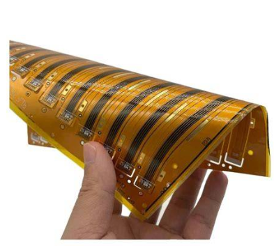
An FPC is a printed circuit board made using flexible insulating substrate materials, offering exceptional flexibility and reliability. Compared to traditional rigid circuit boards, FPCs can be freely bent, wound, and folded, and can even withstand millions of dynamic flex cycles without conductor damage. FPCs require different pcb design considerations than rigid circuit boards, focusing on flexibility, mechanical stress, and signal integrity.
This makes FPCs an ideal solution for meeting the miniaturization and portability demands of electronic products.
The core material of an FPC is typically polyimide film, which offers not only excellent flexibility but also outstanding heat resistance and dimensional stability. In FPC construction, flexible materials are combined with metal foil, such as copper, to form the conductive layers essential for circuit functionality. For different applications, manufacturers may also use other insulating substrates like Polyethylene Terephthalate (PET), aramid fiber ester, and Polyvinyl Chloride (PVC).
Base Material and Structure: The Foundation of FPC Layers
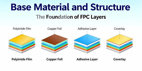
At the heart of every flexible printed circuit board lies its base material and structural design—elements that define the performance, reliability, and versatility of flex circuits across countless electronic devices. The base material, most often a flexible substrate like polyimide (PI) or polyester (PET), serves as the backbone of the flexible printed circuit, providing the mechanical strength and electrical insulation needed for demanding applications.
This flexible substrate, typically a thin polymer film ranging from 12 μm to 125 μm in thickness, is what gives flexible circuit boards their signature bendability and resilience. Onto this base, a conductive layer—usually copper foil—is laminated, forming the essential pathways for electrical connections. The copper foil’s thickness and quality are carefully chosen to balance flexibility with the ability to carry current, a crucial consideration for both simple and complex circuit designs.
Bonding these layers together is the adhesive layer, a critical component that must withstand high temperatures, mechanical stress, and environmental factors. The adhesive not only secures the copper foil to the base material but also plays a vital role in the overall durability and signal integrity of the flexible circuit board. For applications requiring even greater reliability, such as medical devices or industrial sensors, advanced adhesives are selected to resist chemicals, moisture, and repeated flexing.
Modern FPCs often incorporate multiple layers to achieve higher circuit density and more sophisticated electrical connections. Through holes and vias are used to interconnect three or more layers, enabling compact designs that save space and reduce weight—key advantages in mobile phones, consumer electronics, and wearable technology. Sculptured flex circuits, which feature varying conductor thicknesses, are engineered for areas that require both flexibility and durability, while rigid flex circuits combine the best of both worlds: the stability of rigid boards and the adaptability of flexible circuits. This hybrid approach is especially valuable in applications with space constraints or where both static and dynamic connections are needed.
Selecting the right base material and structure is a nuanced process. PCB designers must weigh factors such as high temperature resistance, electromagnetic interference (EMI) shielding, and the need for reliable signal paths. The choice of materials and the design of the FPC layers directly impact manufacturing costs, board thickness, and the ability to withstand high temperatures or harsh environments. For instance, in high-reliability sectors like aerospace or medical electronics, the emphasis is on materials that offer superior thermal properties and chemical resistance.
Despite their many benefits—such as weight reduction, space savings, and the ability to fit into unconventional shapes—flexible printed circuit boards do come with some trade-offs. Manufacturing costs can be higher than those for traditional rigid PCBs, and there may be limitations in terms of maximum signal paths or conductor thickness. However, the advantages often outweigh these challenges, especially in advanced electronic products where flexibility, reliability, and high temperature resistance are paramount.
Whether used in dynamic applications—where the FPC must flex repeatedly, as in foldable displays—or in static roles, providing stable connections in compact assemblies, the base material and structure of FPC layers are fundamental to the success of flexible electronics. By carefully selecting and engineering these components, manufacturers can deliver flexible PCBs that meet the rigorous demands of modern technology, from mobile phones and medical devices to industrial sensors and beyond.
Layer Choices: Key Differences Between Single-Sided, Double-Sided, and Multilayer FPCs
Based on the number of copper layers, FPCs are primarily categorized into three types: Single-Sided, Double-Sided, and Multilayer FPCs. The number of copper layers determines the classification and complexity of FPCs, with more layers enabling more complex circuit designs and functionalities.
A Single-Sided FPC, also known as a single layer FPC, consists of just one copper layer on a flexible substrate. These types differ significantly in structure, performance, and suitable applications.
Single-Sided FPC: A Simple and Cost-Effective Foundation
The single-sided FPC is the most basic form, featuring only one conductive layer etched onto a flexible insulating substrate. It can be further divided into four subtypes: single-access without cover layer, single-access with cover layer, double-access without cover layer, and double-access with cover layer.
The single-access with cover layer type is the most widely used single-sided FPC, commonly found in automotive dashboards and electronic instruments. This type adds a protective cover layer over the conductors, enhancing the circuit’s durability and reliability. In this design, the cover layer is selectively removed in specific regions to expose solder pads—these are the exposed areas of conductive pads where electronic components are soldered, establishing electrical connections.
Double-Sided FPC: Bridging for Higher Wiring Density
Double-sided FPCs have a conductive pattern etched on each side of the insulating base film. These patterns are connected electrically via plated through-holes (PTHs), forming conductive pathways. This design significantly increases wiring density per unit area, accommodating more complex circuit layouts.
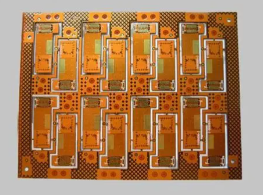
Multilayer FPC: The Solution for Complex Circuits with Multiple Layers
Multilayer FPCs are created by laminating three or more single-sided or double-sided flexible circuit layers together. During this process, an adhesive material is used to bond the layers, and selecting the appropriate adhesive thickness is crucial for achieving the desired flexibility, thermal performance, and electrical properties. Drilling and plating create metallized holes that form electrical connections between the different layers.
Multilayer FPCs offer clear advantages in terms of higher reliability, better thermal conductivity, and more convenient assembly characteristics. They can also help reduce assembly costs by simplifying wiring and integration, eliminating the need for additional fasteners, and streamlining the assembly process.
However, as the layer count increases, multilayer FPCs lose the excellent flexibility of their single and double-sided counterparts. Therefore, most multilayer FPCs are not designed for frequent flexing.
It’s worth noting that unlike rigid PCBs, which typically require an even number of layers for symmetry, FPCs are built by laminating layers one by one and do not require a symmetrical structure. This allows for odd-numbered layer counts like 3, 5, or 7 layers.
Multilayer FPCs can range widely from 3 to 8 layers or more, depending on application requirements. A key design concept in multilayer FPCs is the integration of the substrate and cables, which eliminates the need for connectors. This makes them particularly suitable for confined spaces or lightweight, compact devices.
Applications: Matching Layer Count to Product Requirements
Different FPC layer stack-ups correspond to entirely different application scenarios and product needs.
Single-sided FPCs are lower in cost, suitable for applications with simple circuits and limited budgets. Early telephones used single-access without cover layer single-sided FPCs.
Double-sided FPCs are used in electronics requiring moderate complexity, such as certain instrument cluster components and lighting devices.
Multilayer FPCs can handle the most complex circuit designs and are the preferred choice for modern high-end electronics. They play a critical role in devices like smartphones, satellites, cameras, and hearing aids. Multilayer FPCs are widely used in advanced electronic assemblies and electronic circuits, where integration of multiple components on flexible substrates is essential for performance and miniaturization.
For hybrid solutions or complex applications, rigid flex pcbs combine flexible and rigid layers to provide both flexibility and structural stability, making them ideal for high-density or demanding environments.
FPCs offer significant advantages over traditional solutions, as they can replace wire harnesses in space-constrained or harsh environments, providing a more reliable and compact alternative.
With the rapid development of emerging technologies like 5G, AI, IoT, and electric vehicles, the demand for high-performance, compact electronics continues to grow. This further drives FPC technology toward higher layer counts and greater density.
Key Technical Considerations in FPC Layer Stack-up Design
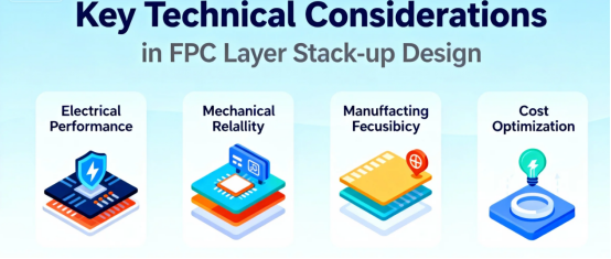
Several key technical points require special attention when determining the FPC layer count.
First is the balance between flexibility and reliability. While multilayer FPCs are more capable functionally, their flexibility diminishes as layers are added. Therefore, in applications requiring frequent bending, some complexity might need to be sacrificed to maintain sufficient flexibility. Flexible circuitry enables innovative designs that can fit into unique spaces and shapes, making it ideal for advanced applications.
Second is cost control. The manufacturing process for multilayer FPCs is more complex, leading to higher costs. FPCs often have a higher cost compared to rigid boards, but they offer unique advantages such as space savings and suitability for specialized applications. Designers must find a balance between performance needs and cost constraints.
Thermal management is another crucial factor. Multilayer FPCs generally offer better thermal conductivity, allowing for more effective dissipation of heat generated by electronic components.
It’s important to note that the layer count of an FPC directly affects its minimum bend radius. An excessively small bend radius can damage the circuit, so the safe bending range must be determined during design based on substrate thickness and layer count. During manufacturing, laser cutting is often used to achieve complex shapes and precise customization of flexible circuits.
Future Outlook: New Trends in FPC Layer Technology
As electronic technology continuously evolves, FPC layer technology is also innovating and advancing.
On one hand, layer counts are increasing to meet the needs of more complex circuit designs. The endless pursuit of miniaturization and functional integration in modern electronics directly pushes FPCs toward higher layer counts.
On the other hand, FPCs with special structures are continually emerging, such as rigid-flex boards. This structure combines the support of rigid boards with the bendability of flexible circuits, offering greater design flexibility.
Material innovation is also a significant trend. New FPC products like low-dielectric-constant LCP-FPCs, high-density multilayer FPCs, waterproof FPCs, and transparent FPCs are constantly appearing, driving progress across the industry. The development of flexible materials is enabling new possibilities in pcb design, especially for applications that require both durability and adaptability.
The rise of wearable devices and IoT equipment has opened new application fields for FPC technology. These devices place higher demands on the thinness, lightness, flexibility, and reliability of FPCs. In particular, FPCs play a crucial role in enabling flexible displays for next-generation consumer electronics and automotive applications, supporting the trend toward more innovative and adaptable device designs.
Summary
Today, inside wearable devices, complex multilayer FPCs are intricately arranged like neural networks, connecting sensors, processors, and batteries. Within the infotainment systems of new energy vehicles, they bend and navigate through limited spaces, ensuring stable transmission for every electrical signal.
Choosing the layer count for an FPC means defining the possibilities for a product’s design. The layer count is not merely a numbers game; it is a precise engineering task of finding the optimal balance between space, performance, cost, and reliability.
FAQs
Q. What are the main types of FPC layers?
A. They are mainly divided into three categories: single-layer FPC, double-layer FPC, and multilayer FPC. Multilayer FPC typically refers to three or more layers. Additionally, there is a special type known as rigid-flex PCB, which combines rigid and flexible layers.
Q. What are the suitable scenarios for single-layer and double-layer FPC?
A. Single-layer FPC is suitable for simple connection scenarios such as sensors and LED light strips, offering low cost and the best flexibility. Double-layer FPC is suitable for moderately complex circuits like mobile phone cables and automotive lighting control, allowing for dual-sided wiring and balancing wiring density with basic flexibility.
Q. What is the core advantage of multilayer FPC?
A. It enables high-density interconnections, allows the setup of independent power and ground layers for electromagnetic shielding, reduces signal crosstalk, supports high-speed signal transmission, and meets the performance requirements of complex circuits in devices such as smartphones and medical equipment.
Q. Does the number of layers in FPC affect flexibility?
A. Yes. The number of layers is inversely related to flexibility. Single-layer FPC offers the best flexibility and can withstand frequent dynamic bending. As the number of layers increases, flexibility decreases. Excessive bending in multilayer FPC can lead to issues such as copper foil cracking and interlayer delamination.
Q. Can FPC be designed with an odd number of layers?
A. Yes. Unlike rigid PCBs, which often require an even number of layers to ensure symmetrical lamination, FPC uses a layer-by-layer adhesive lamination method. This eliminates the need for symmetrical structures, allowing designs with odd numbers of layers, such as three or five layers.
Q. Does an increase in layers affect the cost of FPC?
A. Yes, significantly. More layers require more materials, and multilayer FPC involves complex processes such as laser drilling and precise interlayer alignment. Additionally, manufacturing defects are more likely to occur, leading to lower yield rates. These factors contribute to a substantial increase in manufacturing costs.
Q. Are there special requirements for the bend area design in multilayer FPC?
A. Yes. Vias are prohibited in the bend area and must be placed at least 3 millimeters away from the bend line. Additionally, wiring should be perpendicular to the bending direction to avoid line damage due to stress concentration during bending.
Q. What are the key considerations for selecting the number of FPC layers?
A. Three main factors should be considered comprehensively: first, circuit complexity and signal transmission requirements—multilayer FPC is preferred for complex high-speed circuits; second, the frequency of bending in the application scenario—single-layer or double-layer FPC should be prioritized for frequent bending; third, cost constraints—single-layer FPC is ideal for simple requirements to control costs.
Author: Jack Wang

