Printed Circuit Board Parts Identification Tips for Electronics Enthusiasts
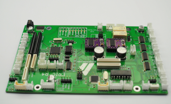
If you enjoy building or repairing electronics, learning how to identify the parts on a printed circuit board (PCB) is very important. Knowing what each component does helps you understand how the device works, find problems, and even create your own projects.
In this article, we will share simple and practical tips for recognizing common PCB parts. You will learn how to read labels, recognize shapes and types, and use basic tools to check components. By the end, you will feel more confident working with PCBs, whether for DIY electronics, repairs, or learning more about circuits.
PCB Basics
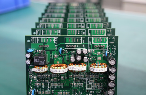
A printed circuit board (PCB) is the foundation of almost every electronic device. It is a flat board that connects electronic components together so they can work as a complete, functioning circuit. Without a PCB, components like resistors, capacitors, and chips would be floating independently, unable to communicate with each other or perform any useful task. PCBs are used in devices of all sizes—from tiny smartwatches to large computers and industrial machines—making them essential to modern electronics.
The Board Material
The board itself is usually made of fiberglass, a strong and lightweight insulating material. Some boards use other insulating materials depending on the device’s needs, such as flexible plastics for bendable circuits or high-temperature materials for industrial electronics. The board provides mechanical strength so the components can be mounted securely. It also acts as an insulator, preventing electrical shorts between different circuits. Some boards have multiple layers of fiberglass and copper, allowing complex circuits to fit into a small area without crossing wires.
Copper Traces
Copper traces are thin lines of copper printed onto the board. They act like tiny wires, carrying electricity from one component to another. The thickness and width of these traces determine how much current they can safely carry. On multi-layer PCBs, some traces may run inside the board, hidden between layers, allowing very complex circuits in a compact design. Proper layout of copper traces is critical because it affects the device’s performance, speed, and reliability.
Pads
Pads are small exposed areas of copper where components are soldered to the board. They provide a secure physical and electrical connection for each component. Pads come in different shapes depending on the component: round pads for through-hole components, square or rectangular pads for surface-mounted devices (SMD), and larger pads for heavy components that need extra support. Good soldering on pads ensures long-term reliability and prevents loose connections, which can cause a device to fail.
Holes or Vias
Holes, also called vias, allow electrical connections to pass from one side of the PCB to the other or between layers in multi-layer boards. Some vias are plated with metal to ensure proper conductivity. Vias let designers route complex circuits without overlapping traces, making multi-layer PCBs possible. In some devices, you may also see mounting holes, which are not conductive but allow screws or fasteners to hold the board in place.
Why Learning PCB Parts Identification Is Important
For electronics enthusiasts, identifying PCB components is the first step to understanding how a circuit works. When you can recognize each part, its function, and how it connects to the board, you can:
· Troubleshoot and repair broken devices more effectively
· Design and build your own electronic projects
· Understand how circuits behave, making learning electronics more intuitive
· Avoid mistakes that could damage the components or the board
By knowing the parts and their roles, electronics stop being mysterious and become something you can explore, experiment with, and enjoy building yourself.
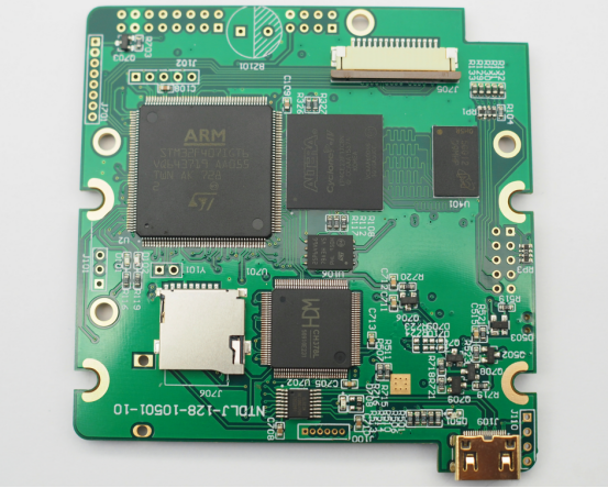
Common PCB Components and Functions
Learning to identify PCB components is essential for anyone interested in electronics. Each component has a specific role and appearance, and understanding them helps you repair, build, or study electronic devices. Knowing the function of each part also makes troubleshooting easier and safer.
Resistors
Resistors are used to control the flow of electric current in a circuit. By limiting current, they protect sensitive components like LEDs and microchips from damage. Resistors also help divide voltage, set timing in circuits, and control signal strength.
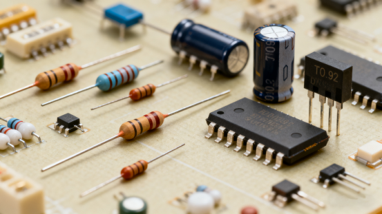
Through-hole resistors are small cylindrical components with colored bands. Each color represents a number according to a standard code, which tells you the resistor’s value. Surface-mounted resistors (SMD) are tiny rectangular blocks with printed numbers indicating their resistance.
Applications: Resistors are everywhere—from dimming an LED in a hobby project to controlling sensor signals in a robot.
Tips and Precautions: Always read the color bands or printed numbers carefully. Using the wrong resistor can change how the circuit works or even burn out other components. Larger resistors can handle more power, while tiny ones are limited to low-current applications.
Capacitors
Capacitors store and release electrical energy. They are used to smooth voltage, filter out noise, and store temporary charge in circuits. Capacitors can stabilize power supplies, improve signal quality, and even help in timing circuits.
Electrolytic capacitors are cylindrical and have a stripe indicating negative polarity. Ceramic capacitors are small, flat, or disk-shaped, usually without polarity. Tantalum capacitors are tiny and marked to show polarity.
Applications: Capacitors appear in power supply filters, audio circuits, signal decoupling, and timing circuits.
Tips and Precautions: Pay close attention to polarity when using electrolytic and tantalum capacitors; connecting them backward can damage the capacitor and the circuit. Check the capacitance and voltage rating before use. Small ceramic capacitors are often overlooked, but they are critical for reducing electrical noise.
Diodes
Diodes allow current to flow in only one direction, acting as a one-way gate for electricity. They are used for protection, converting AC to DC, and controlling signals.
Diodes usually have a black or glass body with a stripe showing the cathode (negative side). SMD diodes are small rectangles with a stripe on one end.
Applications: Diodes are used to protect circuits from reverse voltage, in power supply rectifiers, and in LEDs as indicator lights.
Tips and Precautions: Polarity is crucial. Using a diode backward can prevent the circuit from functioning or damage the diode. You can test diodes using a multimeter in diode mode to ensure correct orientation and functionality.
Transistors
Transistors act as switches or amplifiers. They control current flow and can boost weak signals. Transistors are the building blocks of logic circuits and are essential in almost all electronics.
Common packages include TO-92 (small plastic cylinder), TO-220 (with a heat sink tab), and SMD types. Each transistor has three leads: collector, base, and emitter. Pin layout varies by type and manufacturer, so checking the datasheet is essential.
Applications: Transistors are used to switch LEDs, motors, or other devices on and off. They also amplify audio signals and act as basic computing elements in logic circuits.
Tips and Precautions: Be careful not to overheat transistors during soldering. Always verify pin connections before powering the circuit to avoid damage.
Integrated Circuits (ICs)
ICs are small “brains” that combine multiple transistors, resistors, and capacitors into a single package. They can perform complex tasks like processing signals, storing memory, or controlling devices.
ICs come in DIP, SOIC, QFP, BGA, or SMD packages. Pin 1 is marked with a dot or notch, and the printed code identifies the model. Datasheets provide detailed information about pin configuration, voltage limits, and functionality.
Applications: Microcontrollers, memory chips, sensors, and audio processors all use ICs. They are essential in smartphones, computers, and industrial electronics.
Tips and Precautions: Always check the datasheet before using an IC. Handle ICs carefully to avoid static damage, and make sure pins are correctly aligned when soldering or inserting into a socket.
Other Common Components
Inductors store energy in a magnetic field and are used in power supplies, filters, and RF circuits. They are usually small coils or wrapped components. LEDs emit light when powered and require the correct polarity; the longer lead is usually positive. Switches allow manual control of circuits and are easily recognized by toggles or push-buttons. Connectors provide a way to connect wires, cables, or other boards and vary in size and pin count.
Tips and Precautions: Learn the orientation and markings of these components. Correct placement and connection are crucial for proper circuit function and reliability. Mistakes can lead to malfunction or damage.
Tips for Identifying PCB Parts
Identifying PCB components accurately is essential for anyone building, repairing, or studying electronics. Understanding each part helps prevent mistakes, saves time, and improves the reliability of your work. Here are practical and detailed tips for recognizing PCB parts.
Use Labels and Codes
Many components have printed markings or color codes that indicate their value or type. For example, resistors often have colored bands representing resistance in ohms. Capacitors can have printed numbers or letters indicating capacitance and voltage limits. Integrated circuits (ICs) usually have model numbers printed on their top surface.
Practical Tips:
· For resistors, learn the color code chart or use an online calculator to quickly determine values.
· Check capacitors carefully; some markings are very small or faded. Using a magnifying glass can help.
· Look up IC model numbers in manufacturer datasheets to understand the pinout, voltage range, and functionality.
· Always double-check markings before using a component, especially when replacing old or unknown parts.
Example: You might find a resistor with red, violet, brown, and gold bands. Using the color code, you can determine it is 270 ohms with a 5% tolerance. This ensures you use the correct resistor for your circuit.
Observe Package Types
Components come in different packages, mainly surface-mount (SMD) and through-hole (THT). SMD components are tiny rectangles or squares soldered directly to the PCB surface. THT components have long metal leads that pass through holes in the board.
Practical Tips:
· Learning the visual difference helps you know how to handle the part and which tools to use. Tweezers or a microscope are often needed for SMD parts.
· Knowing the package type helps you understand assembly techniques; THT parts can be replaced manually, while SMD often requires soldering paste or reflow ovens.
· Recognize common SMD codes printed on top of components, such as “103” for a 10kΩ resistor.
Example: A small, flat, black rectangular component with “104” printed on it is a 100nF capacitor in SMD form. Knowing this prevents confusion with similar-looking resistors or inductors.
Measurement and Testing Methods
Using tools like a multimeter or a component tester can verify a part’s type, value, and function. A multimeter can measure resistance, check continuity, or determine diode polarity. Component testers can test transistors, capacitors, and even some ICs without soldering them into a circuit.
Practical Tips:
· Always test old components before reusing them; a resistor may look fine but be out of tolerance.
· Diodes and transistors can be checked for correct forward and reverse behavior.
· Use a multimeter’s continuity function to verify traces or connections if you are unsure.
Example: Before replacing a transistor on a board, you can use a multimeter to check whether the base-emitter junction is functioning correctly. This ensures you don’t install a faulty replacement.
Refer to Schematics and Documentation
PCB schematics, BOM (Bill of Materials) lists, and manufacturer datasheets provide detailed information about every component. They show values, orientation, and function. Cross-referencing these resources makes part identification much easier.
Practical Tips:
· Use the BOM to match part numbers with physical components on the board.
· Refer to schematics to understand the role of each component in the circuit.
· Manufacturer datasheets often include pin configuration diagrams and maximum voltage/current ratings, preventing damage during testing or assembly.
Example: When replacing a microcontroller, consulting the datasheet ensures you connect each pin correctly, avoiding permanent damage to the IC or PCB.
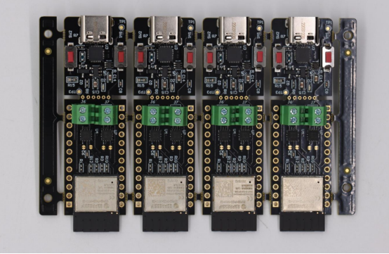
Practical Tools and Resources
When working with PCBs, having the right tools and resources is essential. They make identifying, testing, and understanding components much easier and safer. Here are detailed explanations of the most practical tools and resources for electronics enthusiasts.
Recommended Tools
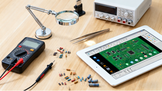
Some basic tools are indispensable for inspecting and identifying PCB parts. A magnifying glass or jeweler’s loupe allows you to see tiny markings on resistors, capacitors, and ICs that are otherwise hard to read. Multimeters measure resistance, voltage, current, and continuity. They can also test diodes and check the proper connection of circuits. Component testers are devices that can measure transistors, capacitors, and some ICs without soldering them into a circuit, saving time and reducing risk of errors.
Detailed Application Example:
If you are repairing an old PCB and suspect a resistor is damaged, use the multimeter to measure its resistance. Compare the result to the color code or printed value. If it is out of tolerance, you know it needs replacement. For SMD LEDs, a multimeter can check polarity and functionality before installation, preventing damage.
Tips:
· Always handle components carefully to avoid bending leads or breaking small parts.
· For very small SMD components, tweezers and a steady hand improve accuracy during inspection.
· Label your tested components to avoid confusion during assembly.
Online Resources
Many online resources provide valuable information for identifying and understanding PCB components. Datasheets include specifications, pin layouts, electrical limits, and recommended applications. Electronics forums and educational websites allow you to ask questions, share images, and learn from other enthusiasts’ experiences.
Detailed Application Example:
Suppose you encounter an IC with an unknown part number. Searching its datasheet online reveals its function, maximum voltage, and pinout. You can then safely integrate it into your project or replace a damaged IC without guessing. Similarly, forums can help confirm the orientation of a tricky SMD component, avoiding potential damage.
Tips:
· Keep a collection of commonly used datasheets for quick reference.
· Use forums to compare your PCB components with images posted by experienced users.
· Cross-reference datasheets with your schematic or BOM to ensure correct installation.
Software Assistance
PCB design software is a powerful tool for understanding components and their placement on a board. Programs like KiCad, Altium Designer, and EasyEDA allow you to view the layout, verify component orientation, and simulate connections. This is especially helpful when dealing with complex or multi-layer PCBs.
Detailed Application Example:
Before soldering an SMD resistor or IC, open the PCB design file to confirm its exact position, orientation, and value. You can also check the corresponding schematic to see how it connects with other parts. This reduces mistakes and ensures correct assembly, saving both time and components.
Tips:
· Use design software to print a reference diagram for real-world inspection.
· Label components digitally and physically to avoid confusion during assembly.
· Even beginners can use free software like KiCad to cross-check part layouts with physical boards.
Common Mistakes and Precautions
Working with PCBs can be challenging, especially for beginners. Even small mistakes can cause a circuit to fail, damage components, or waste time. Knowing the most common errors and how to prevent them is key to successful electronics projects.
Ignoring Polarity or Direction
Many components must be installed in the correct direction to function properly. These include diodes, electrolytic capacitors, LEDs, transistors, and ICs. Installing them backward can prevent the circuit from working, or worse, permanently damage the component or PCB.
Detailed Example:
· If an LED is installed in reverse, it will not light up, but it usually won’t be damaged.
· Installing an electrolytic capacitor backward can cause it to leak, swell, or even explode when powered.
· ICs like microcontrollers or logic chips installed incorrectly may burn out immediately when power is applied.
Practical Precautions:
· Always check the markings: stripes, dots, or longer leads often indicate polarity.
· For ICs, pin 1 is usually marked with a dot or notch. Always align it with the PCB silkscreen.
· Verify component orientation with the schematic or datasheet before soldering.
· When in doubt, use a multimeter to check polarity for diodes and electrolytic capacitors.
Misidentifying Small SMD Components
SMD (surface-mount) components are tiny and often look very similar. Confusing resistors, capacitors, or diodes is common, especially without magnification.
Detailed Example:
· A “104” SMD capacitor may be mistaken for a resistor if you do not read the printed code carefully.
· A small SMD diode may appear identical to a tiny SMD resistor. Installing the wrong part can cause the circuit to malfunction, overheat, or fail entirely.
Practical Precautions:
· Use a magnifying glass, microscope, or phone camera zoom to read markings.
· Organize components by type, value, and polarity before assembly.
· Double-check SMD component codes with datasheets or online reference charts.
· For very tiny parts, consider using tweezers and steady hands to prevent dropping or mixing them up.
Handling Damaged Components or Mixed Models
Sometimes components are old, faulty, or mislabeled. Using them without verification can result in circuit failure. Mixing up similar-looking components, such as two different capacitor values or transistor models, can also cause problems.
Detailed Example:
· Using a 10µF capacitor instead of a 100µF capacitor in a power supply filter may cause voltage instability and damage sensitive components.
· Installing a transistor with the wrong pinout may prevent switching or amplification.
· A resistor with a faded or misread color code may have the wrong resistance, causing circuit instability.
Practical Precautions:
· Test each component with a multimeter or component tester before installation.
· Keep components separated and labeled in trays or boxes according to type and value.
· Record tested components in a notebook or spreadsheet for easy reference.
· When using leftover or salvaged parts, check both the value and condition to avoid hidden failures.
Work Step by Step and Observe Carefully
Rushing through assembly or testing often leads to mistakes. Careful, step-by-step work ensures components are identified, tested, and installed correctly. Observing details and keeping a record of your work reduces errors and improves the quality of your electronics projects.
Detailed Tips:
· Identify each component and verify its value before soldering.
· Check the orientation, polarity, and placement against the PCB silkscreen and schematic.
· Use checklists or simple logs to track which components have been tested and installed.
· Take short breaks to avoid fatigue, which often causes mistakes when dealing with small SMD parts.
· Keep the work area organized to prevent losing tiny components or mixing them up.
Conclusion
Learning to identify PCB components is an important skill for anyone interested in electronics. Understanding each part, its function, and how to recognize it makes working with circuits much easier and safer. This knowledge is the foundation for building, repairing, and experimenting with electronic devices.
Mastering PCB part identification helps in many ways. It allows you to troubleshoot problems quickly, avoid mistakes that could damage components, and confidently assemble your own projects. When you know the parts and their roles, electronics becomes less mysterious and more enjoyable.
By using the tips in this article—reading labels, observing package types, testing with tools, referring to datasheets, and working carefully—you can improve your hands-on skills. Practicing these techniques strengthens your ability to check circuits, fix issues, and understand how devices work.
Remember, electronics is learned step by step. With patience, careful observation, and the right tools, anyone can become confident in identifying PCB parts and handling circuits. Start small, practice regularly, and over time, these skills will make your projects more successful and your learning journey more fun.
If you have more questions or want to learn more about PCBs, feel free to contact PCB MASTER, a professional PCB supplier.
FAQs
How can I tell the difference between similar-looking components on a PCB?
Some components look very similar, like small resistors and capacitors, especially in SMD form. To tell the difference, you can check the printed code or marking on the component. Use a magnifying glass or microscope if the parts are tiny. A multimeter can also help: measure resistance to identify resistors, or capacitance to identify capacitors. Observing the shape, size, and packaging can also give clues—capacitors are often round or rectangular with two leads, while resistors usually have color bands or printed numbers. Organizing your parts and keeping reference sheets nearby makes identification faster and safer.
Why is it important to check components before soldering them on a PCB?
Checking components before soldering prevents mistakes and damage. Even new parts can be faulty, and old or salvaged parts may have changed in value or become damaged. Using a multimeter or component tester, you can verify resistance, capacitance, diode direction, and transistor function. This step also ensures you are using the correct value and polarity. Testing beforehand saves time because you avoid soldering a wrong or faulty component, which can be difficult to remove later. It also increases the reliability of your circuit and reduces the risk of failures.
How can software help me identify and place PCB components correctly?
PCB design software like KiCad, EasyEDA, or Altium Designer shows the layout of every component on the board. You can check position, orientation, and type before soldering. Software also allows you to cross-check the schematic with the physical board, helping you understand how parts connect. For SMD components, software helps confirm exact placement and rotation, reducing mistakes. Some programs even provide 3D views, so you can see the board from all angles. Using software makes assembly faster, safer, and more accurate, especially when working with small or complex PCBs.
