


Printed Circuit Board Edge Connector: Beginner’s Complete Guide
Are you new to electronics and curious about how components connect on a printed circuit board (PCB)? One of the most essential yet often overlooked parts is the PCB edge connector. These connectors let boards interface with other circuits or devices, forming the backbone of countless projects—from simple hobby kits to advanced industrial systems. Understanding their types, design principles, installation methods, and real-world applications can help you confidently tackle your own electronics projects.
Introduction to Printed Circuit Board (PCB) Edge Connectors
What is a PCB Edge Connector?
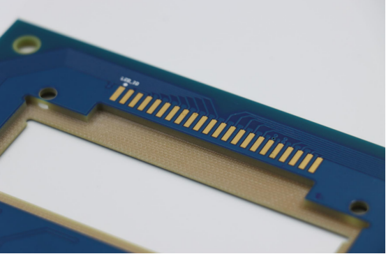
A PCB edge connector is a type of electrical connector that allows a printed circuit board (PCB) to connect directly to another circuit or device through the board’s edge. Unlike traditional connectors, which use wires or sockets, edge connectors rely on exposed metal contacts along the edge of the PCB. These contacts, often called gold fingers, fit into a matching slot on the mating connector, creating a reliable electrical interface.
Key differences from other connectors:
Wire connectors require soldering wires to the board, whereas edge connectors plug directly into a slot.
Socket or pin headers take up more space and often require additional mounting hardware.
Edge connectors are compact, reduce assembly complexity, and support high-density connections.
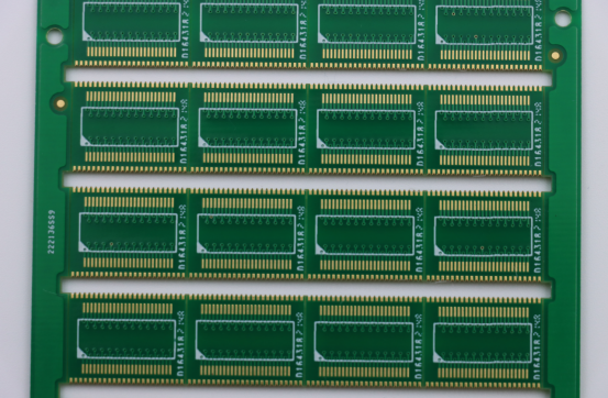
Example: A common example is the edge connector used in computer RAM modules, where the PCB plugs into the motherboard slot. Visualizing this, you can see the exposed metallic edge fitting neatly into a connector slot.
Why PCB Edge Connectors are Important
PCB edge connectors play a crucial role in electronic circuits by providing reliable, high-density connections between boards and devices. They are widely used because they combine simplicity, durability, and ease of replacement.
Key advantages:
Compact design: Saves PCB space compared to traditional connectors.
Reliable connections: Gold-plated contacts resist corrosion and maintain stable electrical performance.
Easy to replace: Boards can be removed or upgraded without resoldering.
Common applications include:
Computers: Memory modules, graphics cards, expansion boards.
Embedded devices: Interface modules in industrial controllers.
Hobby electronics: DIY projects using Arduino or Raspberry Pi shields.
Comparison example: Unlike a typical pin header, which may require multiple wires or connectors, an edge connector can transmit dozens of signals through a single slot, simplifying design and reducing errors.
Who Should Learn About PCB Edge Connectors
Learning about PCB edge connectors is valuable for beginners, electronics hobbyists, and PCB designers who want to design or work with modular electronic systems. Understanding these connectors provides both practical skills and conceptual knowledge for building and maintaining reliable circuits.
Practical benefits for beginners:
Easier assembly and testing of electronic projects.
Ability to upgrade or replace components without soldering.
Understanding how modular electronics communicate at the hardware level.
Example use case for a hobbyist: If you’re creating a DIY game console, knowing how edge connectors work allows you to design swappable circuit boards that plug directly into the main system, similar to retro cartridge-based consoles.
Basic Types of PCB Edge Connectors
Through-Hole vs. Surface-Mount Edge Connectors
PCB edge connectors can be classified by how they are mounted on the board: through-hole and surface-mount. Understanding the differences helps in choosing the right type for your project.
Step-by-step comparison:
1. Through-Hole Edge Connectors
Pins go through holes in the PCB and are soldered on the opposite side.
Pros: Strong mechanical bond, ideal for boards that may face stress or frequent plugging/unplugging.
Cons: Takes up more space, requires drilling holes, slower assembly.
2. Surface-Mount Edge Connectors (SMT)
Contacts are soldered directly onto the surface pads of the PCB.
Pros: Compact design, faster automated assembly, compatible with high-density layouts.
Cons: Less mechanical strength, may need reinforcement for heavy or frequently removed boards.
Example applications:
Through-hole connectors: expansion cards, industrial modules, and retro-style hobby electronics.
Surface-mount connectors: modern RAM modules, small embedded boards, compact consumer devices.
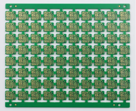
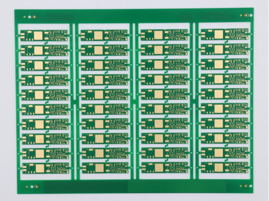
Gold-Finger Edge Connectors
A gold-finger edge connector is a PCB edge connector with gold-plated contacts along the edge.
Why gold plating is used:
Gold plating resists corrosion and oxidation, ensuring that electrical connections remain reliable over the long term. In addition, it provides low contact resistance, a feature that is especially critical for maintaining the integrity of high-speed signals. Together, these properties make gold an ideal choice for connectors where both durability and signal performance are essential.
Typical use:
High-performance PCBs, including memory modules, graphics cards, and server boards, benefit greatly from durable and reliable connections. Additionally, any application that requires frequent plugging and unplugging without compromising the quality of the connection can take advantage of these robust designs, ensuring consistent performance over time.
Example: DDR RAM modules in computers often use gold-finger connectors to maintain reliable performance over thousands of insertion cycles.
Multi-Row vs. Single-Row Connectors
PCB edge connectors also differ in row configuration, which affects pin count and layout.
Differences:
Single-row connectors: One line of contacts, simpler and more compact. Suitable for low-to-moderate signal counts.
Multi-row connectors: Two or more lines of contacts, higher pin density, supports complex circuits or multiple signals in parallel.
Step-by-step guidance for selecting the right type:
1. Determine the number of signals or power lines you need to connect.
2. Consider the available PCB space and board thickness.
3. Check mechanical requirements: will the connector be plugged/unplugged frequently?
4. Match the row type (single vs. multi) to your signal count and spacing requirements.
Example: A small Arduino shield may use a single-row edge connector, while a server backplane uses multi-row connectors to handle dozens of signals efficiently.
Key Components and Design Basics
Connector Anatomy
A PCB edge connector consists of three main parts: pins, contacts, and housing. Understanding these components helps ensure correct design and reliable performance.
Pins: Conductive elements that carry electrical signals or power.
Contacts: The exposed metal sections, often plated with gold or another conductive material, that make contact with the mating connector.
Housing: The insulating structure that holds the pins and contacts in place and provides mechanical stability.
Example visual: A labeled diagram typically shows the pins along the PCB edge, contacts at the connection surface, and the surrounding plastic or insulating housing. This helps beginners quickly identify each component and understand its function.
Standard Sizes and Pitch
Pitch refers to the distance between the centers of adjacent pins or contacts on a PCB edge connector. Correct pitch ensures compatibility with mating connectors and proper signal alignment.
Common standard sizes:
1.27 mm (0.05 inch) – often used in small hobby boards.
2.0 mm (0.079 inch) – used in some compact or custom embedded boards.
2.54 mm (0.1 inch) – standard for many consumer electronics and Arduino shields.
Step-by-step guide to measure a PCB edge connector:
1. Identify two adjacent pins along the connector edge.
2. Measure the center-to-center distance between the pins using a caliper or ruler.
3. Verify the measurement matches the expected pitch of the connector.
4. Repeat for multiple points to ensure uniformity across the connector.
Example: If a connector’s pins measure 2.54 mm apart, it is compatible with a standard 0.1-inch slot on most development boards.
Material and Quality Considerations
The materials used in a PCB edge connector significantly affect its durability, conductivity, and reliability.
Copper: Common base material for contacts; excellent electrical conductivity.
Gold plating: Applied to contact surfaces for corrosion resistance, low contact resistance, and long-term durability.
Plastic housing: Provides insulation and structural support; common types include polycarbonate and PBT.
Comparison of materials:
Copper vs. gold plating: Copper alone conducts well but can corrode; gold-plated contacts last longer and maintain stable signals.
Plastic housing types: Polycarbonate is rigid and heat-resistant, while PBT offers good mechanical flexibility and chemical resistance.
Example: High-performance memory modules often use copper contacts with gold plating and polycarbonate housing to ensure consistent signal integrity even after thousands of insertion cycles.
How to Design a PCB with Edge Connectors
Designing for Footprint Compatibility
To ensure a PCB edge connector fits properly, it’s essential to match the connector dimensions to the PCB footprint. A compatible footprint ensures reliable electrical connections and mechanical stability.
Step-by-step: aligning pads and traces
1. Measure the connector: Identify the length, width, and number of pins.
2. Design PCB pads: Place pads along the PCB edge according to the pin layout and pitch.
3. Check alignment: Verify that pads line up perfectly with the connector contacts.
4. Connect traces: Route traces from each pad to the appropriate circuit components, keeping spacing consistent to avoid shorts.
Example: If you are designing a PCB for a RAM module, ensure the pad layout matches the slot on the motherboard exactly; even a small misalignment can prevent insertion or cause signal failure.
Signal and Power Considerations
Proper PCB design requires attention to both signal integrity and power requirements.
Determining current and voltage limits:
Check the connector’s datasheet for maximum current per pin.
Ensure traces are wide enough to handle the intended current without overheating.
Verify voltage ratings to avoid insulation breakdown or signal degradation.
Tips for minimizing signal interference:
Keep high-speed signal traces short and direct.
Separate power and ground traces from sensitive signals.
Consider adding ground planes or shielding for noise-sensitive circuits.
Example: In a graphics card, improper routing of high-speed memory signals can cause data errors; careful trace layout and grounding reduce this risk.
Common Design Mistakes to Avoid
Avoiding common pitfalls is critical for reliable PCB edge connector design.
Key mistakes:
Overcrowding: Placing too many traces or components near the edge connector can make soldering and insertion difficult.
Wrong pitch: Using incorrect spacing between pads leads to poor connections or short circuits.
Improper trace layout: Long, winding, or intersecting traces can degrade signal quality.
Visual examples:
Bad design: Pads misaligned with connector pins, traces too close together, signals crossing near the edge.
Good design: Pads perfectly aligned, proper spacing, direct traces with minimal interference.
Step-by-step tip: Always double-check the footprint dimensions, measure trace spacing, and simulate the signal path if possible before finalizing the PCB layout.
Installation and Testing
Installing PCB Edge Connectors
Installing a PCB edge connector requires precision to ensure both mechanical stability and electrical reliability. The process differs slightly between through-hole and surface-mount connectors.
Step-by-step guide for through-hole connectors:
1. Insert the connector pins into the corresponding holes on the PCB.
2. Ensure the connector sits flush against the board edge.
3. Heat the soldering iron and apply solder to each pin, forming a solid joint.
4. Inspect each solder joint to confirm there are no cold joints or bridges.
Step-by-step guide for surface-mount connectors (SMT):
1. Apply solder paste to the PCB pads.
2. Place the connector carefully on the pads using tweezers.
3. Reflow solder using a hot air gun or reflow oven until the solder melts and forms reliable connections.
4. Allow the board to cool and inspect all pads for proper adhesion.
Tools needed:
Soldering iron (for through-hole)
Tweezers (for positioning SMT connectors)
Magnifier or microscope (to check small pads and contacts)
Example: Installing a RAM module edge connector on a small hobby PCB often uses SMT techniques to save space and allow precise alignment of the pins.
Testing and Troubleshooting
After installation, testing ensures the edge connector works reliably and prevents electrical failures.
How to check continuity and connectivity:
1. Set a multimeter to continuity mode.
2. Place the probes on corresponding connector pins or traces.
3. Verify that each pin conducts correctly; a beep or continuity reading confirms a proper connection.
Common issues:
Bent pins: Pins misaligned during installation may prevent insertion or cause shorts.
Poor solder joints: Cold or insufficient solder can interrupt the electrical path.
Bridge connections: Solder accidentally connecting adjacent pins causes short circuits.
Example testing method using a multimeter:
Check all pins individually for continuity to their corresponding trace.
Inspect high-speed signal lines with an oscilloscope to ensure minimal signal degradation.
Step-by-step tip: If a pin fails continuity, reheat the solder joint, adjust the pin, and retest. Repeat until all pins show proper connectivity.
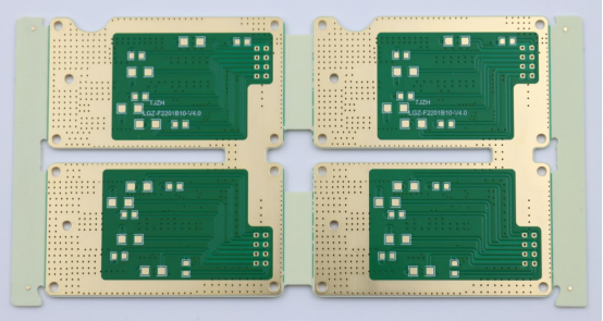
Applications and Real-World Examples
Consumer Electronics
PCB edge connectors are widely used in consumer electronics because they allow modular boards to connect reliably and efficiently.
Examples:
Desktop computers: Memory modules (RAM) plug into motherboard slots using edge connectors.
Game consoles: Expansion cards or cartridge interfaces rely on edge connectors for quick and reliable connections.
Key takeaway: Edge connectors provide a simple, high-density way to connect electronic boards without soldering each time, making devices modular and upgradeable.
DIY and Hobby Projects
Edge connectors are popular in DIY and hobby electronics, allowing makers to design swappable boards or add-on modules.
Example use cases:
Arduino shields: Many shields use edge connectors to stack on top of an Arduino board.
Raspberry Pi hats: Expansion boards use edge connectors to interface directly with GPIO pins.
Step-by-step example: adding an edge connector to a simple PCB project
1. Select an edge connector compatible with your PCB dimensions and pin count.
2. Design or adjust the PCB footprint to match the connector’s pitch and contact layout.
3. Solder the connector using either through-hole or surface-mount techniques.
4. Test connectivity using a multimeter to confirm all pins are properly connected.
5. Attach the board to its corresponding slot or module, ensuring a snug fit.
Tip: Beginners can start with low-pin-count connectors on simple hobby boards to practice alignment and soldering before moving to more complex projects.
Industrial and Embedded Systems
In industrial and embedded systems, edge connectors provide reliable, high-density connections for critical applications.
Typical use cases:
PLC modules: Edge connectors enable modular programmable logic controller boards to plug into a backplane for industrial automation.
Interface boards: Communication and input/output boards often use edge connectors for fast installation and maintenance.
Key advantage: These systems benefit from the durability and repeatable connections that edge connectors provide, reducing downtime and simplifying maintenance.
Conclusion
PCB edge connectors are essential components that allow printed circuit boards to connect reliably with other devices. We’ve covered the main types—including through-hole, surface-mount, gold-finger, single-row, and multi-row connectors—as well as key design basics like footprint compatibility, pitch, pad alignment, and material selection. Proper installation techniques for both through-hole and surface-mount connectors ensure strong, reliable connections, while real-world applications range from consumer electronics and DIY projects to industrial and embedded systems.
For beginners, it’s best to start with simple projects to practice alignment, soldering, and testing. Exploring datasheets, tutorials, and maker communities can help expand your knowledge, and always follow safety precautions when handling PCBs and soldering components.
If you have more questions or want to learn about other PCB topics, you can contact PCBMASTER, an experienced PCB supplier, for professional guidance and answers tailored to your needs.
FAQs
What is the difference between a PCB edge connector and a regular connector?
A PCB edge connector connects directly via the exposed metal contacts (gold fingers) along the edge of a PCB, allowing the board to plug into a mating slot. In contrast, a regular connector typically uses wires, pin headers, or sockets to connect boards or components. Edge connectors are more compact, support high-density connections, and are easier to insert or remove without soldering.
How do I choose the right edge connector for my project?
To choose the right edge connector:
Match the pin count and pitch to your PCB footprint.
Consider signal type and current/voltage requirements.
Decide on connector type (through-hole vs. surface-mount) based on mechanical strength and assembly method.
Factor in row configuration (single-row vs. multi-row) depending on the number of signals to connect.
Can PCB edge connectors be reused or replaced easily?
Yes. Most PCB edge connectors, especially gold-finger types, can be removed and reused if handled carefully. Frequent plugging and unplugging may eventually wear the contacts, but proper alignment and gentle insertion minimize damage.
What is the lifespan of a typical gold-finger edge connector?
A gold-finger edge connector is designed for durability and can typically withstand thousands of insertion/removal cycles. Gold plating prevents corrosion and maintains low contact resistance, making it ideal for high-performance applications.
Are edge connectors compatible across different PCB standards?
Compatibility depends on the pitch, pin count, and footprint of the connector. While some edge connectors follow standard dimensions (like 2.54 mm/0.1 inch), not all are universally compatible. Always verify the PCB design and connector specifications before using across different boards or standards.

