


How Polyimide Heaters Improve Thermal Management in PCBs
A thin, flexible layer of polyimide quietly converts electricity into heat, targeting only the areas of a PCB that require precise temperature control. Carefully designed and integrated, these heaters provide efficient, localized warmth to sensitive circuits, supporting reliable performance without the need for bulky external heating devices. Over time, engineers have refined how these heaters are applied, shaping their layout and power to meet the demands of increasingly complex and high-density boards.
Introduction to Polyimide Heaters in PCBs
What is a Polyimide Heater?
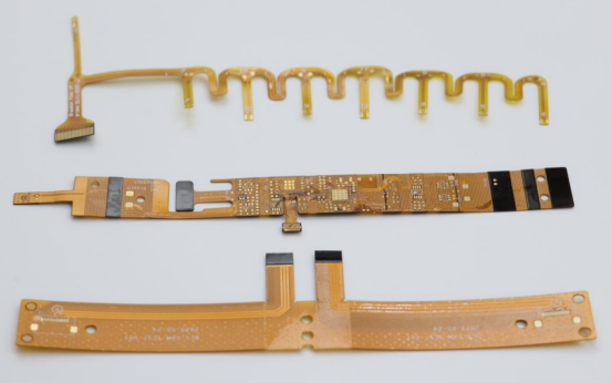
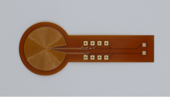
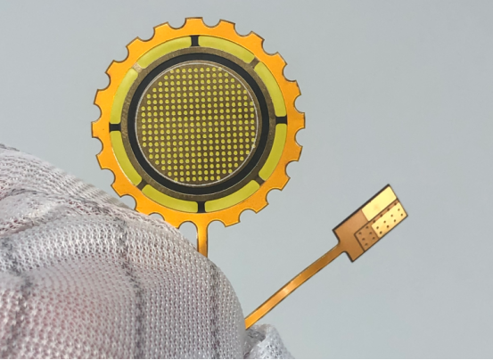
A polyimide heater is a thin, flexible heating element designed to deliver controlled heat to specific areas of a PCB. Its core structure consists of a polyimide film that acts as a durable and heat-resistant substrate, with conductive traces patterned on or embedded within the film. When electricity passes through these traces, they generate heat through the Joule effect, warming the surrounding area efficiently and precisely.
Materials used typically include:
Polyimide film: a high-temperature-resistant polymer that provides mechanical flexibility and electrical insulation.
Conductive traces: often made of copper, silver, or nickel, which are patterned to achieve uniform or targeted heating.
Compared to traditional metal-based heaters, polyimide heaters offer several advantages:
Flexibility: they can conform to irregular surfaces or wrap around components, unlike rigid metal plates.
Precision: heat can be delivered exactly where it is needed, avoiding unnecessary heating of the entire PCB.
Thin profile: they add minimal thickness, making them ideal for compact and high-density boards.
Example: In a multi-layer high-speed PCB, a polyimide heater can be positioned beneath a sensitive BGA chip to maintain consistent temperature during operation, which would be difficult with a bulky metal heater.
Importance of Thermal Management in PCBs
Effective thermal management is critical for modern PCBs. Overheating can lead to:
Reduced performance: excess heat can slow down signal processing or increase electrical resistance.
Component failure: sensitive parts such as microcontrollers, LEDs, or RF modules may degrade or fail prematurely.
Reliability issues: repeated thermal cycling can cause delamination, solder joint cracks, or warping of the PCB.
High-density PCBs face unique thermal challenges, including:
Limited airflow due to tightly packed components.
Localized hotspots caused by power-hungry chips or uneven heat distribution.
Difficulty integrating traditional cooling methods like fans or heat sinks in compact designs.
Integrating polyimide heaters addresses these challenges by:
Providing targeted heating to maintain stable temperatures in thermal-critical areas.
Ensuring uniform temperature distribution to prevent localized hotspots.
Supporting reliable operation in applications where precise temperature control is essential, such as aerospace electronics, medical devices, or industrial control systems.
Step-by-step example:
1. Identify areas of the PCB prone to heat-related issues using thermal simulation.
2. Design a polyimide heater layout that delivers heat specifically to these regions.
3. Integrate the heater during PCB fabrication or attach it to the PCB surface.
4. Apply controlled power to maintain the desired operating temperature.
Working Principle of Polyimide Heaters
How Polyimide Heaters Generate Heat
Polyimide heaters generate heat primarily through the Joule heating effect, also known as resistive heating. When an electric current passes through the conductive traces embedded in the polyimide film, electrical energy is converted into heat. The amount of heat generated depends on the resistance of the traces and the applied voltage.
Typical power density for polyimide heaters ranges from 0.1 to 5 W/cm², depending on the application. This allows temperatures to vary widely, typically from 40°C to over 200°C, providing flexibility for different thermal management needs.
Step-by-step illustration of heat distribution across PCB layers:
1. The polyimide heater is positioned either on the PCB surface or between layers.
2. Electrical current flows through the patterned conductive traces.
3. Heat is generated along these traces and begins to transfer to adjacent PCB layers.
4. Thermal conduction spreads the heat, warming components in a controlled, localized manner.
5. Temperature sensors or control circuits can adjust the current to maintain a steady target temperature.
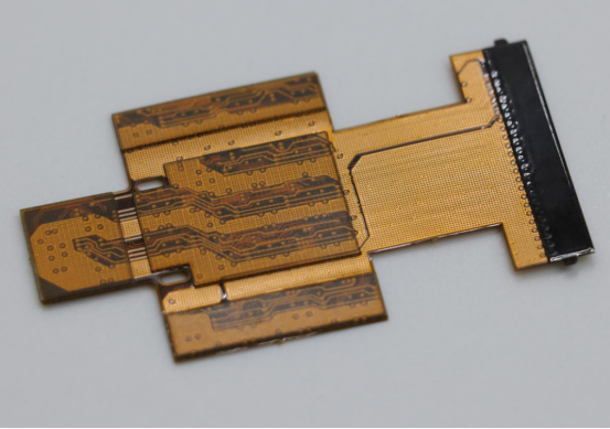
Flexible Design and Integration
Polyimide heaters are highly flexible and can conform to complex surfaces, making them ideal for irregular PCB layouts. This conformal design allows precise heat application even in areas that would be inaccessible to rigid metal heaters.
Layering options in multi-layer PCBs:
Polyimide heaters can be embedded between layers, providing internal heating for thermal-sensitive components.
They can also be surface-mounted, delivering heat to specific zones without affecting surrounding circuits.
Layout and trace design can be customized to ensure even heat distribution across targeted areas.
Comparison with rigid heating solutions:
Polyimide heaters: thin, lightweight, flexible, precise, low-profile.
Rigid heaters (metal plates or ceramic pads): thicker, heavier, less adaptable to irregular surfaces, and may require additional insulation or mounting hardware.
Advantage: Polyimide heaters minimize space consumption and allow for more compact, high-density PCB designs while maintaining reliable thermal control.
Example: A polyimide heater can wrap around a curved sensor module on a PCB, providing uniform warmth that would be impossible with a flat metal plate.
Advantages of Polyimide Heaters for PCB Thermal Management
Uniform Heat Distribution
Polyimide heaters provide uniform heat distribution due to their thin-film design. The conductive traces can be patterned to cover critical areas evenly, reducing the formation of hotspots that might damage sensitive components or cause signal instability.
Example: In a 16-layer high-speed PCB, polyimide heaters can be strategically placed beneath high-power chips. The thin-film heater ensures that all layers and components receive consistent warmth, maintaining stable operating conditions across the board. Without such precise heating, some layers could overheat while others remain cooler, leading to potential reliability issues.
Energy Efficiency and Precision
One of the key advantages of polyimide heaters is their energy efficiency. Because they deliver heat only where it is needed, they consume significantly less power compared to bulky metal or ceramic heaters.
Stepwise control using embedded sensors or controllers:
1. Temperature sensors (such as thermistors or RTDs) detect the real-time temperature of critical PCB areas.
2. The control system adjusts the current supplied to the polyimide heater.
3. The target temperature is maintained precisely without wasting energy on areas that do not require heating.
This precise control allows designers to balance thermal performance and energy consumption efficiently, which is particularly important for portable or high-density electronics.
Reliability and Durability
Polyimide heaters are designed to withstand repeated thermal cycles, making them highly reliable and durable. The flexible polyimide film resists cracking or delamination even under prolonged heating and cooling, which is a common failure mode in traditional rigid heaters.
Lifespan comparison:
Polyimide heaters: Can operate reliably over tens of thousands of thermal cycles with minimal degradation.
Traditional metal or ceramic heaters: May suffer from thermal fatigue, warping, or reduced conductivity over time, especially in high-density or high-speed PCB applications.
By maintaining consistent performance over long periods, polyimide heaters help extend the overall lifespan of the PCB and reduce maintenance or replacement costs.
Applications in PCB Design
High-Density and High-Speed PCBs
Polyimide heaters are especially useful in high-density and high-speed PCBs, where components are tightly packed and thermal management is critical. Typical use cases include:
Aerospace electronics, where reliable operation under extreme temperatures is essential.
Medical devices, such as imaging or diagnostic equipment that require precise temperature control.
Industrial control boards, where prolonged operation generates localized heat hotspots.
Comparison of performance with and without polyimide heaters:
With polyimide heaters: Critical regions maintain stable temperatures, reducing thermal stress, signal degradation, and potential failure.
Without polyimide heaters: Hotspots may develop under high-current components, leading to decreased performance, reliability issues, or shortened PCB lifespan.
Example: In an industrial control PCB, integrating polyimide heaters under power management ICs can prevent localized overheating, ensuring stable operation during continuous use.
Temperature-Sensitive Components
Certain PCB components are highly sensitive to temperature fluctuations, such as BGA chips, LED arrays, and RF modules. Polyimide heaters help maintain a controlled thermal environment for these components.
Step-by-step thermal mitigation strategy:
1. Identify temperature-sensitive components through thermal analysis or simulation.
2. Design polyimide heater traces to target only these critical areas.
3. Integrate heaters either on the PCB surface or between layers.
4. Use sensors and controllers to monitor and adjust heating in real time.
5. Maintain consistent temperature to prevent thermal stress, solder joint cracking, or performance degradation.
Example: In an LED array for a medical device, a polyimide heater ensures uniform brightness and prevents thermal-induced color shifts, which would otherwise occur due to uneven heating.
Prototyping and Production Testing
During PCB prototyping and production testing, maintaining uniform temperature is essential, particularly for soldering and reflow processes. Polyimide heaters help:
Provide consistent heating across the board during reflow, preventing uneven solder joints.
Reduce thermal gradients that can warp or damage the PCB.
Benefits for automated PCB assembly lines:
Enables precise temperature control for high-speed production.
Minimizes defects related to overheating or uneven thermal distribution.
Supports complex multi-layer boards where traditional heaters cannot deliver uniform heat.
Design Considerations for Integrating Polyimide Heaters
Placement Strategies
Proper placement of polyimide heaters is critical to achieving effective thermal management without compromising PCB performance.
Identifying hotspots via simulation:
Thermal simulation tools can map temperature distribution across the PCB under normal operating conditions.
Engineers can locate areas prone to overheating and design heater traces to target those regions specifically.
Example: In a multi-layer high-speed PCB, simulations might reveal that power ICs and memory chips create localized hotspots. Placing polyimide heaters beneath these areas ensures uniform temperature.
Integrating heaters without affecting signal integrity:
Avoid placing heaters too close to high-speed signal lines or RF traces, as excessive heat or conductive layers could interfere with signal quality.
Maintain proper insulation and routing separation to preserve electrical performance.
Power and Control Requirements
The power and control system for a polyimide heater must be designed to match PCB size, target temperature, and thermal dynamics.
Calculating wattage:
Determine the required heat output based on the size of the PCB area to be heated and the temperature difference needed.
Use the formula:
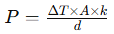
(where ΔT is temperature rise, A is area, k is thermal conductivity, d is thickness) as a starting point.
Options for feedback control:
Thermistors: simple, low-cost temperature sensors for localized control.
RTDs (Resistance Temperature Detectors): offer higher precision and stability over a wider temperature range.
Feedback systems adjust heater power in real time, ensuring consistent temperature without overheating or energy waste.
Step-by-step control example:
1. Sensors measure the temperature at critical points.
2. A controller compares measured values to the target temperature.
3. Current supplied to the polyimide heater is increased or decreased as needed.
4. Temperature stabilizes within the desired range, maintaining component safety and performance.
Material and Manufacturing Constraints
The choice of materials and manufacturing process affects heater performance and PCB integration.
Minimum bend radius for flexible heaters:
Polyimide heaters are flexible but have a minimum bend radius. Bending beyond this limit may damage the conductive traces or the film.
Design layouts to accommodate gentle curves or flat placements when possible.
Compatibility with PCB laminates and surface finishes:
Polyimide heaters must be compatible with the PCB laminate materials (FR-4, polyimide, Rogers, etc.) to ensure proper adhesion and thermal conduction.
Surface finishes like ENIG or HASL should not interfere with heater attachment or operation.
Example: A high-speed PCB using Rogers laminate with ENIG finish can integrate a polyimide heater on the underside, provided the minimum bend radius is respected and adhesion is verified.
Maintenance and Troubleshooting
Common Issues
Even high-quality polyimide heaters can experience issues if improperly handled or over time. The most common problems include:
Heater failure modes:
Open circuits: Breaks in the conductive traces prevent electricity from flowing, stopping heat generation.
Delamination: The polyimide film may separate from the PCB or protective layers, reducing thermal transfer and causing localized cold spots.
Overheating or uneven temperature:
Incorrect placement, insufficient feedback control, or damaged traces can create hotspots or areas that do not reach the target temperature.
Overheating may damage sensitive components or reduce the heater’s lifespan.
Example: A polyimide heater under a BGA chip may develop delamination if the PCB is flexed beyond the minimum bend radius, leading to uneven heating and potential solder joint stress.
Troubleshooting Steps
A systematic approach helps detect and resolve heater issues efficiently:
1. Visual Inspection:
Check for obvious damage, such as tears, bubbles, or delamination of the polyimide film.
Inspect connections and solder joints to ensure continuity.
2. Continuity Testing:
Use a multimeter to measure the resistance of the heater traces.
An open circuit or abnormal resistance indicates a break or damaged trace.
3. Temperature Response Testing:
Power the heater in a controlled setting and monitor temperature with a sensor or infrared camera.
Compare measured temperatures to expected values to identify hotspots or underheated areas.
4. Adjustments or Repairs:
Replace damaged heaters or repair broken traces if possible.
Ensure proper adhesion and placement when reinstalling.
Verify that control systems (thermistors, RTDs, feedback circuits) are functioning correctly.
Example: During PCB prototyping, uneven heating detected via infrared imaging led engineers to adjust heater placement and trace pattern, restoring uniform thermal distribution across the board.
Future Trends in PCB Thermal Management
Advances in Polyimide Heater Technology
Polyimide heater technology continues to evolve, driven by the need for more efficient, precise, and compact thermal management solutions.
Thinner, more efficient films:
Modern polyimide heaters are being manufactured with ultra-thin films that reduce overall PCB thickness while maintaining high thermal output.
Thinner films improve heat transfer efficiency and allow integration into high-density and multi-layer boards without compromising design space.
Example: A next-generation 20-layer high-speed PCB uses a 50-micron polyimide heater film, achieving uniform temperature with less power than older 100-micron designs.
Integration with smart sensors and AI-driven control:
Embedded sensors, such as thermistors or RTDs, provide real-time temperature data.
AI-driven thermal control systems analyze sensor data to dynamically adjust heater power, maintaining precise temperatures while minimizing energy consumption.
Step-by-step operation:
1. Sensors collect temperature readings across critical PCB zones.
2. AI algorithms predict potential hotspots and adjust current to the heater traces.
3. Heater power is modulated in real time, ensuring uniform temperature and preventing overheating.
Emerging Applications
Polyimide heaters are increasingly being applied in flexible electronics, wearables, and IoT devices, where traditional heating solutions are impractical.
Flexible electronics and wearable devices:
Thin, bendable heaters can conform to curved or irregular surfaces, providing warmth or maintaining stable temperatures in devices like smart watches, fitness trackers, or medical patches.
Example: A wearable health monitor uses a polyimide heater to stabilize sensor performance in low-temperature environments without adding bulk.
IoT boards requiring precise temperature management:
Internet of Things (IoT) devices often operate in variable environmental conditions and have compact boards with sensitive components.
Polyimide heaters enable localized heating, ensuring reliable sensor and processor operation without affecting other board areas.
Example: An outdoor IoT sensor network uses embedded polyimide heaters to maintain operating temperature during cold weather, preventing data errors and prolonging device lifespan.
Conclusion
In the world of advanced electronics, precise thermal management can make the difference between peak performance and costly failures. Polyimide heaters offer a flexible, efficient solution for maintaining stable temperatures in high-density and sensitive PCBs. At PCBMASTER, we specialize in designing and manufacturing PCBs that integrate these cutting-edge heaters, helping engineers achieve reliable, high-performance circuits in even the most demanding applications.
FAQs
What are the key differences between polyimide heaters and metal foil heaters?
Polyimide heaters use ultra-thin polyimide film with etched or printed conductive traces, while metal foil heaters rely on thicker metal elements such as stainless steel or nickel foil. Polyimide heaters are more flexible, lighter, and easier to integrate into compact or curved PCB areas. Metal foil heaters, although durable, are bulkier and less suitable for high-density layouts. Polyimide heaters also heat more evenly due to their uniform thin-film structure.
Can polyimide heaters be retrofitted into existing PCB designs?
In many cases, yes. Polyimide heaters can be laminated onto the back side of a PCB or placed between non-critical layers if space allows. Because the film is thin and flexible, it can often fit without significant layout changes. However, retrofitting requires checking clearance, thermal impact on nearby components, and available power budget. For heavily populated boards, redesign may be required to ensure proper placement and reliability.
How do polyimide heaters affect the overall lifespan of a PCB?
When properly integrated, polyimide heaters generally extend PCB lifespan by reducing thermal stress and preventing temperature-related failures. Their stable polymer base resists thermal cycling, and the controlled heating reduces mechanical strain on solder joints and sensitive components. Lifespan issues typically arise only if the heater is overpowered, subjected to excessive bending, or poorly adhered, which can lead to delamination or hotspots.
What is the typical temperature range achievable with polyimide heaters?
Most polyimide heaters operate reliably between 0°C and 200°C, with some specialty versions reaching up to 260°C depending on the conductor material and adhesive system. In PCB applications, the working range is usually set lower—often between 40°C and 120°C—to protect components and maintain long-term stability.
Are polyimide heaters suitable for extreme environments, such as aerospace or automotive applications?
Yes. Polyimide heaters perform well in harsh conditions thanks to their chemical resistance, wide temperature tolerance, and ability to remain flexible in cold environments. Aerospace systems use them for battery warming, sensor stabilization, and avionics temperature control. Automotive electronics benefit from their durability under vibration, cold start conditions, and engine-bay temperature swings. The key is selecting the correct adhesive, insulation, and trace design for the specific environment.

