


Metal Core Printed Circuit Board for Better Thermal Management
In modern electronics, managing heat effectively is critical to ensure reliability and performance. A Metal Core Printed Circuit Board (MCPCB) offers a powerful solution by combining a metal base with advanced PCB layers to efficiently dissipate heat from high-power components. Unlike standard FR-4 boards, MCPCBs are designed for applications where thermal management cannot be compromised, such as LED lighting, power electronics, and automotive systems.
Understanding the structure, materials, thermal performance, manufacturing process, and practical applications of MCPCBs is essential for engineers and designers who want to improve heat dissipation and overall device reliability.
Introduction to Metal Core Printed Circuit Boards (MCPCBs)
What Is a Metal Core PCB?
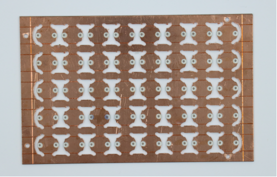
A Metal Core Printed Circuit Board (MCPCB) is a type of PCB that includes a metal layer—typically aluminum or copper—embedded in its structure to help dissipate heat generated by electronic components. Unlike standard FR-4 PCBs, which use an insulating fiberglass substrate, MCPCBs use the metal core as a thermal pathway to remove heat more efficiently.
Key components of a MCPCB include:
Metal core: Conducts heat away from high-power components. Aluminum is lightweight and cost-effective, while copper provides higher thermal conductivity for demanding applications.
Dielectric layer: Electrically isolates the copper circuitry from the metal core while allowing heat transfer.
Copper traces: Form the electrical circuits; thickness can vary to handle higher currents.
Solder mask: Protects the copper traces from oxidation and mechanical damage while maintaining thermal performance.
Comparison with standard FR-4 PCBs:
FR-4 PCBs rely on air and the fiberglass substrate for heat dissipation, which is less effective for high-power components.
MCPCBs are ideal for applications where heat buildup can reduce component lifespan or cause failure
Importance of Thermal Management in Electronics
Electronic devices, especially high-power applications, generate significant heat during operation. Excess heat can lead to:
Reduced component reliability.
Shortened device lifespan.
Potential failures in critical systems.
MCPCBs improve performance by efficiently conducting heat away from hot components through the metal core. By managing heat effectively, they maintain stable operating temperatures and protect sensitive electronics.
Examples of applications:
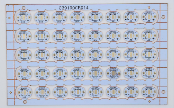
LED lighting: High-power LEDs generate heat that must be dissipated to maintain brightness and longevity.
Power converters: DC-DC converters and inverters require thermal management to prevent overheating of semiconductors.
Automotive electronics: Sensors, motor drivers, and control units often operate under high temperatures and benefit from MCPCB thermal efficiency.
Summary: MCPCBs combine electrical functionality with thermal management, making them essential for modern high-power, high-reliability electronics.
Structure and Materials of MCPCBs
Core Materials
The metal core is the defining feature of MCPCBs, providing efficient heat conduction from high-power components. The most common metals used are aluminum and copper:
Aluminum core: This material is lightweight and cost-effective, offering excellent thermal conductivity that makes it suitable for most LED and general electronics applications. It is ideal for devices where moderate heat dissipation is sufficient.
Copper core: This material offers higher thermal conductivity than aluminum, making it well-suited for high-power or industrial applications. It also provides superior mechanical strength, although this comes with a higher material cost.
Comparison table: Aluminum vs. Copper Core
Feature Aluminum MCPCB Copper MCPCB Thermal conductivity Moderate (~2 W/mK) High (~4 W/mK) Weight
Lightweight
Heavier
Cost
Lower
Higher
Mechanical strength
Good
Excellent
Typical applications
LED lighting, general electronics
Industrial electronics, high-power converters
| Feature | Aluminum MCPCB | Copper MCPCB |
|---|---|---|
| Thermal conductivity | Moderate (~2 W/mK) | High (~4 W/mK) |
Weight | Lightweight | Heavier |
Cost | Lower | Higher |
Mechanical strength | Good | Excellent |
Typical applications | LED lighting, general electronics | Industrial electronics, high-power converters |
Dielectric Layer
The dielectric layer separates the metal core from the copper circuit, providing electrical insulation while allowing heat to transfer efficiently.
Its primary role is to electrically isolate copper traces from the metal core, preventing short circuits, while also conducting heat from components down to the metal core.
Common materials used for the dielectric layer include thermally conductive epoxy or polymer composites, with typical thermal conductivity ranging from 1.0 W/mK to 3.0 W/mK depending on the material grade.
Design tip: A thinner dielectric improves heat transfer but must maintain sufficient insulation to prevent electrical failure.
Copper Circuit Layer
The copper layer forms the electrical pathways for the PCB and plays a role in heat spreading.
Thickness options:
Standard 1 oz (35 µm) to 4 oz (140 µm) copper, depending on current requirements.
Thicker copper improves current-carrying capacity and reduces resistive losses.
Design considerations:
High-current traces should be wider and possibly doubled up to handle heat without excessive voltage drop.
Thermal vias may connect copper traces to the metal core for enhanced heat dissipation.
Solder Mask and Surface Finishes
The solder mask and surface finishes protect the copper circuit while influencing thermal and electrical performance.
Protection: Prevents oxidation, corrosion, and mechanical damage during assembly and operation.
Common finishes:
HASL (Hot Air Solder Leveling): Easy to solder, moderate thermal impact.
ENIG (Electroless Nickel Immersion Gold): Excellent surface flatness, good thermal performance, ideal for fine-pitch components.
OSP (Organic Solderability Preservatives): Cost-effective, preserves solderability for moderate-term storage.
Impact on thermal/electrical performance: Finishes with better thermal conductivity can slightly improve heat transfer from traces to components, while high-quality finishes ensure reliable solder joints.
Thermal Performance and Heat Dissipation
How MCPCBs Dissipate Heat
Metal Core PCBs (MCPCBs) manage heat by creating a direct thermal path from components to the ambient environment. The heat flow typically follows this sequence:
1. Component heat generation: High-power components such as LEDs, power transistors, or voltage regulators produce heat during operation.
2. Copper circuit layer: Heat spreads across the copper traces connected to the component pads.
3. Dielectric layer: Conducts heat down to the metal core while electrically insulating the copper traces from the core.
4. Metal core: Acts as a heat spreader and transfers thermal energy to a heat sink or directly to ambient air.
Role of thermal vias and planes:
Thermal vias are plated holes that connect the copper traces on the top layers to the metal core. They enhance vertical heat transfer and help reduce hot spots, ensuring a more uniform board temperature. In addition, copper planes on the surface assist in spreading heat horizontally, complementing the thermal performance of the metal core.
Example: In a high-power LED board, thermal vias beneath LEDs can reduce junction temperature by 10–15°C compared to boards without vias.
Thermal Resistance and Conductivity Metrics
Thermal resistance (Rθ, °C/W) measures how well a PCB transfers heat away from components. Lower thermal resistance indicates better heat dissipation.
Calculation: Rθ = (Temperature difference between component junction and ambient) ÷ Power dissipated.
Importance: A lower Rθ prevents overheating, extends component life, and maintains consistent performance.
Example: Comparing an MCPCB with a standard FR-4 board for a 10W LED:
FR-4 PCB: Thermal resistance ~20 °C/W → LED junction temperature rises rapidly, shortening lifespan.
Aluminum MCPCB: Thermal resistance ~5 °C/W → Heat is efficiently conducted to the metal core, keeping the LED cooler and extending its operational life.
Design Strategies for Optimal Thermal Management
Effective MCPCB design enhances heat dissipation and overall device reliability:
Placement of high-power components: Keep high-heat-generating components close to the metal core or heat sinks. Avoid clustering heat sources in one area.
Copper trace width and metal core thickness: Wider copper traces reduce resistance and help spread heat. Thicker metal cores improve overall heat conduction but may add weight or cost.
Thermal vias: Optimize number, diameter, and location to connect top copper layers to the metal core.
Simulation tools: Use thermal simulation software (e.g., Ansys Icepak, SolidWorks Flow Simulation) to predict hot spots and evaluate different designs before fabrication.
Example: On a DC-DC converter board, placing MOSFETs over a thicker aluminum core with multiple thermal vias reduces junction temperature by 20%, preventing thermal shutdown during peak load.
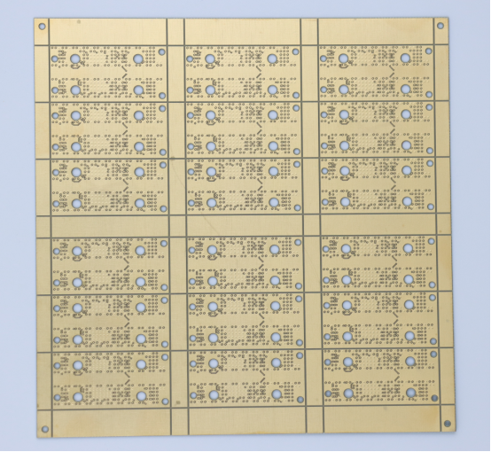
Manufacturing Process of MCPCBs
Fabrication Steps
The fabrication of a Metal Core PCB (MCPCB) involves several specialized steps to integrate the metal base with the electrical circuitry:
Core preparation: The metal core, typically made of aluminum or copper, is first cut and cleaned to remove any impurities. Stress relief may then be applied to prevent warping during subsequent lamination and drilling processes.
Dielectric lamination: A thermally conductive dielectric layer is laminated onto the metal core, providing electrical insulation while allowing efficient heat transfer. The thickness and choice of material for this layer directly impact both the thermal performance and mechanical stability of the board.
Copper etching: Copper foils are laminated onto the dielectric layer, and unwanted copper is then removed through etching to form the desired electrical traces.
Drilling and plating: Holes are drilled into the board to accommodate component leads or thermal vias. These holes are then plated to connect the copper layers and provide efficient pathways for heat conduction.
Special considerations for metal cores: Cutting and drilling processes must take into account the hardness of the metal core. Excessive heat during drilling can lead to warping or delamination of the board. Using proper fixturing and tooling helps minimize mechanical stress and ensures the integrity of the board during fabrication.
Assembly Considerations
MCPCBs present unique challenges during component assembly due to their high thermal mass:
Component placement: Surface-mount technology (SMT) and through-hole components are mounted in the same way as on standard PCBs. However, the high thermal conductivity of the metal core can influence solder adhesion and the heating process during assembly.
Soldering challenges: Metal cores dissipate heat rapidly, which may necessitate adjustments to reflow profiles to ensure the solder paste melts properly. Uneven heating during this process can result in cold joints or insufficient solder flow.
Reflow profile adjustments: Slower ramp-up rates and longer soak stages may be necessary to allow the board to reach uniform temperatures. Monitoring the process with thermal profiling equipment helps ensure proper soldering while preventing damage to components.
Quality Control and Testing
Ensuring MCPCB reliability requires thorough inspection and testing at multiple stages:
Thermal performance testing: Verify heat dissipation under operational loads.
Example: Thermal imaging cameras detect hotspots on high-power LED boards to confirm uniform heat spreading.
Electrical checks: Continuity and isolation tests ensure no short circuits or open traces exist.
Mechanical inspection: Verify drilling accuracy, plating integrity, and absence of warping or delamination.
Outcome: Strict quality control ensures MCPCBs perform reliably in high-power applications, meeting both thermal and electrical specifications.
Applications of MCPCBs
LED Lighting
High-power LEDs generate significant heat that must be efficiently dissipated to maintain performance and longevity. MCPCBs are ideal for these applications because their metal cores conduct heat away from the LED junctions, preventing overheating.
Examples of LED applications:
Streetlights: Large arrays of LEDs produce high thermal loads that MCPCBs manage effectively.
Automotive headlamps: Thermal management ensures consistent brightness and prevents premature failure.
Grow lights: Maintaining stable operating temperatures improves LED lifespan and energy efficiency.
Power Electronics
Power electronic devices, such as DC-DC converters, power amplifiers, and motor drivers, handle high currents and voltages, producing substantial heat. MCPCBs improve reliability by reducing thermal stress and maintaining stable temperatures.
Benefits of using MCPCBs in power electronics:
Improved heat dissipation, preventing overheating of sensitive components like MOSFETs and ICs.
Enhanced efficiency, as cooler components operate closer to their optimal performance.
Reduced failure rates, lowering maintenance and downtime.
Example: A high-current motor driver on a standard FR-4 PCB may reach junction temperatures exceeding safe limits, while an MCPCB maintains safe operating temperatures under the same load.
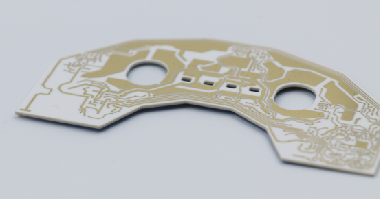
Automotive and Industrial Electronics
MCPCBs are widely used in automotive and industrial systems where components are exposed to high ambient temperatures or continuous operation.
Applications:
Sensors and actuators in vehicles and industrial machinery.
High-power industrial drivers and control boards.
Example comparison:
Standard PCB: May experience hotspots, causing component derating or failure in a high-temperature automotive engine bay.
MCPCB: Metal core efficiently spreads and dissipates heat, ensuring components remain within safe temperature ranges, improving reliability and lifespan.
Key takeaway: MCPCBs are essential for any high-power or high-temperature electronics where traditional FR-4 PCBs cannot provide adequate thermal management.
Design and Cost Considerations
Trade-Offs Between Thermal Performance and Cost
Selecting the right metal core involves balancing thermal efficiency with material cost:
Aluminum vs. copper core:
Aluminum: Lightweight, cost-effective, sufficient for most LED and moderate-power applications.
Copper: Higher thermal conductivity, ideal for industrial or high-current applications, but more expensive and heavier.
Core thickness: Thicker metal cores improve heat dissipation by increasing thermal mass and spreading heat more effectively. However, thicker cores also increase material costs and may complicate handling and assembly.
Example: For a high-power LED streetlight, a 1.5 mm aluminum core may provide sufficient thermal management at lower cost, whereas a copper core would offer superior heat conduction but significantly increase production expense.
Design Guidelines for Manufacturability
Proper design ensures MCPCBs are both thermally efficient and easy to assemble:
Copper thickness: Minimum 1 oz is standard; higher current applications may require 2–4 oz.
Via size and placement: Thermal vias should connect high-heat areas to the metal core without compromising electrical isolation.
Component spacing: Adequate spacing reduces thermal interference and simplifies soldering.
Impact of core selection:
Copper cores dissipate heat faster but may require adjusted reflow profiles.
Aluminum cores are easier to handle but may need additional thermal vias for optimal performance.
Step-by-step tip: Start with core selection, determine copper thickness for current requirements, then layout components with thermal vias and spacing optimized for both heat management and assembly ease.
ROI and Longevity
Investing in an MCPCB with proper thermal management provides measurable returns over the product’s lifecycle:
Reduced component failures: Lower operating temperatures extend lifespan of LEDs, MOSFETs, ICs, and other high-power components.
Energy efficiency: Cooler components often operate more efficiently, reducing power loss and potential heat-related downtime.
Cost-benefit analysis: The initial cost of metal core PCBs may be higher than that of standard FR-4 boards. However, cost savings can be realized through reduced rework, fewer warranty claims, and longer overall product life.
Example: A DC-DC converter using a copper-core MCPCB may cost 30% more initially but reduces failure-related maintenance by 50%, yielding long-term savings and improved reliability.
Future Trends in MCPCBs
Advanced Materials
Next-generation MCPCBs are exploring high-thermal-conductivity ceramics and hybrid metal cores to further improve heat dissipation.
Ceramic cores: Provide superior thermal conductivity, electrical insulation, and stability under high temperatures. Ideal for high-power LED and industrial electronics.
Hybrid metal cores: Combine aluminum or copper with ceramic layers to balance thermal performance, weight, and cost.
Example: A hybrid aluminum-ceramic MCPCB in an industrial LED driver can maintain lower junction temperatures than traditional aluminum-core boards, enhancing reliability and efficiency.
Integration with Smart Electronics
MCPCBs are increasingly used in IoT devices and smart systems, where adaptive thermal management and on-board sensors enhance performance.
Adaptive thermal management: Sensors detect hotspots and adjust device operation to prevent overheating.
On-board monitoring: Enables predictive maintenance and improves system reliability.
Example: Smart LED streetlights with embedded temperature sensors on MCPCBs can regulate brightness and prevent overheating during peak load periods.
Miniaturization and High-Power Density Applications
As electronics become smaller and more powerful, MCPCBs are evolving to support compact devices with high power density.
BGA (Ball Grid Array) and CSP (Chip Scale Package) components: Require precise thermal management due to high heat output in small areas.
High-current MCPCBs: Enable compact power electronics without compromising heat dissipation.
Example: Miniaturized motor drivers in drones use high-power-density MCPCBs to deliver maximum performance while keeping components cool within a limited space.
Key takeaway: Future MCPCB designs will focus on advanced materials, smart integration, and miniaturization, enabling higher performance, longer lifespan, and smarter thermal management in a variety of electronic applications.
Conclusion
Efficient thermal management is critical for high-power electronics, and Metal Core PCBs (MCPCBs) provide a reliable solution. From LED lighting to automotive and industrial applications, MCPCBs ensure components operate safely, efficiently, and with extended lifespan.
Partnering with experienced manufacturers like PCBMASTER guarantees high-quality MCPCBs, precise fabrication, and optimal thermal performance, helping engineers and designers bring their high-power projects to life with confidence.
FAQs
1. What makes a metal core PCB better than a standard FR-4 PCB for thermal management?
Metal core PCBs (MCPCBs) feature a metal layer, typically aluminum or copper, beneath the dielectric layer, which efficiently conducts heat away from high-power components.
In contrast, standard FR-4 PCBs use a fiberglass-reinforced epoxy substrate with low thermal conductivity, causing heat to accumulate near components.
MCPCBs help reduce component junction temperatures, prevent thermal hotspots, and improve reliability in high-power applications such as LEDs, power electronics, and automotive systems.
For example, a high-power LED on a standard FR-4 board may reach a junction temperature of 85–90°C, whereas the same LED on an aluminum MCPCB could operate around 60–65°C under the same load.
2. How do aluminum and copper MCPCBs differ in performance and cost?
Feature Aluminum MCPCB Copper MCPCB Thermal conductivity Moderate (~2 W/mK) High (~4 W/mK) Weight
Lightweight
Heavier
Cost
Lower
Higher
Mechanical strength
Good
Excellent
Typical applications
LED lighting, general electronics
Industrial electronics, high-power converters
| Feature | Aluminum MCPCB | Copper MCPCB |
|---|---|---|
| Thermal conductivity | Moderate (~2 W/mK) | High (~4 W/mK) |
Weight | Lightweight | Heavier |
Cost | Lower | Higher |
Mechanical strength | Good | Excellent |
Typical applications | LED lighting, general electronics | Industrial electronics, high-power converters |
Performance: Copper cores provide faster heat dissipation and are better for high-power or high-current applications, whereas aluminum cores are adequate for moderate-power electronics.
Cost: Copper MCPCBs are more expensive due to material cost and handling complexity.
Example: Using copper MCPCB in a 200W LED driver ensures lower junction temperature and longer lifespan, but aluminum MCPCB may suffice for a 50W LED module at a lower cost.
3. Can MCPCBs be used for both LED and automotive applications?
Yes. MCPCBs are highly versatile and suitable for any high-power or high-temperature application.
LED applications: Provide efficient heat dissipation to maintain brightness and longevity.
Automotive applications: Handle high ambient temperatures and continuous operation in sensors, motor drivers, and headlamp modules.
Example: A single MCPCB type may be designed with an aluminum core for streetlights and adapted with a thicker or copper core for engine bay electronics in cars.
4. What design factors most affect the heat dissipation of a metal core PCB?
Key factors include:
Metal core material: Aluminum vs. copper affects thermal conductivity.
Core thickness: Thicker cores spread heat more effectively.
Copper trace width: Wider traces reduce resistance and spread heat.
Dielectric layer properties: Material thermal conductivity and thickness affect heat transfer to the core.
Thermal vias: Enable vertical heat transfer from surface-mounted components to the metal core.
Component placement: High-power components should be positioned near heat sinks or evenly spaced to avoid hotspots.
Surface finish: ENIG or HASL can slightly impact heat transfer and solderability.
5. How do thermal vias enhance the performance of MCPCBs?
Thermal vias are plated holes connecting copper traces on the PCB surface to the metal core. They provide direct pathways for heat from surface-mounted components down to the metal layer.
Benefits include:
Reducing component junction temperature.
Minimizing hotspots on the board.
Allowing higher power density in compact designs.
Example: A high-power LED array with 10–20 thermal vias per LED sees a 10–15°C reduction in junction temperature compared to a board without thermal vias.

