


Metal-Based PCBs with Thermoelectric Separation for Heat Dissipation
As power demands continue to rise in industries like LED lighting and automotive electronics, the need for efficient heat dissipation has never been more critical. Traditional thermal management solutions often fall short, particularly when it comes to handling high-power applications. That’s where metal-based PCBs with thermoelectric separation come into play, offering a revolutionary approach to heat transfer. By bypassing common thermal bottlenecks, these advanced PCBs deliver superior performance, extending the lifespan and enhancing the reliability of electronic components. This article delves into the principles and advantages of this innovative technology, exploring how it’s changing the landscape of heat management in high-power electronics.
Thermoelectric Separation Technology in Metal-Core PCBs
Principle of the Technology
Through an etching process, an independent raised structure is formed on the substrate:
1. The conductive pads handle the circuit connections.
2. The thermal pads directly contact the metal substrate for efficient heat dissipation. This structure allows the heat source of the LED chip to bypass the insulating layer, improving thermal conductivity.
When it comes to metal-core PCBs, most people immediately think of aluminum-based boards, which are commonly used in low-power LED applications. Generally, metal-core PCB materials fall into three main categories: aluminum-based, copper-based, and iron-based PCBs. As high-power electronics and high-frequency PCBs continue to evolve, the demands for better heat dissipation and smaller form factors are increasing. Traditional aluminum boards can no longer meet these demands, leading to the increasing use of copper-based PCBs, particularly in high-power products. Many of these applications require more advanced processing techniques for copper PCBs.
So, what exactly is a copper PCB, and what makes it so advantageous? Let's dive into the details.
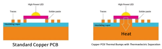
Consider the typical aluminum or copper PCB. Heat dissipation relies on an insulating thermal layer (shown in purple in the image), which is relatively easy to process. However, once the heat passes through the insulating layer, the thermal conductivity decreases, making it suitable only for low-power LED lights. For automotive LED modules or high-frequency PCBs, where heat dissipation is a significant challenge, both aluminum and conventional copper PCBs no longer suffice. In these scenarios, thermoelectric separation copper PCBs are often the solution.
What is a Thermoelectric Separation Copper PCB?
In these copper PCBs, the circuit layer and thermal layer are placed on different layers of the PCB. The thermal layer directly contacts the heat dissipation part of the LED chip, achieving optimal heat dissipation with near-zero thermal resistance.
Advantages of Thermoelectric Separation Copper PCBs:
Copper itself has excellent thermal conductivity, ensuring efficient heat transfer.
The thermoelectric separation structure enables direct contact with the LED chip, minimizing light degradation and significantly extending the LED’s lifespan.
Higher density allows for smaller sizes while maintaining the same power output.
Ideal for single high-power LED chips, especially COB (Chip on Board) packages, enhancing the overall lighting effect.
Customizable designs, such as copper bumps, copper recesses, or parallel heat dissipation structures, are possible depending on the specific requirements of the lighting fixture.
Core Structural Comparison:
1. Standard Aluminum/Copper PCBs
Layer Structure:
Conductive layer (copper) → Insulating layer (thermal conductivity: 1-3 W/mK) → Metal base (aluminum/copper)
Thermal Bottleneck:
The insulating layer’s low thermal conductivity becomes the main barrier to heat transfer, making these boards suitable only for low-power applications (<50W).
2. Thermoelectric Separation Copper PCBs
Optimized Structure:
Conductive layer (copper) + Etched openings in the insulating layer + Copper heat dissipation bumps + High thermal conductivity copper base
Core Advantage:
Copper heat dissipation bumps (thermal conductivity: 380 W/mK) bypass the insulating layer, reducing thermal resistance by over 80%, and making it suitable for high-power applications (50-500W+).
Key Comparisons:
| Comparison Dimension | Standard Aluminum/Copper PCBs | Thermoelectric Separation Copper PCBs |
| Layer Structure | Copper conductive layer → Insulating layer → Metal base (aluminum/copper) | Copper conductive layer → Etched openings → Copper heat dissipation bumps → High-conductivity copper base |
| Thermal Conductivity | Insulating layer typically has a thermal conductivity of 1-3 W/mK, with custom options ranging from 4-15 W/mK. Heat must pass through the insulating layer. | Copper heat dissipation bumps have a thermal conductivity of 380 W/mK, directly bypassing the insulating layer for efficient heat transfer. |
| Heat Dissipation Features | Insulating layer leads to inefficient heat transfer, causing heat buildup and higher thermal resistance. | Thermal resistance is reduced by over 80%, with a direct and short heat transfer path, allowing for faster heat dissipation. |
| Applicable Power Range | Suitable for low-power applications (<50W) | Suitable for high-power applications (50-500W+) |
What Does the "Thermal Conductivity" of Metal-Core PCBs Mean?
The thermal conductivity of metal-core PCBs (such as aluminum, copper, and iron-based PCBs) is a key physical property that measures the material's ability to conduct heat, with units of W/(m·K) (watts per meter per kelvin). The higher the thermal conductivity, the more efficiently heat is transferred from the heat-generating components to the metal substrate and heat dissipation end, which allows for faster cooling of the components and improves product stability and longevity.
In PCB applications, thermal conductivity primarily refers to the overall heat transfer performance of the substrate. This includes the heat transfer capabilities of the insulating thermal layer and depends on the heat dissipation properties of the metal substrate. Both factors together determine the overall thermal efficiency of the metal-core PCB.
Core Concept: It measures the ability of heat to transfer from the circuit layer (copper foil, where heat is generated) through the insulating layer to the metal base (such as aluminum, used for heat dissipation). The unit is W/(m·K), which stands for watts per meter per kelvin.
Key Understanding: The metal base (e.g., aluminum) has a high thermal conductivity (around 200 W/(m·K)), so it is not a bottleneck for heat dissipation. The insulating layer in the middle (typically made of epoxy resin or polymers filled with high-conductivity ceramic powders) is the main source of thermal resistance. Its thermal conductivity typically ranges from 1.0 W/(m·K) to 15 W/(m·K), much lower than that of the metal.
Therefore, when we talk about the "thermal conductivity" of a metal-core PCB, we are almost always referring to the conductivity of the insulating layer. A higher value indicates a lower thermal resistance in the insulating layer, allowing heat to transfer more easily from the heat-generating components to the metal base for dissipation.
What Determines the Thermal Conductivity of Metal-Core PCBs?
The thermal conductivity of the insulating layer in metal-core PCBs is primarily determined by the following factors:
Resin Material: The base material of the insulating layer, such as epoxy resin, polyimide, or silicone. These materials have poor thermal conductivity (~0.2 W/(m·K)).
Thermal Fillers: The key to improving thermal conductivity. By adding high-conductivity ceramic powders to the resin base, thermal paths are formed. Common fillers include:
- Aluminum Oxide (Al₂O₃): The most commonly used, cost-effective filler, which can improve the thermal conductivity to 1.0-2.5 W/(m·K).
- Aluminum Nitride (AlN): Excellent thermal properties (theoretical values are very high), with insulating layer thermal conductivity exceeding 5 W/(m·K), but it is expensive and requires more complex processing.
- Boron Nitride (BN): A material with a sheet-like structure that forms an efficient thermal network in the plane direction, providing anisotropic heat conductivity.
- Beryllium Oxide (BeO): Has exceptional properties but is toxic, so it is rarely used nowadays.
Filler Ratio and Process: The proportion, particle size, shape distribution, and the bonding process between the filler and resin directly affect the formation of the thermal network. A higher filler ratio leads to better thermal conductivity, but it can degrade the mechanical properties and workability of the insulating layer.
Interface and Structure: The bonding interface between the insulating layer and the copper foil, as well as the metal substrate, also impacts overall thermal conductivity. If the interface is not tightly bonded or has air gaps, thermal transfer efficiency is reduced.
In Summary: The thermal conductivity of the insulating layer is the result of the combination of low-conductivity resin base, high-conductivity fillers, and optimized mixing and curing processes.
Voltage Rating of Metal-Core PCBs
The voltage rating of metal-core PCBs (including aluminum, copper, and iron-based boards) is primarily determined by the material, thickness, and manufacturing process of the insulating thermal layer. The voltage rating varies depending on the application, with the industry-standard ranges outlined as follows:
| Substrate Type | Insulating Layer Thickness | DC Voltage Rating | AC Voltage Rating | Typical Applications |
| Standard Aluminum PCB | 70-150 μm | 2-10 kV | 1.5-3 kV | LED Lighting, Consumer Electronics Power Supplies |
| High Voltage Aluminum PCB | 200-500 μm | 10-30 kV | 8-15 kV | Industrial Inverters, Charging Station Modules |
| Copper PCB | 100-200 μm | 3-12 kV | 4-8 kV | High-Power Devices, Automotive Electronics |
Voltage testing is typically done by measuring the breakdown voltage between the metal substrate and the copper circuit. Testing standards usually follow IPC-6012 (the standard for rigid printed boards).
In practical applications, the voltage rating should include a safety margin, usually taking 50%-70% of the tested value as the long-term operating voltage limit.
Key Factors Determining the Voltage Rating of Aluminum PCBs
The voltage withstand capability of aluminum PCBs primarily depends on the insulating thermal layer’s ability to resist electrical breakdown. Several factors influence this, including manufacturing quality and environmental conditions. These are outlined as follows:
Core Parameters of the Insulating Thermal Layer
Insulating Layer Thickness: This is the most critical factor in determining voltage withstand capability. For the same material, the thickness of the insulating layer is directly correlated with the voltage rating—typically, every additional 50 μm of thickness can increase the voltage rating by 1-3 kV. However, thicker layers are not always better, as excess thickness can reduce thermal conductivity, requiring a balance between voltage rating and heat dissipation.
Resin Material's Insulation Performance: The resin material used in the insulating layer, such as epoxy resin, polyimide, or silicone, must possess a high insulation resistance (≥10¹⁴ Ω·cm). Polyimide resin generally performs better in high-voltage applications compared to standard epoxy resin, making it more suitable for high-voltage scenarios.
Purity and Dispersion of Thermal Fillers: Thermal fillers, such as aluminum oxide (Al₂O₃) or aluminum nitride (AlN), must be of high purity (impurities should be less than 0.5%). If the fillers contain metal contaminants or conductive particles, they can form "conductive channels," significantly reducing the breakdown voltage. Moreover, uneven dispersion of fillers can cause localized electric field concentration, leading to potential dielectric breakdown.
Process Quality
Lamination Process: The temperature, pressure, and dwell time during lamination must be carefully controlled. Insufficient pressure or uneven temperatures during lamination can lead to bubbles, pinholes, or delamination between the insulating layer, aluminum substrate, and copper foil. These defects can create weak points in the electric field, resulting in a sudden drop in the voltage rating.
Surface Treatment Quality
Surface Defects: Any scratches, burrs, or residual conductive dust on the surface of the insulating layer can trigger corona discharge under high voltage, reducing the actual voltage withstand capability.
Environmental Factors
Temperature: Elevated temperatures can reduce the insulation performance of the resin. For instance, epoxy resin's voltage rating may drop by 20%-30% when temperatures exceed 120°C. High-temperature resins (such as polyimide) are less affected by temperature changes.
Humidity and Corrosive Media: A humid environment can cause the insulating layer to absorb moisture, which decreases its insulation resistance. Additionally, corrosive elements like acids, alkalis, and salt mist can erode the insulating layer, damaging its structure and reducing the voltage stability over time.
Conclusion
Understanding the intricate factors that influence the thermal and voltage properties of metal-core PCBs is crucial for selecting the right solution for high-power applications. Whether you’re dealing with LED lighting, automotive electronics, or industrial power devices, choosing the right material and manufacturing process can significantly impact both performance and longevity. For those seeking reliable and high-quality PCBs, PCBMASTER stands as a seasoned provider with expertise in crafting durable, high-performance PCBs tailored to your specific needs. Trust in their experience to elevate your electronic products to the next level.
FAQs
1. What factors should be considered when selecting a metal-core PCB for high-power applications?
When selecting a metal-core PCB for high-power applications, it is important to consider factors such as the thermal conductivity of the insulating layer, the material and thickness of the insulating layer, the type of metal base (aluminum, copper, etc.), and the quality of manufacturing processes. Additionally, the voltage rating and thermal dissipation capabilities should align with the specific requirements of the application.
2. Why is copper often preferred over aluminum in high-power PCB applications?
Copper is preferred over aluminum in high-power PCB applications because of its superior thermal conductivity. Copper provides more efficient heat dissipation, making it ideal for managing the increased thermal load in high-power devices like automotive electronics and industrial inverters. It also has better durability and can handle higher voltages compared to aluminum.
3. How does the thickness of the insulating layer impact the voltage rating of a metal-core PCB?
The thickness of the insulating layer directly affects the voltage rating of a metal-core PCB. A thicker insulating layer generally increases the voltage withstand capability, with every additional 50 μm typically boosting the voltage rating by 1-3 kV. However, the layer must be balanced, as excessive thickness can reduce thermal conductivity, impacting heat dissipation efficiency.
4. What role does the thermal filler material play in the performance of a metal-core PCB?
Thermal filler materials, such as aluminum oxide or aluminum nitride, play a critical role in enhancing the thermal conductivity of the PCB. These fillers create a pathway for heat to transfer from the electronic components to the metal base. The purity, particle size, and distribution of the filler material directly affect the PCB's ability to manage heat, ensuring better performance and longevity.
5. How can environmental factors such as temperature and humidity affect the performance of metal-core PCBs?
Environmental factors like temperature and humidity can significantly impact the performance of metal-core PCBs. High temperatures can reduce the insulation resistance of the resin, lowering the voltage rating. Humidity can cause the insulating layer to absorb moisture, reducing insulation resistance and potentially leading to breakdowns. Proper sealing and material selection are crucial for ensuring reliability in varying environmental conditions.
Author Bio
Hi, I'm Carol, the Overseas Marketing Manager at PCBMASTER, where I focus on expanding international markets and researching PCB and PCBA solutions. Since 2020, I've been deeply involved in helping our company collaborate with global clients, addressing their technical and production needs in the PCB and PCBA sectors. Over these years, I've gained extensive experience and developed a deeper understanding of industry trends, challenges, and technological innovations.
Outside of work, I'm passionate about writing and enjoy sharing industry insights, market developments, and practical tips through my blog. I hope my posts can help you better understand the PCB and PCBA industries and maybe even offer some valuable takeaways. Of course, if you have any thoughts or questions, feel free to leave a comment below—I'd love to hear from you and discuss further!

