Key Materials in PCB Production: Substrates, Conductive & Insulating Materials Explained
Behind every electronic device lies a web of intricate circuits, and at the heart of these circuits is the PCB—the unsung hero that ensures everything works seamlessly. But what makes a PCB truly reliable and efficient? It’s not just the design, but the materials chosen to build it. From high-performance substrates that withstand extreme conditions to conductive metals that transmit signals with precision, every material has a story to tell. Understanding these materials is key to unlocking the potential of your designs, whether you're crafting cutting-edge technology or optimizing everyday devices. Let’s explore the materials that make PCBs more than just a board—they make them the backbone of modern electronics.
Introduction to PCB Materials
Printed circuit boards (PCBs) are the foundation of modern electronic devices, providing the structure and pathways that allow components to communicate with one another. The materials used in PCB manufacturing are critical to their performance, durability, and overall cost-effectiveness. Whether you’re building a simple consumer product or a complex aerospace system, the choice of materials directly impacts the reliability, efficiency, and lifespan of the PCB.
Impact on Functionality, Durability, and Cost-Efficiency
Each PCB material plays a specific role in ensuring that the board functions properly. For example, substrates provide mechanical support, conductive materials allow electrical signals to flow, and insulating layers prevent short circuits. Selecting the right materials ensures that a PCB can perform well in its intended application, whether it's transmitting high-frequency signals or withstanding high temperatures.
At the same time, material selection influences the cost-efficiency of the PCB. High-performance materials, such as those used in medical or aerospace applications, can be expensive, while more cost-effective options may be suitable for consumer electronics where performance demands are lower. Striking the right balance between functionality and budget is a key challenge in PCB design.
The Three Primary Layers in PCB Construction
A typical PCB is made up of three primary layers, each with distinct roles that contribute to the board's overall performance:
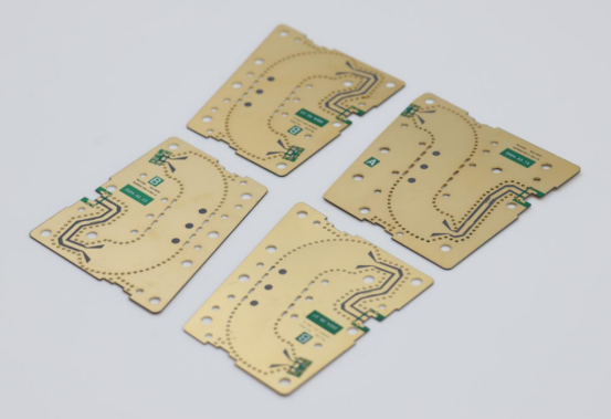
Substrate (Base Material): This is the foundation of the PCB, providing mechanical support and electrical insulation. Common substrate materials include FR-4, a fiberglass-reinforced epoxy laminate, and more specialized options like polyimide for high-temperature applications.
Conductive Traces: These copper pathways are responsible for transmitting electrical signals between components. The conductivity of the material is crucial for signal integrity, especially in high-speed or high-frequency circuits.
Insulating Materials: These materials prevent unwanted electrical connections (short circuits) and ensure that conductive traces are properly isolated from one another. Insulators, such as epoxy resin or polyimide, also help to manage the thermal stability of the PCB.
Substrate Materials: The Foundation of PCBs
What Are Substrate Materials?
Substrate materials are the base layers of a printed circuit board (PCB). Their primary function is to provide mechanical support to the PCB, holding all the components in place while ensuring electrical isolation between the conductive traces. This isolation is crucial for preventing short circuits and ensuring that signals flow along the correct paths. Additionally, substrate materials help manage heat, preventing components from overheating during operation.
Substrate materials are made to withstand environmental stress, such as temperature changes and mechanical pressure. The choice of substrate also plays a role in determining the thermal conductivity and dielectric properties of the PCB, both of which are important for signal integrity and long-term durability.
Common Types of Substrate Materials
There are several different types of substrate materials used in PCB manufacturing, each with distinct characteristics that make them suitable for different applications.
FR-4: The Standard Choice for Many Applications
FR-4 is the most commonly used substrate material in the PCB industry. It is a fiberglass-reinforced epoxy laminate that provides a solid balance of strength, insulation, and cost-effectiveness.
Composition and Benefits:
Strength: FR-4 offers good mechanical strength, making it durable and resistant to mechanical stresses.
Insulation: Its excellent electrical insulation properties help prevent unintended electrical connections, ensuring reliable performance.
Cost-Effectiveness: FR-4 is relatively inexpensive compared to other materials, making it a go-to choice for cost-sensitive applications.
Limitations:
High Dielectric Constant: FR-4 has a higher dielectric constant (4.2–4.6), which can reduce performance in high-frequency applications where signal integrity is critical.
Low Tg (Glass Transition Temperature): FR-4 typically has a Tg of around 130–150°C, making it unsuitable for applications that involve high temperatures or require long-term thermal stability.
Typical Use Cases:
Consumer Electronics: Smartphones, laptops, and other everyday devices where cost efficiency and standard performance are key.
Power Electronics: Power supplies and other applications that do not require extreme thermal or high-frequency performance.
CEM-1 and CEM-3: Budget-Friendly Alternatives
For simpler, cost-sensitive PCBs, CEM-1 and CEM-3 are viable alternatives to FR-4.
Differences Between CEM-1 (Single-Layer) and CEM-3 (Double-Layer):
CEM-1: Typically used for single-layer PCBs, CEM-1 is made of paper-based material combined with epoxy resin.
CEM-3: Suitable for double-layer designs, CEM-3 has better mechanical properties than CEM-1 but still lacks the strength and thermal stability of FR-4.
Pros:
Affordable: Both materials are cheaper than FR-4, making them ideal for simple PCBs where performance requirements are less demanding.
Suitable for Simpler Designs: CEM-1 and CEM-3 are great choices for low-cost applications such as toys, household electronics, and other non-critical devices.
Cons:
Lower Tg: CEM-1 has a Tg of 100–120°C, and CEM-3's Tg is slightly higher, but both are still less capable in high-temperature environments.
Moisture Absorption: These materials tend to absorb moisture, which can impact the long-term reliability of the PCB, especially in humid or high-moisture environments.
Rogers Materials: High-Performance Substrates
For high-performance applications that require superior signal integrity, Rogers materials are often the go-to choice.
Advantages for RF, Microwave, and Aerospace Applications:
Rogers substrates are designed for applications where signal loss, high-frequency performance, and thermal stability are critical. They are used in industries like telecommunications, aerospace, and advanced electronics.
Key Materials:
Rogers 4350B: Known for low dielectric loss and high thermal stability, this material is ideal for high-frequency applications.
Rogers 5880: A PTFE-based material with ultra-low loss and excellent performance at high frequencies, often used in microwave circuits and radar systems.
Performance Characteristics:
Low Dielectric Loss: Rogers materials exhibit very low loss factors (e.g., DF as low as 0.0009 for Rogers 5880), ensuring minimal signal degradation even in high-speed or high-frequency environments.
High Thermal Stability: With a Tg greater than 280°C for materials like Rogers 4350B, these substrates can withstand extreme temperatures without compromising performance.
When to Choose Rogers Materials:
Demanding Applications: Rogers materials are ideal when building PCBs for RF, microwave, or aerospace industries where performance and signal integrity are paramount.
High-Frequency Circuits: They are also suitable for circuits operating at frequencies beyond the capabilities of traditional substrates like FR-4, such as in telecommunications and radar systems.
Conductive Materials: Ensuring Efficient Signal Transmission
Importance of Conductive Materials in PCBs
In a printed circuit board (PCB), conductive materials play a pivotal role in ensuring efficient signal transmission and heat dissipation. These materials are the pathways through which electrical signals flow, connecting various components to make the device function as intended. Without high-quality conductive materials, PCBs would fail to carry signals effectively, leading to malfunctioning or inefficient devices.
Conductive materials are also crucial for heat dissipation. As electrical signals flow through the PCB, they generate heat, which must be managed to prevent overheating. Efficient conductive materials help to spread the heat away from sensitive components, ensuring the PCB operates within safe thermal limits.
There are trade-offs involved when choosing conductive materials for PCBs. While copper offers exceptional conductivity, it is heavy and prone to oxidation. Aluminum, on the other hand, is lightweight and cost-effective but has lower conductivity. Balancing conductivity, weight, and cost is essential when designing a PCB for specific applications.
Key Conductive Materials
Copper: The Industry Standard
Copper is the most widely used conductive material in PCBs, known for its excellent electrical conductivity and ease of processing.
Exceptional Electrical Conductivity:
Copper provides one of the best conductivity levels of any material, ensuring that electrical signals pass through the PCB with minimal resistance. This is critical for high-speed circuits, where signal integrity is paramount.
Ease of Etching and Plating:
Copper is easy to work with during the manufacturing process. It can be etched into intricate patterns and plated to create thin conductive traces, making it ideal for complex PCB designs.
Issues with Oxidation and How It's Managed:
One of the downsides of copper is that it is prone to oxidation, which can impair conductivity over time. To combat this, copper traces are often coated with protective metals like gold or nickel. These coatings prevent oxidation and ensure long-lasting performance. Gold, in particular, is commonly used for high-precision applications, as it provides excellent corrosion resistance and reliability.
Aluminum: Lightweight Alternative
Aluminum is an alternative conductive material that offers distinct advantages in certain applications, especially where weight and cost are critical factors.
Lower Conductivity but Cost-Effective and Lightweight:
Although aluminum has lower electrical conductivity than copper, it is significantly lighter and less expensive. This makes it a suitable choice for applications where weight savings and cost efficiency are more important than ultra-high conductivity. For example, aluminum is commonly used in automotive and LED lighting applications, where reducing weight is a priority.
Suitable for Applications Where Weight and Cost Are Primary Concerns:
In industries such as automotive electronics or LED technology, the lightweight nature of aluminum can reduce the overall weight of the device, which is important for both performance and energy efficiency. Furthermore, its lower cost makes it a viable option for high-volume production of PCBs for cost-sensitive products.
Protective Coatings Needed to Prevent Corrosion:
Like copper, aluminum is also susceptible to corrosion when exposed to moisture and air. To maintain its durability and ensure consistent performance, aluminum traces are typically coated with a protective layer, such as anodizing or a nickel coating. These coatings prevent oxidation and extend the lifespan of aluminum-based PCBs.
Insulating Materials: Preventing Electrical Short Circuits
The Role of Insulation in PCB Functionality
Insulating materials in a printed circuit board (PCB) are essential for preventing electrical short circuits and ensuring safe, reliable operation. These materials provide the necessary barrier between conductive traces, ensuring that signals only flow along the intended paths and preventing unwanted electrical connections that could disrupt the circuit's functionality.
Beyond simply preventing short circuits, insulating materials also contribute to the overall electrical safety of the PCB. They help manage the thermal stability of the board by resisting heat buildup, which is crucial for maintaining performance over time, especially in high-power or high-frequency applications.
In short, insulation is key to both the electrical integrity and the safety of a PCB, ensuring it performs optimally without risk of malfunction due to unintended electrical contact.
Common Insulating Materials
There are several types of insulating materials used in PCB manufacturing, each with its own unique properties and applications. The most common insulating materials include epoxy resin and polyimide, which are selected based on factors such as cost, performance requirements, and operating conditions.
Epoxy Resin: Cost-Effective and Versatile
Epoxy resin is one of the most widely used insulating materials in PCB manufacturing due to its balance of cost-effectiveness and good electrical insulation properties.
Good Electrical Insulation Properties:
Epoxy resin is an excellent electrical insulator, preventing unintended electrical connections between conductive traces. Its insulating properties help ensure that signals remain isolated and flow along the correct paths, critical for maintaining the overall performance of the PCB.
Issues with Brittleness and Curing Challenges:
While epoxy resin is an affordable and effective insulating material, it does have some drawbacks. It tends to be brittle under mechanical stress, which can lead to cracking or damage during handling or in high-stress environments. Additionally, epoxy resin requires high curing temperatures, which can present challenges in manufacturing processes that need precise control over temperature.
Typical Uses:
Epoxy resin is commonly used in consumer electronics and general-purpose PCBs where cost is a concern but reliable insulation is still necessary. It is typically found in devices like smartphones, computers, and home appliances.
Polyimide: High-Performance Insulation
Polyimide is a high-performance insulating material that excels in applications where durability and heat resistance are paramount.
Superior Heat Resistance (Up to 260°C):
One of the standout features of polyimide is its exceptional heat resistance. It can withstand temperatures of up to 260°C, making it ideal for applications where the PCB is exposed to extreme heat, such as in automotive or aerospace environments.
Electrical Stability and Durability:
Polyimide offers superior electrical stability and durability, ensuring that the PCB maintains consistent performance even under harsh operating conditions. This makes polyimide a preferred choice for high-end, mission-critical applications where reliability is non-negotiable.
Cost Considerations and Applications in High-End Industries:
While polyimide offers outstanding performance, it comes with a higher price tag compared to other insulating materials like epoxy resin. Due to its cost, it is typically used in high-performance industries such as aerospace, and automotive electronics, where the added durability and heat resistance justify the investment.
Auxiliary Materials: Enhancing PCB Durability and Functionality
Supporting Materials in PCB Production
In addition to the primary materials like substrates, conductive traces, and insulators, auxiliary materials play a vital role in enhancing the overall durability, functionality, and usability of a printed circuit board (PCB). These materials serve to protect the board, make assembly easier, and improve the performance of the PCB over its lifetime.
Common auxiliary materials include solder mask and silkscreen. While not directly involved in conducting electrical signals, these materials are essential for ensuring the PCB operates effectively in real-world conditions and during assembly.
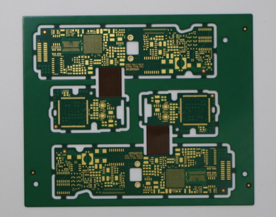
Solder Mask
The solder mask is a key protective layer applied to the surface of a PCB. It serves several critical functions, particularly in protecting the conductive traces and ensuring the long-term reliability of the board.
Function in Protecting Conductive Traces from Oxidation and Physical Damage:
The primary function of the solder mask is to prevent the copper traces on the PCB from coming into direct contact with the environment. Without the solder mask, copper would be exposed to air and moisture, leading to oxidation and corrosion. This oxidation can degrade the performance of the PCB and increase the likelihood of short circuits. The solder mask also protects the traces from mechanical damage, dirt, and dust during assembly and handling.
Types of Solder Masks:
There are several types of solder masks, each offering different aesthetic and functional properties:
Green Solder Mask: The most common type used in PCB manufacturing, known for its visibility during inspection and good durability.
Black Solder Mask: Often used for aesthetic purposes or in situations where high-contrast visibility is needed.
White Solder Mask: Typically used for specialized applications where bright contrast is required for component identification.
Other Colors: Depending on the product’s design or branding, solder masks can also come in red, blue, yellow, or other colors. These offer similar protective properties but are chosen for visual appeal or specific customer preferences.
Application Process via Photolithography:
The solder mask is applied using photolithography, a process that involves coating the PCB with a layer of photo-sensitive material. The board is then exposed to ultraviolet (UV) light through a mask, hardening the material in the areas that are not covered by the photo-mask. The unexposed areas are then washed away, leaving a thin, protective layer over the copper traces. This process allows for precise control over which areas of the PCB are covered by the solder mask.
Silkscreen
The silkscreen layer is another auxiliary material that plays a crucial role in the assembly and maintenance of the PCB. It provides a means of labeling components and other important information directly on the surface of the board.
Purpose in Labeling Components for Assembly and Troubleshooting:
The silkscreen is used to mark component locations, part numbers, and other important data such as brand logos or circuit diagrams on the PCB. This labeling helps technicians easily identify components during assembly, making it quicker and more accurate. It also aids in troubleshooting, allowing engineers to visually locate and identify components when testing or repairing the PCB.
Durable Ink Options (White, Black) and Their Significance:
The ink used for silkscreen printing is typically a durable, heat-resistant white or black ink. These inks are chosen because they are both visible under various lighting conditions and can withstand the heat that the PCB may be exposed to during operation or soldering. White is commonly used for high contrast and easy readability, while black is often used for a more understated, professional appearance.
How Silkscreen Aids in Efficient Manufacturing and Maintenance:
Silkscreen printing makes the manufacturing process more efficient by providing clear, legible labels that ensure components are placed correctly. This reduces the chances of mistakes during assembly and helps to prevent errors like incorrect component placement or misidentification. Additionally, the silkscreen aids in the maintenance phase by making it easier for engineers to identify the components that need to be tested or replaced, which streamlines repairs and upgrades.
Selecting the Right Materials for Your PCB
Factors to Consider When Choosing PCB Materials
Choosing the right materials for your PCB is critical to its performance, reliability, and cost-effectiveness. The selection process must balance several key factors, including electrical, thermal, and mechanical requirements, as well as budget considerations.
Electrical Requirements (High-Frequency Performance, Conductivity Needs):
Depending on the application, the PCB may need to support high-frequency signals (e.g., RF or microwave circuits) or handle specific conductivity levels for optimal signal transmission. For high-frequency applications, materials with low dielectric loss and high thermal stability, such as Rogers materials, are often required. For general consumer electronics, FR-4 might suffice due to its affordability and adequate performance at lower frequencies.
Thermal and Mechanical Demands (Aerospace, Automotive, Consumer Electronics):
Certain industries, like aerospace or automotive, demand materials that can withstand extreme temperatures, mechanical stresses, or vibration. Polyimide is a preferred choice for high-temperature environments due to its excellent heat resistance. On the other hand, FR-4 is often used in consumer electronics where thermal and mechanical demands are lower, and cost-effectiveness is more important.
Budget Considerations (Cost-Effective Options for Mass Production):
Budget plays a significant role, particularly for mass-produced consumer electronics. While high-performance materials like Rogers are necessary for specialized applications, they may not be suitable for products requiring high-volume production. For cost-effective solutions, materials such as CEM-1 and CEM-3 offer more affordable alternatives for simpler PCBs with less demanding performance criteria.
Step-by-Step Process for Material Selection
Selecting the right materials for your PCB is a methodical process that involves understanding the project’s requirements and evaluating the properties of various materials. Follow these steps to make an informed choice:
Understanding Project Requirements (Performance, Durability, Cost):
Begin by clarifying the specific needs of the project. Is the PCB required to handle high-speed signals, operate in extreme conditions, or be mass-produced for consumer electronics? Understanding the balance between performance, durability, and cost will guide your decision-making process.
Analyzing Material Properties (Dielectric Constant, Thermal Stability, Mechanical Strength):
Each material has unique properties that can affect the performance of the PCB:
Dielectric constant impacts signal speed and quality, especially in high-frequency designs.
Thermal stability ensures the PCB can handle the operating temperatures without degrading.
Mechanical strength determines how well the PCB will withstand physical stress, which is essential for industries like automotive and aerospace.
For example, Rogers 4350B offers low dielectric loss and high thermal stability for high-frequency, high-performance applications, while FR-4 offers adequate mechanical strength at a lower cost for everyday consumer products.
Consulting with Experts for Tailored Recommendations:
When in doubt, consult with PCB manufacturers or material suppliers. Their expertise can provide valuable insights into which materials best suit your application, considering factors like environmental conditions, electrical requirements, and manufacturing constraints. Consulting with experts ensures that you avoid common pitfalls and select the most suitable materials for your project.
Example: Selecting Materials for an RF PCB vs. a Power Supply PCB:
RF PCB: For high-frequency designs like RF circuits, materials with low dielectric loss and stable performance at high frequencies are essential. Rogers 5880 is a common choice due to its low loss factor and high thermal stability, making it ideal for telecommunications or microwave applications.
Power Supply PCB: For a power supply PCB, FR-4 or CEM-3 may suffice, as these materials offer good mechanical strength and insulation at a more affordable price point. The focus here is on the board’s ability to handle heat dissipation and provide electrical insulation rather than signal integrity at high frequencies.
Conclusion
Choosing the right materials for your PCB is crucial for achieving optimal performance, durability, and cost-efficiency. Whether you're designing a high-frequency RF circuit or a cost-effective consumer electronics PCB, selecting the appropriate materials ensures the board can handle electrical, thermal, and mechanical demands while staying within budget.
With expertise and experience, manufacturers can tailor material selections to suit specific applications, from aerospace to automotive and consumer electronics. Understanding material properties—such as dielectric constant, thermal stability, and mechanical strength—is essential for making informed decisions that enhance the functionality and longevity of the PCB.
Looking ahead, as technology becomes more complex, the demand for specialized PCB materials will only increase. Innovations in materials science will continue to drive improvements in performance, miniaturization, and sustainability, making it exciting to explore the future of PCBs in the evolving tech landscape.
If you have any questions or want to learn more about PCB materials, feel free to contact PCBMASTER. As an experienced PCB supplier, we offer professional guidance and solutions tailored to your unique needs.
FAQs
What are the most common materials used in PCB manufacturing?
The most common materials used in PCB manufacturing include:
Substrate materials: FR-4, CEM-1, CEM-3, and high-performance options like Rogers materials.
Conductive materials: Copper is the industry standard for most PCBs due to its excellent conductivity, while aluminum is used for lighter, cost-effective solutions.
Insulating materials: Epoxy resin is widely used for general applications, while polyimide is favored for high-performance, high-temperature environments.
Auxiliary materials: Solder mask and silkscreen are essential for protection and labeling.
Each material has its specific properties and applications based on factors like performance, cost, and industry requirements.
How do I choose the best substrate material for my PCB project?
To choose the best substrate material for your PCB project, consider the following factors:
Electrical requirements: For high-frequency applications, materials like Rogers with low dielectric loss are ideal. For general consumer electronics, FR-4 is typically sufficient.
Thermal stability: Materials like polyimide offer superior heat resistance for high-temperature environments, while FR-4 works well in standard conditions.
Mechanical properties: Consider the strength and durability needed for your application, especially in industries like aerospace or automotive.
Cost: Balance performance with cost, especially for mass-produced PCBs. CEM-1 and CEM-3 are more affordable alternatives to FR-4.
By understanding the specific demands of your project, you can select a substrate that aligns with your performance, durability, and budget goals.
What factors affect the performance of PCB conductive materials?
The performance of PCB conductive materials is influenced by several key factors:
Electrical conductivity: Materials like copper offer excellent conductivity, ensuring efficient signal transmission.
Thermal conductivity: Efficient heat dissipation is crucial, particularly in high-power applications. Copper is a good choice for heat management, but aluminum may also be used where weight is a concern.
Corrosion resistance: Copper is prone to oxidation, which can affect performance over time. Coatings like gold or nickel are applied to prevent corrosion.
Material thickness: The thickness of the conductive traces impacts resistance and current-carrying capacity. Thicker traces are used in high-power applications.
Understanding these factors will help you select the right conductive material to ensure optimal PCB performance.
How can I ensure that my PCB design avoids short circuits?
To prevent short circuits in your PCB design, consider the following steps:
Use proper insulation: Ensure that insulating materials like epoxy resin or polyimide are used effectively to separate conductive traces.
Implement adequate spacing: Maintain proper trace width and spacing based on voltage levels and current carrying requirements to avoid accidental shorts.
Apply solder mask: The solder mask layer protects the PCB from oxidation and physical damage, ensuring that conductive traces remain intact and isolated.
Avoid moisture: Moisture can lead to short circuits, so use moisture-resistant materials and ensure proper sealing during assembly.
Conduct thorough testing: Perform electrical testing (e.g., continuity and impedance testing) during the manufacturing process to detect potential issues before the PCB is used.
By following these guidelines, you can ensure that your PCB design is robust and free from short circuits.
What are the latest trends in PCB materials for high-tech industries?
The latest trends in PCB materials are driven by the increasing demand for faster, more efficient, and compact devices across high-tech industries. Some of the key trends include:
High-performance materials: Materials like Rogers and ceramic-based substrates are becoming more prevalent in 5G, RF, and microwave applications due to their low dielectric loss and high thermal stability.
Flexible PCBs: The use of flexible materials, such as polyimide and flexible laminates, is growing in wearable electronics, medical devices, and automotive applications, enabling more compact and adaptable designs.
Advanced heat management: As devices become more powerful, materials that offer enhanced thermal conductivity (e.g., graphene and ceramic-based PCBs) are being incorporated to improve heat dissipation and prevent overheating.
Environmentally friendly materials: There's a growing push towards using lead-free and halogen-free materials in PCB manufacturing, driven by environmental regulations and sustainability concerns.
Multi-layer and high-density interconnect (HDI) PCBs: High-density boards that enable more complex circuits are in demand, particularly in smartphones, IoT devices, and advanced computing applications.
These trends reflect the increasing complexity of modern electronics and the need for materials that can meet demanding performance, thermal, and environmental standards.