


Optimizing FPC Connections for Peak Performance in Modern Electronics
As the demand for sleeker, more sophisticated devices grows, ensuring that every connection within them performs flawlessly is critical. Traditional cables, while reliable in the past, struggle to meet the needs of today's compact, flexible designs. This is where FPC connection performance comes into play. FPCs are not just an upgrade; they are a game-changer, offering unmatched flexibility and reliability.
Introduction to FPCs and Their Role in Modern Electronics
What Are FPCs?
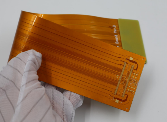
FPCs (Flexible Printed Circuits) are an advanced type of electrical connection used in modern electronics. Unlike traditional rigid wires, FPCs are made from flexible materials, allowing them to bend and move without breaking. This makes them perfect for devices that need to be compact, lightweight, and durable.
Core Components of FPCs:
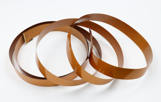
Flexible Substrate: This is the thin, flexible base that forms the body of the FPC. Common materials include polyimide and polyester, which provide strength and flexibility.
Conductive Traces: These are the pathways made of copper or other metals that carry electrical signals and power. The traces are printed or etched onto the flexible substrate.
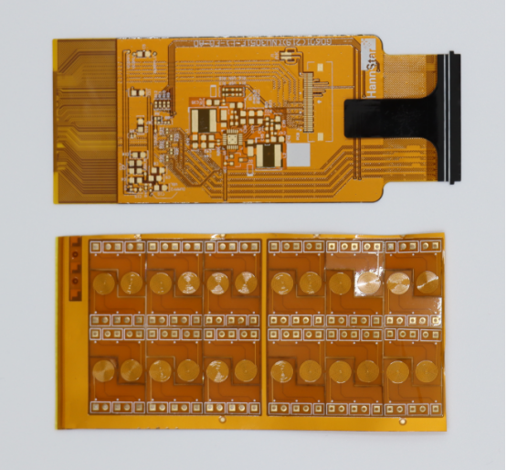
Connectors: FPCs use connectors to link the flexible circuits to other parts of the device. These can be ZIF (Zero Insertion Force) connectors or IDC (Insulation Displacement Contact) Connectors, depending on the device’s needs.
Significance in the Electronics Industry:
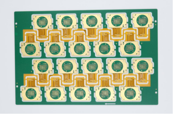
FPCs are crucial for modern electronics because they enable new product designs. For example, they allow devices to be smaller, more flexible, and more reliable than traditional wiring methods. FPCs have revolutionized industries such as consumer electronics, medical devices, and automotive sectors by offering solutions where rigid wires would be too bulky or fragile.
Why Connection Performance Matters for Devices Using FPCs
FPCs are used in devices that require flexible, reliable, and long-lasting connections. These devices often have to endure movement, vibration, and stress while maintaining stable electrical signals. The performance of FPC connections directly affects how well the device functions, making connection reliability a critical factor.
Importance of Reliable, Stable Connections:
In any device using FPCs, whether it’s a wearable or a medical sensor, the connections must remain stable even as the device moves or bends. Poor connection performance can lead to failures, such as loss of signal or even device breakdowns. This is especially true for applications where the device is subject to constant motion, such as in foldable phones or wearable fitness trackers.
Connection Performance Challenges in Dynamic Devices:
In dynamic devices, such as robots or wearables, the FPCs need to perform well under stress. These devices often experience vibrations, frequent movement, and even harsh environmental conditions (like temperature changes). To handle these challenges, FPCs must be designed with robust, flexible materials and connectors that can withstand these demands while maintaining reliable electrical performance.

Understanding FPC Connection Performance: Key Factors
Flexibility and Signal Integrity
How FPCs Maintain Signal Integrity in Dynamic Environments
FPCs are designed to work effectively in environments where movement, bending, and twisting are common. Unlike traditional rigid wires, FPCs can bend without losing signal quality. This is especially important in modern electronics, where devices like foldable phones, wearables, and medical sensors need to maintain performance despite continuous movement.
Advantages of FPCs in Reducing Signal Loss:
FPCs are made from flexible materials that allow them to bend and twist while maintaining a steady electrical connection. The conductive traces on FPCs are designed to resist degradation during these movements, reducing the chance of signal loss. This ability to maintain signal quality, even when the circuit is bent, makes FPCs ideal for applications where the device needs to flex repeatedly without compromising performance.
Material Properties that Ensure Robust Signal Transmission:
The materials used in FPCs, such as polyimide for the substrate and copper for the conductive traces, play a significant role in ensuring strong signal transmission. Polyimide is known for its high-temperature resistance, flexibility, and electrical insulation properties. Copper traces, which are thin and tightly packed, enable fast and reliable signal transfer, even when the circuit is flexed or bent.
The Impact of Bend Radius on Signal Quality
The bend radius refers to the minimum curve that an FPC can make without damaging its conductive traces or affecting its performance. The bend radius is a crucial factor in maintaining signal integrity.
Defining and Calculating Bend Radius:
The bend radius is calculated based on the thickness of the FPC. A general rule is that the bend radius should be at least 10 times the thickness of the FPC. For example, if the FPC is 0.1mm thick, the minimum bend radius would be 1mm. This ensures that the circuit can bend without placing excessive stress on the traces, which could lead to signal loss or physical damage.
Consequences of Exceeding Bend Radius and Signal Degradation:
If the bend radius is too tight, the FPC may experience problems such as signal degradation, trace damage, or even a complete failure of the circuit. Tight bends cause stress on the copper traces, leading to cracks or breaks that can disrupt the electrical signal. In some cases, the FPC might even tear, making the device inoperable.
Durability and Long-Term Performance
Resistance to Mechanical Stress: A Comparative Analysis
FPCs are known for their durability, especially when compared to traditional cables. Their flexible nature allows them to withstand repeated bending and movement, making them ideal for devices that require constant motion, such as robots, wearables, and automotive systems.
Comparing FPCs vs Traditional Cables:
Traditional cables are usually rigid and can easily break or lose their connections when bent too many times. In contrast, FPCs are made from materials that allow them to handle thousands of bends without compromising their electrical connections. This makes FPCs much more reliable over time, especially in applications where the device is in constant motion.
Real-World Applications Where Durability is Critical:
Robotics: Robots often need to move and bend in different directions. FPCs help maintain the integrity of electrical connections despite the constant motion, reducing the risk of failure.
Automotive: In automotive systems, FPCs are used to connect sensors, infotainment systems, and other electronics that may be exposed to vibration and movement. FPCs’ ability to maintain signal integrity under these conditions makes them ideal for use in vehicles.
How Environmental Factors Affect FPC Connection Longevity
The lifespan of an FPC is also influenced by environmental factors such as moisture, temperature fluctuations, and exposure to chemicals. For devices used in harsh environments, the FPC must be able to withstand these elements without degrading.
Protection from Moisture, Temperature Fluctuations, and Chemical Exposure:
FPCs are often coated with protective materials like polyimide or a coverlay to shield them from moisture, temperature extremes, and harsh chemicals. These coatings help prevent damage from water, dirt, or oils, which can cause corrosion or electrical failures. Polyimide, in particular, is highly resistant to temperature changes, making it ideal for applications in extreme environments.
The Role of Polyimide and Coverlay Materials in Extending FPC Lifespan:
Polyimide not only provides flexibility but also offers excellent thermal stability and chemical resistance, which helps extend the lifespan of FPCs. The coverlay materials, which are applied over the traces, offer additional protection from abrasion, moisture, and other environmental factors. By preventing direct exposure to these elements, FPCs can last longer and maintain reliable connections throughout their operational life.
Installation and Connector Choices: Ensuring Reliable FPC Connections
Connector Selection and Its Impact on Performance
Types of FPC Connectors: ZIF vs IDC
When installing FPCs, choosing the right connector is crucial to ensuring a strong, reliable connection. There are two common types of FPC connectors: ZIF and IDC. Both connectors serve different purposes depending on the device's needs.
ZIF Connectors:
ZIF connectors are designed to connect delicate FPCs without putting stress on the thin traces. These connectors use a lever or latch mechanism, allowing the FPC to be inserted easily without forcing the connector into place. The primary benefit of ZIF connectors is their ability to handle fragile circuits. They are commonly used in devices that need to be frequently assembled or disassembled, such as foldable phones and laptop screens. ZIF connectors help maintain the integrity of the FPC by preventing mechanical stress during installation and removal.
IDC Connectors:
IDC connectors are typically used for mass production where speed and efficiency are priorities. These connectors feature sharp blades that pierce through the insulation of the FPC to establish a connection with the conductive traces. IDC connectors are ideal for high-volume devices like consumer electronics (e.g., wireless earbuds, smartphones) because they don’t require soldering and can be applied quickly. However, they are less suited for delicate, low-power FPCs, as the pressure from the blades can sometimes damage the thin copper traces.
How to Choose the Right Connector for Your Application
Choosing the right FPC connector depends on several factors, such as the type of device, required performance, and environmental conditions.
Factors to Consider:
Pitch Size: This refers to the spacing between pins on the connector. FPCs with finer pitch sizes (e.g., 0.5mm) need connectors that match the tight spacing of the traces.
Pin Density: If your device requires high-density connections (e.g., foldable phones), choosing connectors with a higher pin count ensures you can achieve the needed electrical connections without sacrificing space.
Current Ratings: Different connectors are designed to handle varying amounts of current. For high-power devices (e.g., automotive sensors), ensure the connector can support the required amperage.
Environmental Protection: For devices exposed to moisture, dust, or chemicals (e.g., medical sensors or automotive systems), choose connectors with high IP ratings (Ingress Protection) to protect the FPC from damage.
Use Case Examples:
Foldable Phones: These devices require ZIF connectors because they need flexibility and easy disassembly for repairs, ensuring the connectors don’t put stress on the FPC during frequent folding.
Medical Devices: In medical equipment like portable ultrasound probes, IDC connectors may be used for high-volume, reliable connections, especially in environments where devices are exposed to sterilization processes and temperature fluctuations.
Proper FPC Installation to Minimize Performance Issues
Step-by-Step Guide for Installing FPCs
Proper installation is key to achieving optimal FPC connection performance. Follow these steps to ensure a secure and reliable connection:
1. Essential Pre-Installation Steps:
Before connecting the FPC, take the following preparatory actions:
Cleaning: Use isopropyl alcohol (90% or higher) and a lint-free cloth to clean both the FPC and connectors. Any dust, grease, or residue can cause poor contact or signal loss.
Static Control: Static electricity can damage the FPC. Always wear an anti-static wrist strap and work on an anti-static mat to prevent static buildup.
Pre-Tinning Connectors: Apply a thin layer of solder to the connector pins (using a temperature-controlled soldering iron set between 300–320°C). This makes the final connection stronger and more reliable.
2. Detailed Installation Instructions:
Aligning FPCs: Carefully align the FPC’s conductive traces with the connector pins. Ensure the FPC is flat against the connector to avoid misalignment.
Securing the Connection: For ZIF connectors, gently insert the FPC and secure it by closing the lever or latch. For IDC connectors, apply even pressure to the connector to pierce the FPC insulation and establish contact.
Testing Electrical Continuity: After installation, use a multimeter to check that each trace is correctly connected. This will ensure that there are no open or short circuits.
The Role of Strain Relief in Enhancing Connection Stability
Strain relief is an important step in FPC installation that often gets overlooked. It prevents mechanical stress from damaging the FPC or its connectors over time, ensuring the circuit maintains reliable performance.
Importance of Strain Relief (Kapton Tape, Heat Shrink Tubing):
Strain relief materials like Kapton tape or heat shrink tubing help distribute tension near the connector, preventing the FPC from bending excessively at critical points. This is especially useful in applications where the device moves or bends, such as wearables or robotics. Applying strain relief ensures that the connector isn’t exposed to constant stress, which could lead to premature failure.
How Improper Strain Relief Can Lead to Premature Failure:
Without proper strain relief, the FPC can experience stress at the connector joints, leading to trace breakage or loosening of the connection. Over time, this can cause signal loss, intermittent connection issues, or total failure of the device. For example, in a wearable device, if the FPC near the connector isn’t properly secured, frequent bending could result in damaged traces, causing the device to stop working.
Common Issues with FPC Connections and How to Address Them
Troubleshooting FPC Connection Failures
Diagnosing and Solving Signal Integrity Issues
Signal integrity is crucial for the proper function of FPCs. When signal loss or intermittent connections occur, it can affect the performance of electronic devices. Common issues include:
Intermittent Connections: This happens when the signal cuts in and out due to poor contact between the FPC and the connector.
Loss of Signal Quality: In some cases, the signal may weaken or degrade over time, making the device unreliable.
Solutions:
Cleaning Connectors: One of the most common causes of signal issues is dirty or oxidized connectors. Regular cleaning with isopropyl alcohol (90% or higher) and a lint-free cloth can remove contaminants that interfere with the electrical connection.
Re-Seating Connectors: If a connection is loose, it can lead to an unstable signal. Gently reseating the connector or reconnecting the FPC properly can restore the signal quality.
Solder Joint Repairs: If the FPC connection is damaged, the solder joint might have cracked or broken. Reflowing the solder or adding fresh solder can repair the joint and restore proper electrical flow.
By addressing these issues early, you can prevent further damage and ensure the signal integrity of your FPC connections.
Preventing and Fixing Mechanical Failures (Cracking, Tearing)
FPCs, especially in devices with moving parts, are prone to mechanical failures such as cracking, tearing, or delamination. These failures often occur in dynamic applications where the FPC is subject to constant bending, twisting, or vibration. Key issues include:
Trace Damage: Bending an FPC beyond its recommended bend radius can cause the copper traces to crack, leading to signal loss or complete failure.
Delamination: This occurs when the layers of the FPC peel apart due to excessive stress or environmental factors.
Breakage: In extreme cases, the FPC itself may tear, especially around connectors where mechanical forces are concentrated.
Fixes and Preventive Steps:
Adjusting Bend Radius: Ensure that the FPC is bent within the recommended bend radius (typically 10x the thickness of the FPC). Bending it too tightly can cause the traces to crack and lead to permanent damage.
Adding Reinforcement: Areas where the FPC experiences the most stress (e.g., near connectors) can benefit from added reinforcement. Using stiffeners like FR4 or polyimide can prevent bending in critical areas and help distribute stress evenly.
Using Tear Guards: For high-stress areas, add tear guards, which are extra layers of polyimide, to protect the FPC from cracking or tearing during movement.
By taking these preventive measures, you can significantly extend the lifespan of your FPCs and ensure the device remains functional under dynamic conditions.
Best Practices to Extend FPC Connection Lifespan
Preventive Maintenance for FPCs
Maintaining the reliability of FPC connections requires regular checks and proper handling. Preventive maintenance ensures that potential issues are addressed before they lead to device failure.
Monthly Inspection Guidelines:
Checking Connectors: Regularly inspect the connectors for signs of wear, dirt, or corrosion. Clean them thoroughly to ensure that electrical contact remains stable.
Testing Continuity: Use a multimeter to check the electrical continuity of the FPC traces. This helps detect any interruptions or breaks in the circuit.
Inspecting Strain Relief: Check strain relief mechanisms (e.g., Kapton tape or heat shrink tubing) to make sure they are intact and properly securing the FPC in place. If they are damaged or loose, replace them to prevent further mechanical stress on the FPC.
Regular Cleaning and Handling Tips:
Avoiding Static Damage: Always work in anti-static environments, using wrist straps and mats to prevent electrostatic discharge (ESD), which can damage FPCs. When handling FPCs, always wear ESD-safe gloves.
Preventing Contamination: Ensure that no oils, dirt, or moisture come into contact with the FPC. Contaminants can degrade the copper traces and lead to connection failures.
Long-Term Storage and Handling Recommendations
Proper storage and handling are essential to protect FPCs from damage when they are not in use or during the assembly process. Proper care can prevent issues like static buildup, physical damage, and environmental exposure.
Proper Storage Techniques:
Flat Storage: Store FPCs flat to prevent bending or deformation. Use anti-static bags or ESD-safe trays to protect them from electrostatic discharge and contamination.
Controlled Environment: Store FPCs in a cool, dry place, away from direct sunlight. Avoid areas with high humidity, as moisture can cause the FPC to degrade over time.
Tips for Working with FPCs in Assembly:
Using Anti-Static Tools: Always use anti-static tools like tweezers or soldering irons to handle the FPC during assembly. This minimizes the risk of ESD damage.
Using Proper Jigs: Ensure the FPC is secured properly during the assembly process. Use jigs or fixtures to hold the FPC in place and prevent unnecessary bending or twisting that could lead to damage.
By following these long-term storage and handling practices, you can ensure that your FPCs remain in optimal condition and ready for use whenever needed.
Conclusion
FPCs are transforming modern electronics by offering unmatched flexibility, durability, and space efficiency. These qualities make FPCs ideal for applications like wearables, medical devices, and foldable smartphones, where traditional cables would be too bulky or prone to failure. FPC connections, essential for maintaining signal integrity in dynamic environments, ensure reliable performance even as devices bend, twist, and fold.
To fully optimize FPC connections, attention must be paid to connector selection, signal integrity, and durability. Factors like moisture resistance, temperature stability, and mechanical stress directly influence the long-term performance of FPC connections.
For those looking to maximize FPC connection reliability, PCBMASTER offers specialized solutions. With over 100 successful projects across industries such as aerospace, medical, and automotive, PCBMASTER delivers ultra-flexible, high-precision circuits that ensure superior FPC connection performance. Their expertise and commitment to innovation make them a trusted partner for creating future-ready, high-performance devices.
FAQs
Can FPCs Handle High-Power Applications Like Traditional Cables?
While FPCs excel in flexibility, durability, and space efficiency, they are generally not suitable for high-power applications like traditional cables. Standard FPCs typically handle low-to-medium power (up to 3A per trace), making them ideal for devices like sensors, displays, and wearables. For high-power applications, such as electric vehicle batteries or industrial motors, traditional cables made from thicker, more robust materials are still required. However, high-power FPCs can be designed with thicker traces and specialized materials for applications that require higher power handling.
What’s the Maximum Bend Limit for an FPC Without Compromising Connection Performance?
The maximum bend radius for an FPC varies based on its thickness and application. As a rule of thumb, the bend radius should be at least 10 times the thickness of the FPC. For example, if the FPC is 0.1mm thick, the minimum bend radius should be 1mm. Bending the FPC beyond this limit can lead to trace damage, signal loss, or connection failure. It’s essential to adhere to this guideline to maintain long-term performance, especially in dynamic applications like wearable devices or robotic systems.
How Can I Test an FPC Connection for Signal Loss or Continuity?
Testing FPC connections for signal loss or continuity is simple with basic tools like a multimeter or oscilloscope. For continuity testing, set the multimeter to the continuity mode and check the traces for a complete circuit, ensuring there are no breaks or shorts. For signal integrity, use an oscilloscope to measure the signal quality at the FPC’s output. If the signal shows excessive noise or loss, this indicates an issue with the connection or traces that needs to be addressed.
Are FPCs Suitable for Use in Extreme Environments Like Automotive or Medical Devices?
Yes, FPCs are well-suited for harsh environments, including automotive and medical devices, due to their durability and resistance to environmental stressors. In automotive applications, FPCs can handle vibration, temperature fluctuations, and moisture, making them ideal for sensor wiring or infotainment systems. In the medical field, FPCs are used in compact devices like pacemakers and ultrasound probes, where their small size and resistance to sterilization chemicals make them highly effective. To ensure long-term reliability, it’s important to select FPCs with polyimide coverlays or other protective coatings to shield against moisture, temperature, and mechanical wear.
How Do I Prevent FPC Connector Damage During Installation?
FPC connectors are delicate and require careful handling during installation to prevent damage. Here are some best practices to avoid connector issues:
1. Handle with Care: Always handle FPCs by the edges to avoid pressure on the traces or connectors.
2. Use Proper Tools: Use a temperature-controlled soldering iron and anti-static equipment (e.g., wrist straps) to prevent static discharge or overheating.
3. Align Connectors Correctly: Ensure the FPC traces align precisely with the connector pins before securing them. For ZIF connectors, gently close the latch without applying force.
4. Add Strain Relief: Apply Kapton tape or heat shrink tubing near the connectors to absorb pull forces and prevent damage from mechanical stress.
By following these steps, you can ensure secure, lasting connections that will maintain signal integrity and avoid premature failure.
Author Bio
Hi, I'm Carol, the Overseas Marketing Manager at PCBMASTER, where I focus on expanding international markets and researching PCB and PCBA solutions. Since 2020, I’ve been deeply involved in helping our company collaborate with global clients, addressing their technical and production needs in the PCB and PCBA sectors. Over these years, I’ve gained extensive experience and developed a deeper understanding of industry trends, challenges, and technological innovations.
Outside of work, I’m passionate about writing and enjoy sharing industry insights, market developments, and practical tips through my blog. I hope my posts can help you better understand the PCB and PCBA industries and maybe even offer some valuable takeaways. Of course, if you have any thoughts or questions, feel free to leave a comment below—I’d love to hear from you and discuss further!

