


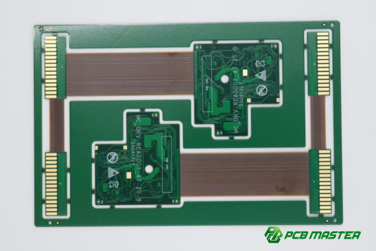
Flexible PCB SMT Assembly: How It Differs from Rigid PCB Assembly
Flexible printed circuit boards (PCBs) are playing an increasingly important role in modern electronics. The global flexible PCB market is projected to reach USD 50.9 billion by 2030, growing at a compound annual growth rate (CAGR) of 13.7% from 2025 to 2030. Compared to rigid PCBs, flexible boards allow devices to be thinner, lighter, and more adaptable, making them ideal for smartphones, wearable devices, medical instruments, and automotive electronics.
As flexible PCBs become more widely used, engineers face unique challenges during SMT (surface mount technology) assembly. Unlike rigid boards, flexible PCBs are prone to bending, warping, and different responses to thermal stress, which can affect soldering quality and overall device reliability.
So how can these challenges be addressed? In this article, PCBMASTER shares its extensive industry experience to help engineers understand the key differences between flexible and rigid PCB SMT assembly. We will explore material properties, structural considerations, thermal management strategies, and SMT techniques to provide a clear, practical guide for successful assembly.
What Are the Key Differences Between Flexible and Rigid PCB SMT Assembly?
Flexible PCB SMT assembly differs from rigid PCB assembly mainly in materials, structural handling, and thermal management. Flexible boards require careful techniques to avoid warping, solder defects, and mechanical stress, while rigid PCBs are more stable and easier to handle.
Material Properties of Flexible vs Rigid PCBs
Flexible PCBs use polyimide or similar flexible substrates, whereas rigid PCBs use FR-4, a fiberglass-based material. Polyimide allows bending and folding but has a lower tolerance to thermal expansion compared to FR-4. This means during SMT processes, flexible PCBs can warp if the soldering temperature is too high or uneven, which can cause poor solder joints or component misalignment.
For example, when soldering small SMD resistors on a flexible board, uneven heat can cause the board to bend slightly, affecting the placement of multiple components. In contrast, rigid PCBs maintain their shape during the same process, making them easier to handle and reducing defect risk. Understanding these material differences helps engineers adjust reflow profiles and placement techniques specifically for flexible PCB SMT assembly.
Structural Considerations During Assembly
Flexible PCBs can bend, fold, or even be stacked in multiple layers, which introduces challenges during SMT assembly. Bending or folding can put stress on solder joints and components if not properly supported. Multilayer flexible boards also require careful handling to prevent layer shifting or deformation.
Mechanical stability differs significantly between flexible and rigid PCBs. While rigid PCBs can hold heavy components securely during placement, flexible boards may need fixtures, carrier tapes, or support frames to maintain alignment during assembly. A practical example is using a vacuum carrier or jig to hold the flexible board flat while placing small ICs or connectors. These precautions reduce errors and improve overall assembly reliability.
Thermal Management Challenges
Flexible PCBs respond differently to heat compared to rigid boards. Heat distribution can be uneven, causing solder joints to heat too fast in some areas and too slowly in others. This can reduce solder joint reliability, especially for fine-pitch components.
Delamination, where layers of the flexible board separate due to heat or stress, is a common risk during reflow soldering. Engineers must carefully design the reflow profile and consider pre-baking the boards to reduce moisture content. For example, adjusting peak temperature and ramp rates in the reflow oven ensures all solder joints form correctly without damaging the flexible substrate. Proper thermal management is critical for high-yield flexible PCB SMT assembly.
Comparison Table: Flexible vs Rigid PCB SMT Assembly
Aspect Flexible PCB SMT Assembly Rigid PCB SMT Assembly Substrate Material Polyimide (flexible, bendable) FR-4 (rigid, stable) Heat Tolerance Lower, prone to warping Higher, stable shape Mechanical Stability Needs support during assembly Naturally stable, easy handling Bending/Folding Can bend/fold; requires care Cannot bend/fold Thermal Challenges Uneven heat distribution; risk of delamination Heat spreads evenly; low delamination risk Assembly Fixtures Often required (carrier frames, vacuum jigs) Rarely needed
| Aspect | Flexible PCB SMT Assembly | Rigid PCB SMT Assembly |
| Substrate Material | Polyimide (flexible, bendable) | FR-4 (rigid, stable) |
| Heat Tolerance | Lower, prone to warping | Higher, stable shape |
| Mechanical Stability | Needs support during assembly | Naturally stable, easy handling |
| Bending/Folding | Can bend/fold; requires care | Cannot bend/fold |
| Thermal Challenges | Uneven heat distribution; risk of delamination | Heat spreads evenly; low delamination risk |
| Assembly Fixtures | Often required (carrier frames, vacuum jigs) | Rarely needed |
How Do SMT Techniques Differ for Flexible PCBs Compared to Rigid PCBs?
SMT techniques for flexible PCBs require adjustments in solder paste application, component placement, reflow soldering, and inspection to accommodate bending, warping, and thermal sensitivity. Rigid PCBs are more stable, so standard SMT processes generally work without special handling.
Solder Paste Application Differences
Solder paste printing on flexible PCBs must be carefully controlled to prevent deformation. Unlike rigid boards that remain flat, flexible PCBs can bend under stencil pressure. The recommended approach includes using a support fixture or vacuum carrier to hold the board flat during printing. Apply the solder paste in thin, even layers, checking that apertures are filled properly.
Step-by-step example:
1. Secure the flexible PCB on a flat fixture.
2. Align the stencil accurately over the pads.
3. Apply solder paste using a squeegee with moderate pressure.
4. Inspect paste deposits for consistency.
For rigid PCBs, these steps are simpler because the board does not flex, and pressure adjustments are less critical. Correct solder paste deposition is key to avoiding solder bridges or insufficient joints.
Component Placement Adjustments
Flexible PCBs require low-pressure placement to avoid bending or damaging pads. Automated pick-and-place machines can handle this, but settings must be adjusted for reduced force. For small production or prototypes, manual placement with precision tweezers may be safer.
Rigid PCBs are stable, so standard automated placement works without modification. For example, placing fine-pitch ICs on a flexible board may require a vacuum fixture to keep the PCB flat while the machine or operator positions components. Proper placement ensures alignment and prevents soldering defects later in the process.
Reflow Soldering Variations
Flexible PCBs are sensitive to heat. During reflow soldering, temperature profiles must be carefully adjusted to prevent warping, delamination, or component misalignment. Slower ramp-up and controlled peak temperatures help ensure solder joints form correctly without stressing the flexible substrate.
Rigid PCBs tolerate standard reflow profiles, as their FR-4 substrate distributes heat evenly and maintains shape. For example, when soldering a flexible PCB with fine-pitch BGAs, engineers may reduce peak temperature by 5–10°C and extend time in the soak zone to ensure uniform heating.
Inspection and Quality Control
Flexible PCBs can complicate inspection because warping or bending affects optical and X-ray inspections. AOI systems may misread pads or components if the board is not held perfectly flat. X-ray inspection is recommended for hidden solder joints, especially under BGAs.
Common defects in flexible PCB SMT assembly include tombstoning, lifted pads, solder bridges, and delamination. Using fixtures during inspection and reflow reduces these defects, ensuring reliable assembly. In contrast, rigid PCBs rarely encounter these issues, making inspection simpler.
Comparison Table: SMT Techniques for Flexible vs Rigid PCBs
Aspect Flexible PCB SMT Assembly Rigid PCB SMT Assembly Solder Paste Printing Requires support fixture; moderate squeegee pressure Standard stencil printing; minimal deformation risk Component Placement Low-pressure placement; may use vacuum jigs; manual for prototypes Standard automated placement; stable board Reflow Soldering Controlled temperature profile; slow ramp; avoid delamination Standard reflow profile; stable heat distribution Inspection AOI/X-ray may need board flatness fixtures; prone to reading errors AOI/X-ray straightforward; minimal adjustments Common Defects Warping, lifted pads, tombstoning, solder bridges Rare; standard solder defects
| Aspect | Flexible PCB SMT Assembly | Rigid PCB SMT Assembly |
| Solder Paste Printing | Requires support fixture; moderate squeegee pressure | Standard stencil printing; minimal deformation risk |
| Component Placement | Low-pressure placement; may use vacuum jigs; manual for prototypes | Standard automated placement; stable board |
| Reflow Soldering | Controlled temperature profile; slow ramp; avoid delamination | Standard reflow profile; stable heat distribution |
| Inspection | AOI/X-ray may need board flatness fixtures; prone to reading errors | AOI/X-ray straightforward; minimal adjustments |
| Common Defects | Warping, lifted pads, tombstoning, solder bridges | Rare; standard solder defects |
What Are the Common Challenges in Flexible PCB SMT Assembly and How to Overcome Them?
Flexible PCB SMT assembly faces challenges such as warping, component misalignment, multilayer stress, and sensitivity to thermal cycles. Proper handling, material selection, and tailored SMT processes help overcome these issues and ensure reliable assembly.
Warping and Bowing of Flexible PCBs
Warping and bowing occur when the flexible PCB bends or twists during solder paste printing, component placement, or reflow soldering. Causes include uneven heat distribution, improper fixturing, and residual stresses in the material.
Mitigation strategies:
l Use vacuum fixtures or stiffeners to hold the PCB flat during SMT.
l Apply controlled pressure during solder paste printing.
l Adjust reflow profiles to gradually ramp up temperature, reducing thermal stress.
For example, in assembling a wearable device, a thin flexible board may bow slightly if placed directly on the conveyor belt. Using a vacuum carrier prevents movement and ensures accurate soldering.
Component Misalignment and Solder Joint Failures
Component misalignment and solder joint failures are common when flexible boards shift during placement or reflow. Precision placement is essential to maintain alignment and avoid defects such as tombstoning or cold solder joints.
Techniques to improve accuracy:
l Use low-pressure pick-and-place machines or manual placement for delicate areas.
l Apply adhesive or tack solder to hold small components before reflow.
l Verify placement using AOI inspection before reflow.
For example, placing fine-pitch ICs on a flexible PCB requires careful support with a vacuum fixture; without it, pads may lift or solder bridges can form.
Handling Multilayer Flexible PCBs
Multilayer flexible PCBs have additional stress points because layers can shift or delaminate during SMT. Adhesion between layers is critical to maintain structural integrity.
Best practices:
l Use high-quality adhesives and controlled lamination during board fabrication.
l Minimize bending or flexing in multilayer areas during SMT.
l Identify stress-prone regions, such as near vias or connectors, and apply support during assembly.
For example, a multilayer flexible PCB in a foldable smartphone must remain flat in critical areas during soldering; adding temporary stiffeners prevents layer misalignment.
Material Sensitivity to Thermal Cycles
Flexible PCB materials are sensitive to repeated heating and cooling. Selecting compatible solder alloys and controlling thermal profiles prevents warping, delamination, and poor solder joints.
PCBMASTER’s recommended practices:
l Use low-temperature solder alloys compatible with polyimide substrates.
l Pre-bake boards to remove moisture before SMT.
l Apply gradual ramp-up and ramp-down in reflow ovens to reduce thermal stress.
For example, when assembling a polyimide-based flexible PCB with fine-pitch components, using a standard SAC305 solder without temperature adjustment can cause lifted pads. Using a lower-temperature solder and controlled profile ensures all joints form reliably.
How Does Flexible PCB SMT Assembly Affect Design Considerations?
Designing for flexible PCB SMT assembly requires careful attention to pad footprints, trace routing, component selection, and hybrid integration. Proper design minimizes defects, ensures mechanical reliability, and supports high-performance electronic applications.
Footprint Design Adjustments
For flexible PCBs, pad size and spacing must be carefully designed to ensure reliable solder joints. Smaller or tightly spaced pads increase the risk of bridging or tombstoning due to substrate flexibility. Designers should increase pad dimensions slightly and maintain consistent spacing to accommodate potential bending or movement during SMT.
Example: On a wearable device, increasing the pad size for small SMD resistors by 10–15% improved solder joint reliability, even when the board flexed during assembly. This adjustment reduces the likelihood of open or shorted circuits.
Trace Routing and Layer Stackup Differences
Flexible PCB traces must be routed to minimize stress and maintain signal integrity. Avoid sharp angles, and distribute high-current or sensitive signal traces carefully. Layer stackup should consider bend areas, ensuring that critical signals or power layers are not stressed during flexing.
Example: In a foldable device, routing power traces away from hinge areas prevented cracking during repeated flex cycles. Using additional ground planes in bend areas improved thermal distribution and signal stability.
Component Selection Recommendations
Components for flexible PCBs should be low-profile, lightweight, and able to tolerate minor bending. Heavy or tall components increase mechanical stress on solder joints, potentially causing failures during handling or operation.
Example: Using 0402 resistors instead of larger 0603 components in a thin wearable device reduced bending stress and improved overall reliability. For connectors, lightweight and flexible versions are preferred.
Integration with Rigid-Flex Assemblies
Hybrid assemblies combining rigid and flexible PCBs require careful alignment, bend radius planning, and mechanical support. Flexible sections should connect securely to rigid areas while allowing controlled movement without stressing components or traces.
Example: In a hybrid smartphone motherboard, flexible interconnects with defined bend radii connected rigid logic boards to the display module. Temporary stiffeners were used during SMT to prevent warping and misalignment.
Why Choose PCBMASTER for Flexible PCB SMT Assembly?
PCBMASTER combines years of technical expertise, advanced SMT equipment, strict quality assurance, and custom engineering support to deliver reliable flexible PCB assembly solutions. This ensures high-quality results even for complex designs.
Expertise in Flexible and Rigid PCB Manufacturing
PCBMASTER has extensive experience in both flexible and rigid PCB manufacturing. Our team understands the unique challenges of flexible PCB SMT assembly, including material handling, thermal sensitivity, and mechanical stress. With decades of combined experience, we have successfully completed projects for wearables, smartphones, medical devices, and automotive electronics.
Example: For a foldable device project, PCBMASTER applied its experience in multilayer flexible PCBs to prevent warping and ensure reliable solder joints across high-density circuits.
Advanced SMT Equipment for Flexible PCBs
PCBMASTER uses state-of-the-art SMT equipment to handle the unique requirements of flexible PCBs. Our automated placement machines apply components with precise low-pressure settings, while reflow ovens use controlled temperature profiles to prevent warping or delamination. Inspection tools such as AOI and X-ray systems ensure every board meets strict quality standards.
Example: Using a vacuum-assisted placement system, PCBMASTER successfully assembled high-density BGAs on thin flexible substrates without mechanical stress or misalignment.
Quality Assurance and Testing Practices
PCBMASTER implements rigorous quality assurance practices for all flexible PCB SMT assemblies. In-house AOI and X-ray inspections detect solder defects, lifted pads, or misalignments. Functional testing validates performance under thermal and mechanical stress, ensuring boards operate reliably in real-world applications.
Example: For a medical wearable device, our testing procedures identified potential micro-cracks in a flexible connector before shipment, allowing adjustments that prevented field failures.
Custom Solutions and Engineering Support
PCBMASTER collaborates closely with clients to provide custom solutions for challenging flexible PCB designs. Our engineers assist in footprint adjustments, trace routing, and hybrid rigid-flex integration, ensuring manufacturability and long-term reliability.
Example: For a compact IoT device, PCBMASTER worked with the client to redesign pad layouts and optimize trace routing, reducing assembly defects and improving signal integrity on the flexible board.
Conclusion
Flexible and rigid PCB SMT assembly differ mainly in materials, mechanical handling, thermal management, and design considerations. Flexible PCBs require careful solder paste application, low-pressure component placement, precise reflow profiles, and specialized inspection to prevent warping, misalignment, and solder joint failures. Rigid PCBs, in contrast, provide stable substrates that simplify assembly and reduce thermal or mechanical risks. Understanding these differences helps engineers design and assemble reliable electronics while avoiding common pitfalls.
To successfully navigate these challenges, partnering with an experienced PCB manufacturer becomes crucial. PCBMASTER brings years of expertise in both flexible and rigid PCB SMT assembly, combined with advanced equipment and strict quality control practices. From multilayer flexible designs to hybrid rigid-flex assemblies, PCBMASTER delivers tailored solutions, precise assembly, and rigorous testing to ensure every board meets high-performance and reliability standards.
Engineers and designers looking for practical guidance or custom flexible PCB SMT solutions can rely on PCBMASTER’s experience and technical support. Contact PCBMASTER today to see how our expertise can ensure successful, high-quality flexible PCB assemblies for your projects.
FAQs
Can flexible PCBs handle the same SMT temperatures as rigid PCBs?
No. Flexible PCBs typically use polyimide or similar substrates, which are more sensitive to heat than rigid FR-4 boards. While they can withstand standard SMT reflow temperatures, profiles must be carefully adjusted with slower ramp-up, controlled peak temperatures, and gradual cooling to prevent warping, delamination, or pad lifting. Rigid PCBs can tolerate higher temperatures without special handling, making flexible PCBs more delicate during assembly.
What are the typical failure modes in flexible PCB SMT assembly?
Common failures include warping or bowing, lifted pads, solder bridges, tombstoning, and delamination. These issues often result from substrate flexibility, uneven heat distribution, or mechanical stress during placement and reflow. Proper fixturing, low-pressure component placement, and controlled reflow profiles help reduce these failures and ensure reliable solder joints.
Are there special storage or handling requirements for flexible PCBs before assembly?
Yes. Flexible PCBs should be stored flat in anti-static bags, away from excessive humidity and temperature fluctuations. Moisture can cause bubbling or delamination during reflow, so pre-baking may be required to remove absorbed moisture. Handling should minimize bending, folding, or twisting to avoid permanent deformation or micro-cracks in the traces.
Can the same SMT equipment be used for both rigid and flexible PCBs?
Most SMT equipment, such as pick-and-place machines and reflow ovens, can be used for both types of PCBs. However, flexible boards often require adjustments: lower placement pressure, fixtures to hold the board flat, and customized reflow profiles. AOI and X-ray inspection may also need supports to account for board warping.
How does flexible PCB thickness affect assembly reliability?
Thinner flexible PCBs are more prone to bending, warping, and stress on solder joints, which can reduce assembly reliability. Increasing board thickness or using temporary stiffeners during SMT improves mechanical stability. Thicker flexible boards distribute heat more evenly during reflow, reducing the risk of thermal damage or delamination.

