


Different Materials of Flexible Circuit Boards A Comprehensive Guide to FPC Substrate Options
Introduction
The choice of materials in flexible printed circuits directly determines their performance, reliability, and cost-effectiveness in electronic applications. Unlike rigid pcb designs, flexible electronics require specialized materials that can maintain their mechanical and electrical properties while withstanding repeated bending, flexing, and environmental stresses.
Understanding the different materials of flexible circuit boards is crucial for engineers designing flexible circuits for mobile devices, medical devices, and other space constrained applications. From polyimide films that excel in high temperatures to liquid crystal polymer substrates optimized for high frequency applications, each material offers distinct advantages for specific use cases.
This comprehensive guide examines the key substrate materials, conductor options, and reinforcement solutions available for flexible printed circuit fpc designs. We’ll explore how material selection impacts signal integrity, thermal management, and overall performance while balancing cost considerations across various applications from consumer electronics to demanding environments in aerospace and automotive systems.
Overview of Flexible Circuit Board Materials
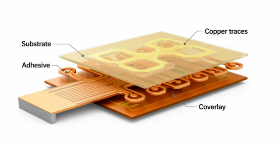
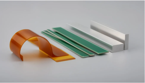
Flexible circuit board materials fall into several critical categories that work together to create a functioning flexible pcb. The primary material systems include dielectric substrate films, conductive traces (typically copper foil), adhesive layers for bonding, and protective coverlays that ensure reliable operation.
Material selection significantly impacts electrical performance through dielectric properties, signal attenuation characteristics, and impedance control capabilities. The mechanical properties determine bend radius limitations, fatigue resistance under dynamic applications, and dimensional stability across temperature changes.
Key properties that differentiate flexible PCB materials include thermal stability for withstand high temperatures, dielectric constant values affecting signal reflection, flexibility ratings for wearable devices and mobile applications, and chemical resistance for harsh environments. Cost considerations often drive material choices, particularly in high-volume consumer electronics where balancing performance against economic constraints is essential.
Market trends in 2024 show polyimide dominating approximately 70% of flexible PCB applications due to its excellent heat resistance and reliable signal transmission capabilities. However, specialized materials like liquid crystal polymer are gaining traction in high frequency circuits and 5G telecommunications, while cost-effective polyester maintains its position in price-sensitive consumer electronics applications.
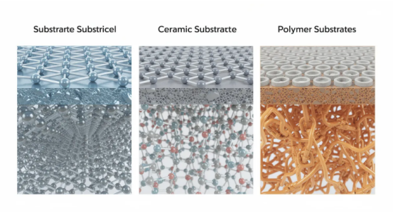
Substrate Materials for Flexible PCBs
The substrate material serves as the foundation layer providing both mechanical support and electrical insulation for the entire flexible circuit design. This dielectric material must balance sufficient mechanical strength to support conductive traces while maintaining the flexibility required for the intended application.
Substrate thickness typically ranges from 12.5 micrometers for ultra-thin applications to 125 micrometers for more robust designs requiring enhanced mechanical stability. The substrate choice directly affects achievable bend radius specifications, with thinner materials generally allowing tighter bending while thicker substrates provide better dimensional stability.
Manufacturing processes vary significantly based on substrate material selection. Some materials require specialized handling during component assembly, while others offer compatibility with standard printed circuit board manufacturing equipment. Industry standards such as IPC-2223 and IPC-6013 provide material qualification guidelines ensuring consistent performance across different suppliers and applications.
| Material | Thickness Range | Operating Temperature | Dielectric Constant | Key Applications |
|---|---|---|---|---|
| Polyimide | 12.5-125 μm | -55°C to +260°C | 3.4-3.6 | Aerospace, automotive, medical |
| Polyester (PET) | 23-125 μm | -40°C to +105°C | 3.2-3.8 | Consumer electronics, displays |
| LCP | 25-100 μm | -55°C to +280°C | 2.9-3.2 | High-frequency, telecommunications |
| PTFE | 25-254 μm | -200°C to +260°C | 2.0-2.1 | RF/microwave, satellite communications |
Polyimide (PI) - The Industry Standard
Polyimide represents the gold standard for flexible substrate materials, offering exceptional thermal performance with operating temperatures ranging from -55°C to +260°C. This temperature capability enables polyimide-based flexible circuitry to withstand high-temperature soldering processes and extreme temperatures encountered in automotive engine compartments and aerospace applications.
The coefficient of thermal expansion for polyimide averages 20 ppm/°C, providing excellent dimensional stability during temperature changes. This stability ensures maintaining reliable connections and prevents warpage that could compromise signal integrity or component assembly reliability.
Several types of polyimide films are available, including Kapton (DuPont), Apical (Kaneka), and UPILEX (Ube Industries), each optimized for specific applications. Kapton remains the most widely recognized, offering proven performance in space applications where reliable operation under temperature extremes and radiation exposure is critical.
Advanced polyimide formulations incorporate ceramic or glass fiber fillers to enhance thermal conductivity and mechanical strength. These filled polyimides provide improved thermal management for electronic components while maintaining the flexibility characteristics essential for flexible circuit design.
Cost considerations make polyimide more expensive than alternatives like polyester, but the superior performance justifies the investment in high performance applications. Aerospace, automotive safety systems, and medical devices consistently specify polyimide due to its proven reliability and consistent performance under demanding conditions.
Polyester (PET) - Cost-Effective Solution
Polyester substrate materials offer operating temperature limitations with maximum ratings typically between 105°C to 150°C, making them unsuitable for high-temperature soldering processes. This temperature constraint requires alternative assembly methods such as conductive epoxy bonding for electronic components.
The primary advantage of polyester lies in its cost benefits, typically providing 40-60% lower material costs compared to polyimide materials. This cost advantage makes polyester attractive for high-volume consumer electronics where budget constraints are significant and thermal demands remain modest.
Applications in consumer electronics include flexible connectors for displays, keyboard circuits, and LED lighting systems where operating temperatures remain below the material’s thermal limits. The manufacturing processes must accommodate polyester’s temperature sensitivity, often requiring specialized low-temperature assembly techniques.
Heat-induced shrinkage presents design considerations that engineers must address when specifying polyester substrates. The material can experience dimensional changes when exposed to elevated temperatures during manufacturing or operation, potentially affecting component placement accuracy and signal integrity.
Design guidelines for polyester-based flexible electronics emphasize careful thermal management and component placement strategies that minimize heat exposure to the substrate material while maintaining the required functionality for the intended application.
Liquid Crystal Polymer (LCP) - High-Performance Option
Liquid crystal polymer offers superior dimensional stability and exceptional moisture resistance properties that maintain consistent performance across varying environmental conditions. The low moisture absorption characteristics ensure that dielectric properties remain stable even in humid environments where other materials might experience performance degradation.
The dielectric constant for LCP typically ranges from 2.9 to 3.2, with extremely low loss tangent values that make it ideal for high frequency applications where signal loss must be minimized. These electrical characteristics enable reliable signal transmission in demanding applications such as 5G telecommunications infrastructure and high-speed data transmission systems.
Applications in 5G telecommunications take advantage of LCP’s stable electrical properties across the frequency spectrum, ensuring reliable signal transmission without significant signal attenuation. Medical imaging equipment also benefits from LCP’s consistent performance, particularly in applications requiring precise signal timing and minimal electromagnetic interference.
Processing requirements for LCP involve specialized manufacturing techniques that differ from standard polyimide processing. The material’s unique molecular structure requires careful temperature control during lamination and component assembly to achieve optimal adhesion and electrical performance.
Cost comparisons show LCP positioned between standard polyimide and premium materials like PTFE, making it an attractive option for applications requiring enhanced electrical performance without the premium cost associated with fluororesin materials.
Fluororesin Materials (PTFE and Derivatives)
PTFE and related fluororesin materials provide ultra-low dielectric loss characteristics that make them essential for microwave and RF applications where signal integrity cannot be compromised. The dielectric constant typically ranges from 2.0 to 2.1, representing the lowest values available in flexible substrate materials.
Temperature stability extends from -200°C to +260°C, covering the broadest operating range of any flexible substrate material. This exceptional thermal performance enables reliable operation in extreme environments while maintaining consistent electrical characteristics across the entire temperature spectrum.
Chemical inertness provides resistance to harsh environments including exposure to aggressive chemicals, solvents, and cleaning agents that might degrade other substrate materials. This chemical resistance makes PTFE suitable for industrial sensors and medical devices where exposure to sterilization chemicals is required.
Applications in automotive radar systems, ADAS (Advanced Driver Assistance Systems), and antenna designs leverage PTFE’s superior electrical performance for ensuring reliable signal transmission in safety-critical systems. The material’s stable electrical properties enable precise radar measurements and reliable communication links essential for autonomous vehicle functionality.
Processing challenges include adhesion considerations since PTFE’s chemical inertness also makes it difficult to bond with adhesives and other materials. Specialized surface treatments and adhesive systems have been developed to address these bonding challenges while preserving the material’s electrical advantages.
Conductor Materials and Copper Foil Types
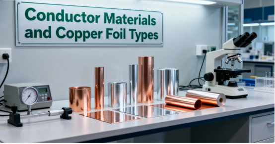
Copper foil selection criteria for flexible PCB applications focus on achieving optimal balance between electrical conductivity, mechanical flexibility, and cost considerations. The conductor material must maintain low resistance while withstanding repeated flexing without fatigue failure or signal degradation.
Thickness options for copper foil range from 9 μm (¼ oz) to 105 μm (3 oz), with thinner foils providing enhanced flexibility at the expense of current-carrying capacity. Thicker copper layers support higher current requirements but reduce the overall flexibility of the flexible circuit.
Surface treatment options include organic solderability preservatives (OSP), electroless nickel immersion gold (ENIG), and hard gold plating, each optimizing different performance characteristics. These treatments enhance adhesion, improve signal integrity, and provide corrosion protection while maintaining compatibility with various assembly processes.
Cost implications vary significantly between different copper foil types, with rolled annealed copper commanding premium pricing due to its superior flexibility characteristics. Standard electrodeposited copper provides cost advantages for applications where extreme flexibility is not required.
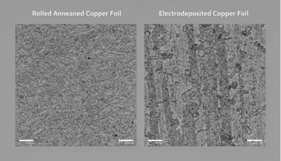
Rolled Annealed (RA) Copper Foil
The manufacturing process for rolled annealed copper creates a unique grain structure that provides exceptional flexibility and fatigue resistance compared to electrodeposited alternatives. The rolling process aligns copper grains in directions that enhance ductility and resistance to crack propagation during repeated bending cycles.
Superior bendability characteristics make RA copper essential for dynamic applications such as wearable devices, camera modules, and robotic systems where continuous flexing is expected during normal operation. The material can withstand thousands of bend cycles without developing fatigue cracks that would compromise electrical performance.
Lower insertion loss for high frequency circuits results from the smoother surface characteristics and optimized grain structure of rolled annealed copper. This electrical advantage becomes particularly important in high speed applications where signal attenuation must be minimized to maintain data integrity.
Applications requiring repeated flexing include automotive wiring harnesses, medical device sensors, and consumer electronics with moving components. The enhanced fatigue resistance of RA copper ensures reliable operation throughout the product’s expected lifetime, even under demanding mechanical conditions.
Comparison with standard electrodeposited copper shows RA copper provides 3-5 times greater ductility and significantly improved resistance to mechanical stress. This performance advantage justifies the higher cost for applications where mechanical reliability is critical.
Electrolytic Deposition (ED) Copper Foil
Higher purity levels exceeding 99.8% characterize electrodeposited copper foil, providing excellent electrical conductivity and consistent electrical properties across the entire foil surface. The electroplating process enables precise control of thickness uniformity and surface characteristics.
Smoother surface finishes achieved through electrodeposition processes reduce signal loss in high frequency applications by minimizing surface roughness that can cause signal reflection and attenuation. This surface quality advantage makes ED copper suitable for controlled impedance applications where signal integrity is paramount.
Limitations in flexibility and mechanical stress tolerance restrict ED copper to static flexible PCB applications or designs with minimal bending requirements. The material’s grain structure, while providing excellent electrical properties, lacks the ductility needed for dynamic applications.
Cost advantages make electrodeposited copper attractive for high-volume applications where flexibility requirements are modest and cost optimization is prioritized. The manufacturing process scales efficiently for large production volumes, reducing raw material costs compared to specialized copper types.
When to choose ED over RA copper depends on application requirements, with ED copper preferred for static applications requiring excellent electrical performance at competitive costs, while RA copper becomes essential when mechanical flexibility and fatigue resistance are critical design requirements.
Adhesive Materials and Bonding Systems
Adhesive materials play crucial roles in flexible PCB construction by bonding copper conductors to substrate materials while maintaining the overall flexibility and reliability of the circuit assembly. The adhesive system must accommodate thermal cycling, mechanical stress, and environmental exposure while preserving electrical insulation properties.
Types of adhesives include acrylic formulations offering good flexibility and moderate temperature resistance, epoxy systems providing superior bond strength and chemical resistance, and modified polyimide adhesives combining thermal stability with mechanical compliance. Each adhesive type offers distinct advantages for specific application requirements.
Adhesiveless constructions eliminate the adhesive layer entirely by directly bonding copper to substrate materials through specialized manufacturing processes. This approach reduces overall thickness, improves flexibility, and enhances high frequency performance by eliminating a potential source of dielectric loss and impedance mismatches.
Temperature ratings for adhesive systems range from 85°C for standard acrylic formulations to over 200°C for modified polyimide adhesives, enabling selection based on the expected operating environment and assembly process requirements. Thermal cycling performance ensures reliable bonding throughout repeated temperature excursions.
The impact on overall flexible PCB thickness becomes significant when multiple adhesive layers are required for complex constructions. Adhesiveless systems can reduce total thickness by 25-40%, enabling more compact designs and improved flexibility characteristics essential for space constrained applications.
Reinforcement and Stiffener Materials
Stiffeners serve essential purposes in flexible circuit design by providing localized rigidity for connector attachment points, component mounting areas, and regions requiring enhanced mechanical stability. These reinforcement materials enable reliable component assembly while maintaining flexibility in other circuit areas.
Material options for stiffeners include polyimide film matching the base substrate material for thermal compatibility, FR4 fiberglass providing maximum rigidity for heavy components, stainless steel offering electromagnetic shielding properties, and aluminum delivering excellent thermal conductivity for thermal management applications.
Thickness considerations range from 0.1mm for light reinforcement to 1.6mm for heavy-duty component mounting applications. The stiffener thickness must balance mechanical support requirements against overall assembly thickness constraints and flexibility preservation in adjacent areas.
Installation methods include adhesive bonding using pressure-sensitive or thermally activated adhesives, and mechanical attachment through rivets or other fasteners for high-stress applications. The installation method affects both manufacturing complexity and long-term reliability under mechanical stress.
Design guidelines emphasize proper stiffener placement to avoid stress concentration points that could lead to failure under repeated flexing. Gradual transitions between rigid and flexible areas, appropriate edge treatment, and careful consideration of thermal expansion differences ensure reliable operation across the expected operating conditions.
Material Selection Criteria and Trade-offs
Performance requirements matrices help engineers evaluate thermal capabilities, electrical characteristics, mechanical properties, and environmental resistance for specific applications. This systematic approach ensures optimal material selection by weighing multiple factors simultaneously rather than optimizing for a single parameter.
Thermal requirements encompass operating temperature range, thermal cycling endurance, and thermal expansion compatibility with other assembly materials. Applications in automotive engine compartments require materials capable of withstanding continuous exposure to extreme temperatures while maintaining reliable electrical connections.
Electrical performance criteria include dielectric constant stability, loss tangent minimization for signal integrity, impedance control requirements, and electromagnetic interference shielding needs. High frequency transmission applications prioritize low dielectric constant and loss tangent values over other material properties.
Mechanical considerations evaluate bend radius requirements, fatigue resistance for dynamic applications, tensile strength for assembly processes, and vibration tolerance for industrial applications. Wearable devices require materials that maintain electrical performance through thousands of bending cycles.
Cost analysis comparing material options must consider both raw material costs and manufacturing process implications. Premium materials like LCP or PTFE may justify their higher costs through improved performance that enables system-level cost reductions or enhanced functionality.
Manufacturing compatibility ensures selected materials work with available production equipment and assembly processes. Some advanced materials require specialized handling or modified processing parameters that could impact production schedules or yield rates.
Reliability testing standards including IPC-2223 for flexible PCB design guidelines and IPC-6013 for qualification and performance specifications provide frameworks for material evaluation and acceptance criteria. These standards ensure consistent performance across different suppliers and manufacturing locations.
Future trends in material development focus on 5G telecommunications requiring ultra-low loss materials, automotive applications demanding higher temperature ratings, and wearable applications needing improved biocompatibility and washability characteristics.
Application-Specific Material Recommendations

Consumer electronics applications balance cost constraints against performance requirements for smartphones, tablets, and wearable technology. Polyester substrates often provide sufficient performance for display connections and simple circuits, while polyimide becomes necessary for processors and power management circuits requiring higher thermal capability.
Smartphone applications typically specify polyimide for main board connections due to thermal demands from processors and power management circuits, while display connectors may use cost-effective polyester materials. Camera module connections require rolled annealed copper for superior flexibility during focus and stabilization movements.
Tablet designs emphasize thin profile requirements that favor adhesiveless constructions and thinner substrate materials. The larger form factor allows for more gradual bend radii, potentially enabling the use of less expensive materials while maintaining reliability.
Automotive applications face extreme temperatures, vibration, chemical exposure, and safety-critical reliability requirements that typically mandate polyimide substrates with specialized additives for enhanced performance. Engine compartment applications require materials rated for continuous operation above 150°C with resistance to automotive fluids and cleaning chemicals.
Safety system applications including airbag sensors, ABS controllers, and advanced driver assistance systems specify polyimide or LCP substrates due to their proven reliability under extreme conditions. These applications cannot tolerate material failures that could compromise vehicle safety.
Medical devices require biocompatible materials and sterilization compatibility for implantable applications, while external medical equipment prioritizes chemical resistance for cleaning and disinfection procedures. Polyimide substrates often receive special surface treatments to enhance biocompatibility.
Sterilization compatibility encompasses gamma radiation, ethylene oxide gas, and steam autoclave processes that can degrade some substrate materials. Medical device designers must verify material compatibility with required sterilization methods throughout the product’s service life.
Aerospace and defense applications specify materials meeting MIL-STD specifications for temperature extremes, radiation resistance, and outgassing characteristics required for space applications. These demanding environments require the highest performance materials regardless of cost considerations.
Space qualification involves extensive testing for vacuum outgassing, radiation effects, and thermal cycling across extreme temperature ranges. Only proven materials with extensive flight heritage typically gain acceptance for critical space applications.
Industrial sensors must withstand chemical exposure, vibration, and temperature cycling while maintaining accurate measurements over extended periods. Material selection emphasizes chemical resistance and dimensional stability to ensure measurement accuracy throughout the sensor’s operational life.
Vibration tolerance becomes critical for industrial applications where mechanical shock and continuous vibration could cause material fatigue or delamination. Specialized adhesive systems and reinforced constructions provide enhanced durability for these demanding environments.
The electronics industry continues evolving toward more demanding applications that push material performance limits. Global demand for high performance flexible circuits drives ongoing material development efforts focused on enhanced thermal performance, lower signal loss, and improved reliability across diverse applications from mobile devices to demanding environments in aerospace and automotive systems.
Understanding the different materials of flexible circuit boards enables engineers to make informed decisions that optimize performance while managing costs across the product lifecycle. Whether designing flexible circuits for consumer electronics or mission-critical applications, proper material selection ensures reliable operation while meeting the specific requirements of each unique application.
FAQs
Q: What are the main types of FPC core substrates?
A: There are four primary categories: Polyimide (PI, high-temperature resistant), Polyester (PET, low-cost), Liquid Crystal Polymer (LCP, suitable for high-frequency applications), and Polytetrafluoroethylene (PTFE, ultra-low dielectric loss).
Q: What is the key difference between PI and PET substrates?
A: PI withstands high temperatures (-55℃ to 260℃), offers excellent performance but is more expensive, making it suitable for aerospace and medical applications. PET has a lower temperature tolerance (-40℃ to 105℃), is more cost-effective, and is commonly used in consumer electronics.
Q: Which substrate is preferred for high-frequency/5G scenarios?
A: Liquid Crystal Polymer (LCP) is the preferred choice due to its low dielectric constant (2.9–3.2) and minimal signal loss, which align well with high-frequency transmission requirements.
Q: What are the types of copper foil used in FPCs, and how are they selected?
A: Copper foils are categorized into Rolled Annealed (RA, offering good flexibility for dynamic bending applications) and Electro-Deposited (ED, providing excellent conductivity at a lower cost, suitable for static applications). Selection is based on bending requirements.
Q: What are the advantages of adhesive-less FPC structures?
A: Adhesive-less designs reduce thickness by 25%–40%, enhance flexibility, lower dielectric loss, and optimize high-frequency performance.
Q: What is the purpose of stiffeners in FPCs?
A: Stiffeners provide localized rigid support for connectors and component areas to ensure reliable assembly, while preserving flexibility in other sections of the circuit.
Q: What are the key requirements for substrate selection in automotive/aerospace applications?
A: Priority is given to temperature resistance (e.g., PI withstands 260℃), fatigue resistance, and chemical corrosion resistance, in compliance with industry reliability standards such as IPC-6013.
Q: What key factors must be balanced during material selection?
A: Critical considerations include thermal performance (temperature resistance), electrical properties (dielectric constant), mechanical behavior (bend radius), cost, and manufacturing compatibility.
Author: Jack Wang

