Top 10 Common Components on a PCBA and Their Roles in Electronics
A Printed Circuit Board Assembly (PCBA) is the heart of modern electronics, transforming raw circuit designs into functional systems. It refers to a complete circuit board populated with electronic components such as resistors, capacitors, and integrated circuits. These components are carefully soldered onto a Printed Circuit Board (PCB) to enable the board to perform its intended electrical functions.
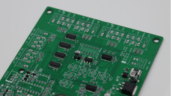
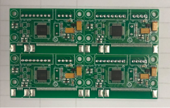
The distinction between PCB and PCBA is simple but crucial. A PCB is an unassembled board made of insulating material and copper traces—it provides the structure and pathways for electrical signals. Once components are mounted and soldered, the same board becomes a PCBA, capable of processing signals, distributing power, and performing control tasks. For example, the motherboard inside a computer or smartphone is a PCBA, not just a bare PCB.
Each component on a PCBA acts as a functional building block within an electronic circuit. Resistors manage current, capacitors stabilize voltage, transistors amplify signals, and ICs handle complex logic operations. When combined, they form the intelligent systems that power devices across industries—from communication equipment and medical instruments to automotive electronics and industrial controllers.
By mastering the roles of key components, engineers and product designers can achieve higher circuit efficiency, better reliability, and smoother production processes—ensuring performance that lasts.
Understanding PCBA and Its Importance
What Is a PCBA?
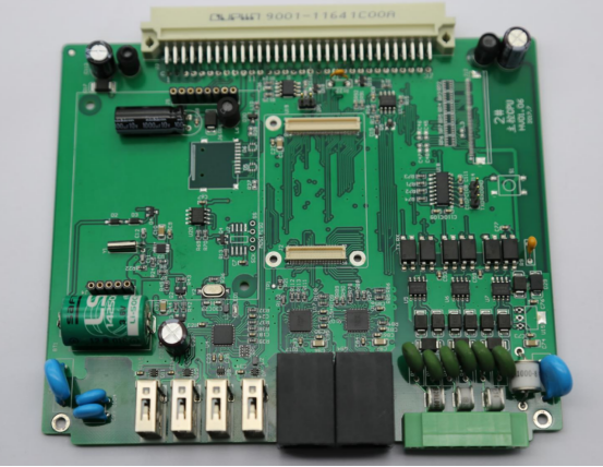
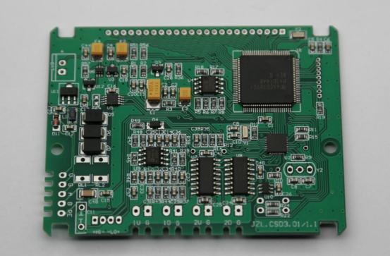
A Printed Circuit Board Assembly (PCBA) is a fully functional electronic board that integrates both the physical PCB structure and the mounted electronic components. In essence, a PCBA = PCB + components. It serves as the operational core of electronic products, allowing signals and power to move seamlessly between different parts of a system.
The PCBA manufacturing process involves four main stages:
1. Design – Engineers create the circuit layout and define component placement and signal routing.
2. Fabrication – The bare PCB is produced using copper-clad laminates and insulating materials.
3. Assembly – Electronic components such as resistors, capacitors, and ICs are soldered onto the board using SMT (Surface Mount Technology) or through-hole methods.
4. Testing – Each assembled board undergoes electrical and functional testing to verify performance and detect defects before mass production.
By completing these steps, a bare circuit board becomes a reliable, ready-to-use PCBA, capable of powering everything from smart home devices to advanced communication systems.
Why Components Matter in PCBA Performance
Every component on a PCBA directly influences how the board performs. The choice and quality of components determine critical factors such as signal integrity, power distribution, and overall reliability.
For instance, capacitor selection plays a key role in maintaining signal stability. Using high-frequency ceramic capacitors can reduce electrical noise and filter out voltage fluctuations, ensuring cleaner data transmission. Similarly, resistors regulate the current flow within circuits—choosing incorrect resistance values can lead to overheating, signal distortion, or inefficient power usage.
Other examples include inductors that stabilize current in power converters, and diodes that prevent reverse current from damaging sensitive chips. When these components are carefully matched and placed, the PCBA can operate with greater efficiency, thermal balance, and signal accuracy.
In short, component selection is not just a design detail—it defines the reliability and performance of the entire electronic system. High-quality components, proper layout, and precise soldering together ensure that the PCBA delivers stable, long-term functionality across a wide range of operating conditions.
Top 10 Common Components on a PCBA
1. Resistors
A resistor is an electronic component that controls current flow and divides voltage in a circuit. By providing electrical resistance, it limits how much current passes through specific paths.
Example: In a microcontroller circuit, a pull-up resistor ensures that an input pin reads a stable logic level when no signal is present.
Comparison:
Fixed resistors have a constant resistance value and are used for stable voltage control.
Variable resistors or potentiometers allow manual adjustment of resistance, often used for tuning or calibration.
Role in circuits: Resistors protect sensitive components, set biasing levels, and form voltage dividers for analog measurements.
2. Capacitors
A capacitor temporarily stores and releases electrical energy. It consists of two conductive plates separated by an insulating material called a dielectric.
Types:
Ceramic capacitors for high-frequency filtering.
Electrolytic capacitors for bulk energy storage.
Tantalum capacitors for stable performance in compact circuits.
Applications: Used for noise filtering, timing, and power smoothing—for example, stabilizing voltage in power supply lines to prevent sudden drops or spikes.
3. Inductors
An inductor stores energy in a magnetic field when current passes through it. It resists changes in current, making it ideal for power and signal conditioning.
Common uses: Found in power supplies, RF circuits, and filters where energy transfer and noise suppression are critical.
Example: In a DC-DC converter, inductors smooth out current flow and regulate output voltage during switching cycles.
4. Diodes
A diode allows current to flow in one direction only, blocking reverse current that could damage components.
Variants:
Zener diodes for voltage regulation.
Schottky diodes for fast switching and low forward voltage.
Light-emitting diodes (LEDs) for illumination and indication.
Applications: Used for rectification, signal demodulation, and reverse-polarity protection in power circuits.
5. Transistors
A transistor functions as both a switch and an amplifier in electronic circuits. It controls large electrical currents using a smaller input signal.
Types:
l BJT (Bipolar Junction Transistor) – controls current with current.
l MOSFET (Metal-Oxide-Semiconductor Field-Effect Transistor) – controls current with voltage.
Example: In power regulation circuits, MOSFETs efficiently switch high currents in converters or motor drivers.
Step-by-step: How amplification works
1. A small input signal enters the transistor’s base or gate.
2. The transistor modulates a larger current through its collector or drain.
3. The output signal mirrors the input but with higher amplitude—achieving signal amplification.
6. Integrated Circuits (ICs)
An Integrated Circuit (IC) is a miniaturized electronic circuit embedded on a semiconductor chip. It can contain thousands or millions of transistors, resistors, and capacitors.
Categories:
l Analog ICs handle continuous signals (e.g., operational amplifiers).
l Digital ICs process binary data (e.g., microcontrollers, logic gates).
l Mixed-signal ICs combine both functions for real-world signal processing.
Examples: MCUs, op-amps, and memory chips form the control and computation core of most PCBAs, enabling complex operations in compact designs.
7. Crystals and Oscillators
Crystals and oscillators generate clock signals that synchronize the timing of digital circuits.
Comparison:
A quartz crystal vibrates at a fixed frequency when voltage is applied, offering high precision.
A MEMS oscillator uses micro-mechanical structures for stable, compact timing solutions.
Example: A microprocessor relies on a crystal oscillator to maintain consistent timing for data processing and communication. Without it, digital systems lose synchronization and stability.
8. Connectors
A connector provides electrical and mechanical links between a PCBA and external devices or other boards. It allows detachable or modular connections without soldering.
Types:
Pin headers and sockets for board-to-board links.
USB connectors for data and power interfaces.
FPC (Flexible Printed Cable) and edge connectors for compact designs.
Design considerations: Engineers evaluate contact resistance, current capacity, and mating cycles to ensure reliability in repeated use.
9. Switches and Relays
Switches and relays are components that control electrical signals or power flow.
Comparison:
Manual switches require physical action (e.g., push buttons).
Solid-state relays or electromechanical relays perform the same task electronically or magnetically.
Applications: Used for power control, circuit isolation, and automation systems—for example, turning on motors or activating safety interlocks.
10. LEDs and Display Modules
LEDs (Light-Emitting Diodes) and display modules provide visual indicators or data display functions on a PCBA.
Examples:
Status LEDs indicate power or signal activity.
Seven-segment displays show numerical data.
LCD or OLED modules display text and graphics in embedded systems.
Integration: LED brightness and display contrast are managed by driver circuits or controller ICs, ensuring consistent visibility across varying power levels.
Summary Insight
Each of these ten components plays a unique yet interdependent role in electronic design. Together, they enable a PCBA to manage power, process signals, communicate data, and provide user interaction—transforming a simple circuit board into a functional, intelligent electronic system.
How These Components Work Together on a PCBA
Signal Path Example
A PCBA operates as an integrated system where electrical signals flow through defined paths—from input to processing to output.
Step-by-step signal flow:
1. Input: A sensor or external module detects a physical condition such as temperature, pressure, or motion.
2. Processing: The input signal passes through conditioning components like resistors and capacitors, then into an Integrated Circuit (IC)—often a microcontroller or amplifier—that interprets or modifies the data.
3. Output: The processed signal activates another component, such as a transistor driving an LED or motor.
Example: In an environmental monitoring device, a temperature sensor sends analog data to an IC. The IC converts the data to a digital signal, a transistor amplifies the output current, and an LED lights up to indicate that the measured temperature exceeds a threshold.
This coordinated interaction illustrates how different PCBA components communicate seamlessly to complete a circuit function.
Power Management Overview
Stable power distribution is essential for every PCBA. Components like resistors, capacitors, and inductors play complementary roles in maintaining voltage stability and current consistency.
Resistors regulate current and prevent overloading of sensitive components.
Capacitors smooth voltage fluctuations by storing and releasing charge as needed.
Inductors filter out electrical noise and maintain steady current in power lines.
Together, these components form power regulation networks that ensure circuits operate within safe electrical limits.
Importance of layout and grounding:
Proper PCB layout and grounding design are just as critical as component choice. A well-designed ground plane minimizes signal interference and voltage drops, while short, wide power traces reduce resistance and heat buildup. Effective layout design leads to clean power delivery and reliable signal performance across the entire assembly.
Control and Communication
In modern electronics, communication between components and external devices is managed through control logic and data interfaces. Integrated Circuits (ICs) and connectors serve as the main enablers of this interaction.
Role of ICs: Microcontrollers, processors, or communication chips manage data exchange via protocols such as I²C, SPI, and UART. These interfaces allow fast, synchronized communication between sensors, memory, and other peripherals.
Role of connectors: Connectors establish physical and electrical links between the PCBA and external modules—such as displays, communication ports, or power sources.
Example: A microcontroller (MCU) sends data through the SPI interface to an external display module via a board connector. The connector transmits signals and power simultaneously, enabling the display to show processed results in real time.
By integrating precise control through ICs and reliable connectivity via connectors, a PCBA achieves both intelligent operation and system-level communication efficiency.
Factors Affecting Component Selection
Selecting the right components for a Printed Circuit Board Assembly (PCBA) is one of the most critical steps in ensuring performance, reliability, and manufacturability. Each decision—whether electrical, environmental, or economic—directly affects how well a circuit functions in real-world conditions.
Electrical Requirements
Every component must meet the electrical specifications of the circuit where it operates. The three main parameters to consider are voltage, current, and frequency.
Voltage rating defines how much potential difference a component can safely handle. Using a capacitor or transistor below its rated voltage may lead to breakdown or permanent damage.
Current rating indicates the maximum current a part can carry without overheating or degrading. Exceeding this value can cause failures or affect nearby components.
Frequency response determines how a component behaves at different signal speeds. For example, a high-frequency circuit requires low-loss capacitors and short signal paths to preserve signal integrity.
Tolerance and rating accuracy also influence performance. For instance, a resistor with a ±1% tolerance maintains more consistent current control than one with ±5%. Choosing components with the correct electrical margins ensures both functional stability and design safety under variable operating conditions.
Environmental and Reliability Factors
A PCBA must perform reliably within its intended environment. Factors such as temperature, vibration, and humidity can significantly affect component behavior and lifespan.
Temperature range: Components used in industrial or automotive electronics must tolerate extreme heat and cold, typically from –40°C to +125°C. Consumer-grade parts, by contrast, may only operate between 0°C and +70°C.
Vibration resistance: In vehicles or aerospace applications, solder joints and components face continuous mechanical stress, requiring reinforced mounting or conformal coating.
Humidity protection: Moisture can cause corrosion or leakage currents; therefore, protective coatings or sealed components are used in humid environments.
Example: In automotive PCBAs, manufacturers select high-reliability capacitors, sealed connectors, and automotive-grade ICs certified under AEC-Q100 standards. In consumer electronics, designers may prioritize compactness and cost-efficiency instead, as environmental demands are lower.
Understanding environmental limits ensures that component selection aligns with the real-world conditions of the final product.
Cost and Sourcing
Balancing performance, cost, and availability is essential for practical PCBA design. While high-spec components may offer superior performance, they often increase overall production cost.
Performance vs. cost trade-off: Designers must decide when premium materials—such as low-loss laminates or precision resistors—are justified by the product’s performance goals.
Availability and obsolescence: Reliable sourcing is as important as technical fit. A design dependent on obsolete or hard-to-find components can cause production delays and long-term maintenance issues.
To mitigate risks, many companies maintain approved vendor lists (AVL) and perform lifecycle management for components. Selecting parts with stable supply chains and multiple sourcing options ensures smoother production scaling and supply continuity.
In summary, electrical accuracy, environmental robustness, and cost-effective sourcing together define the quality and longevity of a PCBA. Effective component selection requires not only technical insight but also a strategic understanding of market and manufacturing realities.
Conclusion
A deep understanding of PCBA components is essential for designing electronics that are both reliable and efficient. Each element—from resistors and capacitors to ICs and connectors—plays a distinct role in signal processing, power management, and overall system functionality. Recognizing how these components interact allows engineers and designers to optimize circuit performance, reduce failure rates, and enhance long-term durability.
Proper component selection ensures that circuits operate within safe voltage, current, and frequency limits, maintain stable power distribution, and perform reliably under environmental stresses such as temperature changes or vibration. For example, choosing automotive-grade capacitors and robust connectors in harsh environments prevents early failures, while selecting the right ICs and transistors ensures accurate signal amplification and timing.
Collaborating with experienced PCB manufacturers, such as PCBMASTER, further improves the quality and manufacturability of assemblies. Expert partners provide guidance on component sourcing, layout optimization, and assembly best practices, helping engineers bring designs from concept to production with confidence. Leveraging such expertise ensures that PCBAs are not only technically sound but also scalable, cost-effective, and ready for real-world applications.
In short, mastering component selection and working with seasoned manufacturers is key to creating high-performance, durable, and efficient PCBA solutions that meet modern electronic design demands.
FAQs
1. What is the difference between active and passive components on a PCBA?
Active components can amplify, switch, or control electrical signals and usually require external power.
Examples: Transistors, Integrated Circuits (ICs), Microcontrollers, LEDs.
Passive components do not generate or amplify energy; they only store, dissipate, or regulate it.
Examples: Resistors, Capacitors, Inductors, Connectors.
Summary: Active components control circuit behavior; passive components support or modify signals.
2. How can I visually identify components on a PCBA?
Resistors: Small rectangular or cylindrical parts with color bands or printed codes.
Capacitors: Cylindrical (electrolytic) or rectangular (ceramic/MLCC).
ICs: Black rectangular chips with multiple pins.
LEDs: Small colored or transparent diodes.
Surface-mount vs. Through-hole: SMD components sit flat on pads; through-hole components have leads inserted into holes.
Tip: Confirm identification using PCB schematics or component datasheets.
3. Why are some components surface-mounted while others are through-hole?
Surface-Mount Technology (SMT):
Components are soldered directly on PCB pads.
Benefits: Smaller size, higher component density, automated assembly.
Common use: Compact consumer electronics and high-density PCBs.
Through-Hole Technology (THT):
Components have leads inserted into PCB holes and soldered.
Benefits: Stronger mechanical support, higher current capacity.
Common use: Connectors, large capacitors, or high-stress applications.
Decision factors: Mechanical strength, current requirements, board space, and assembly cost.
4. What causes component failure on a PCBA?
Electrical stress: Overvoltage, overcurrent, or short circuits.
Thermal stress: Excess heat due to poor design or high-power operation.
Mechanical stress: Vibration, bending, or impact.
Environmental factors: Moisture, corrosion, or dust contamination.
Manufacturing defects: Poor solder joints, misaligned parts, or damaged traces.
Prevention: Use high-quality components, proper assembly practices, and environmental protection.
5. How can I choose the right supplier for PCBA components?
Reliability: Supplier must provide certified, tested components.
Availability: Consistent stock and multiple sourcing options to avoid production delays.
Compliance: Components should meet standards like RoHS or AEC-Q100 for automotive electronics.
Technical support: Access to datasheets, application notes, and selection guidance.
Cost-effectiveness: Balance performance, lead times, and price.
Tip: Partnering with experienced PCB manufacturers, such as PCBMASTER, ensures high-quality assemblies and supply chain stability.