


Why PCB Circuit Rework Unacceptable Can Hinder Your Project Success
Introduction
In the world of electronics manufacturing, the Printed Circuit Board (PCB) is the undeniable “skeleton” and “circulatory system,” carrying and interconnecting all electronic components. Within the processes of PCB fabrication and assembly, the term “rework” was once a familiar and often unavoidable step for many engineers and factory managers. A board has an issue? Take it to the rework station, apply some hot air, replace a few components, and the problem seems solved.
However, we must present a viewpoint that is gaining significant traction in today’s landscape of high-end, precision, and high-reliability products: Circuit Rework is Unacceptable. While rework and repair are generally considered acceptable industry standard practices, some companies and customers refuse to accept boards that have undergone rework, especially for military products and other applications where reliability is critical.
This might sound absolute, even unreasonable. But allow me to explain why this concept is shifting from an “ideal” to a “necessity.”
Understanding PCB Rework

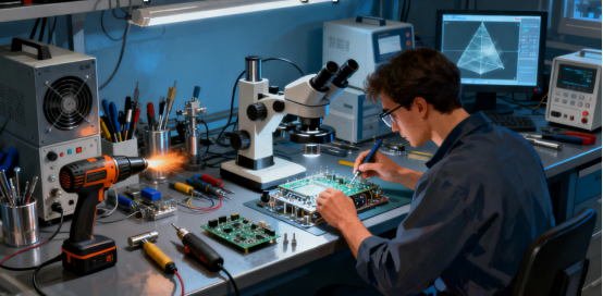
PCB rework is an essential process within the electronics manufacturing industry, designed to repair, modify, or upgrade circuit boards to ensure they meet stringent specifications and industry standards. At the forefront of this field, the Circuit Technology Center and other leaders in circuit board assemblies stress that effective rework is not just about fixing defects—it’s about maintaining the highest levels of product reliability and compliance throughout the lifecycle of a circuit board.
Rework operators play a pivotal role in this process. Their expertise, combined with strict adherence to IPC guidelines, applicable drawings, and acceptance criteria, ensures that every repaired board aligns with both industry standards and customer requirements. The rework process typically involves the careful use of solder paste, soldering irons, and other specialized tools to remove and replace components, repair solder joints, and apply solder mask. Each step must be executed with precision to avoid introducing new defects or compromising the integrity of the PCB.
Process control is critical in high-volume PCB manufacturing environments, where efficiency must be balanced with uncompromising quality. Techniques such as thermal profiling help prevent damage from high temperatures during rework, safeguarding the long-term reliability of the circuit board. Advanced testing methods, including x-ray inspection and high-frequency testing, are often employed to verify the quality of solder joints and detect hidden defects that could affect performance, especially in complex or densely populated electronic assemblies.
Customer requirements are central to determining the acceptability of reworked boards. Some customers, particularly in sectors like aerospace, military, or medical devices—where a pacemaker implanted inside a patient or a flight-critical system is at stake—demand full compliance with rigorous specifications and may require additional inspection or documentation. In these cases, rework operators must be thoroughly trained and certified, ensuring they can deliver reliable, high-quality results even under extreme conditions.
Beyond simple repairs, PCB rework can also involve the modification or upgrade of existing circuit boards to meet new specifications or extend product life. This approach can be cost-effective for companies seeking to adapt to evolving technology or customer needs without the expense of complete redesigns. However, any modification must be performed in accordance with IPC standards and other industry regulations to ensure continued product reliability and safety.
In summary, PCB rework is a complex, highly technical process that demands attention to detail, specialized equipment, and a deep understanding of both the technology and the applicable standards. By following best practices in process control, leveraging advanced tools, and maintaining open communication with customers, companies can ensure that their repaired boards meet the highest standards of quality and reliability. Whether assembling products for high-frequency applications, high-volume production, or mission-critical environments, the quality of the rework process is fundamental to the success and reputation of any electronics manufacturing operation.
The "Misleading Perception" and "Harsh Reality" of Rework
Internal Damage to the PCB Itself
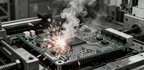
·Thermal Stress Damage: The core of rework involves localized heating. No matter how advanced the technology, the thermal shock from a hot air gun or rework station on the solder pads and surrounding components is severe. A PCB is a laminate of different materials (epoxy resin, fiberglass, copper) with different coefficients of thermal expansion. Repeated, uneven heating causes:
·Pad Lifting: The copper foil separates from the substrate, creating a permanent open circuit.
·PCB Delamination: Microscopic gaps form between the internal layers, leading to reduced insulation resistance, impaired high-frequency signal integrity, and potential catastrophic failure later as moisture seeps in.
·Barrel Cracking: The plated through-holes, especially microvias in High-Density Interconnect (HDI) boards, are particularly vulnerable to thermal stress.
Reworking surface mount components can be especially risky due to the sensitivity of the material and the need to replicate original thermal profiles to avoid damaging soldered joints.
The “Invisible” Reliability Killers
·Degraded Solder Joint Quality: Re-soldering can rarely match the precise temperature control and uniform heating of the original reflow oven. This easily leads to cold solder joints or intermittent connections. Replacement of components during rework rarely achieves the same quality as the original soldered connections, and improper thermal profiles can lead to hidden defects. These defects might not be caught during initial testing but can manifest later under user conditions—like vibration or temperature cycles—causing intermittent failures.
·Damage to Adjacent Components: Heat inevitably affects nearby healthy components. Temperature-sensitive components, like Multi-Layer Ceramic Capacitors (MLCCs), are particularly at risk. Thermal stress can cause internal micro-cracks, leading to capacitance drift, short circuits, and a drastically reduced lifespan.
·Chemical Contamination: Flux used during rework, if not thoroughly cleaned, can leave residues that corrode circuitry over time, leading to ionic migration and potential short circuits.
Even advanced test methods and tests may not detect all issues caused by reworking, such as micro-cracks in the material.
For example, improper rework of a surface mount component may result in a latent failure: the board passes all initial tests, but a micro-crack in the soldered joint or material leads to failure in the field under thermal cycling.
Why We Assert: "Circuit Rework is Unacceptable"
This statement is not made lightly. While rework may seem practical and acceptable in some cases, it is often not aligned with industry standard practices for high-reliability products. It is driven by four major trends in modern electronics.
·The Evolution of Cost Perception
As electronics have become more complex, the costs associated with rework have increased significantly. These costs include not only direct expenses such as labor and materials, but also hidden costs like increased rework time, potential damage to components, scrap, and the impact on the reliability of reassembled boards. For example, in a high-reliability manufacturing environment, the costs of rework can quickly outweigh any perceived savings, especially when factoring in the risk of latent defects and additional quality assurance measures.
·The Demand for Ultra-High Reliability
In sectors where ultra-high reliability is required, such as aerospace and defense, boards must be manufactured to meet the highest industry standards. This makes rework less acceptable, as even minor deviations from original manufacturing processes can compromise reliability and compliance.
Trend 1: Miniaturization and High-Density Integration
Today’s electronics, from smartphones to wearables, feature increasingly smaller PCBs with component pitches measured in microns. Miniaturized surface mount components require careful selection of material and precise control of thermal profiles during any rework attempt to avoid damage. At this scale, any rework attempt is like performing “surgery” on a delicate miniature engraving—the success rate is low, and the risk of “collateral damage” is high. A trace width might be finer than a human hair; a blast of hot air could easily bridge several adjacent traces.
Trend 2: The Demand for Ultra-High Reliability
Our society increasingly depends on highly reliable electronic systems: autonomous driving systems in cars, life-support medical equipment, data center servers, aerospace avionics… Any failure in these fields can have catastrophic consequences. In these contexts, a reworked PCB with “internal damage” is a time bomb with an unknown fuse. For military products, strict adherence to pcb design standards and comprehensive test procedures is essential to ensure reliability and performance in demanding environments, making rework even less acceptable. Reliability is not achieved through repair; it is built-in during manufacturing.
Trend 3: The Evolution of Cost Perception
Many managers still focus only on the saved cost of a single board’s components. They overlook:
·Time Cost: Rework is a manual process, extremely time-consuming, and slows down the entire production cycle.
·Quality Cost: This includes potential field returns, high failure rates during the warranty period, and damage to brand reputation.
·Inspection Cost: Ensuring a reworked board is functional requires more complex and expensive testing procedures.
The costs associated with the replacement of components and additional pcb assembly steps during rework can quickly add up, making prevention more economical.
When you calculate the total cost, a fundamental, root-cause production line optimization is far cheaper than maintaining a high-rework-rate line.
Trend 4: The Limitations of Non-Destructive Testing
Modern inspection methods like X-ray and Automated Optical Inspection (AOI) can find many issues, but they cannot detect “internal delamination” caused by thermal stress, nor can they determine if an MLCC has developed micro-cracks from the heat. Even with advanced tests and test methods, some noncomplying articles that have undergone rework may still have hidden defects that are not identified. These “internal injuries” worsen over time and under operational stress, ultimately failing in the middle of the product’s lifespan.
The Cultural Shift: From "Accepting Rework" to "Pursuing Zero Defects"

So, if we assert that “Circuit Rework is Unacceptable,” what should we do? The answer is to shift the focus entirely from “correcting failures” to “preventing them through process control.”
Invest in Design and Engineering Reviews (DFM/DFA)
Over 70% of manufacturing problems originate from poor design. Conducting Design for Manufacturability (DFM) and Design for Assembly (DFA) analyses at the design stage is crucial. Proper pad design, component placement, and thermal management can eliminate most soldering defects at the source.
Embrace Process Control Over End-of-Line Inspection
Move quality checkpoints earlier into every production step: inspect solder paste thickness and shape after printing, check component placement after mounting, and verify the oven profile before reflow. Use Statistical Process Control (SPC) to monitor production line stability in real-time, allowing for intervention before a problem occurs.
Supplier Management and Incoming Quality Control (IQC)
Select high-quality suppliers for PCB laminates and components. Rigorous Incoming Quality Control (IQC) prevents defective materials from entering the production line, avoiding the “garbage in, garbage out” scenario.
Foster a “Do It Right the First Time” Culture
This is the core of the shift. Management must send a clear message to all employees: our goal is “Zero Defects.” We encourage identifying and reporting process issues, not hiding them and covering up with rework. This represents a fundamental change in quality culture. A company's commitment to following industry standard practices and ensuring all stakeholders, including customers, are involved in process improvements is essential to achieving zero defects.
Conclusion: The "Philosophical" End of Rework
Adopting "Circuit Rework is Unacceptable" as a corporate quality creed is more than a technical strategy; it's a business philosophy. It represents a company's ultimate pursuit of product excellence, its supreme commitment to customer responsibility, and its resolute protection of brand reputation.
In low-end, consumer-grade, short-lifespan products, moderate rework might still have its place. But in any field striving for excellence, reliability, and long-term value, relying on rework is a path to mediocrity, or even failure.
Remember, a truly reliable circuit board is destined for excellence from the moment it is designed. It is born from a rigorous, controlled, and perfection-seeking process—not from a phase dependent on "20/20 hindsight" and repair. Only when we stop accepting rework as a backup plan will we truly begin to focus on how to build flawless products from the ground up.
This is the wisdom and responsibility that the modern electronics manufacturing industry must embrace.
FAQs
Q. Why is PCB rework considered unacceptable?
A. The core reason is that rework can damage the substrate structure (e.g., warping, delamination), affect signal integrity, and potentially introduce latent defects. This leads to reduced product reliability, potential safety risks, and often violates industry quality standards.
Q. What are the specific harms of rework on PCB performance?
A. High-temperature rework can easily cause base material degradation; modifying traces alters impedance, leading to signal crosstalk or attenuation; manual operations may create hidden solder joint defects. These issues significantly increase the probability of late-stage product failures.
Q. Which industries have the strictest zero-rework requirements for PCBs?
A. Aerospace, medical devices, and automotive electronics (especially in autonomous driving) impose extremely high demands. In these fields, PCB failures could lead to catastrophic outcomes, necessitating strict adherence to standards such as IATF 16949 and AS9100.
Q. How can zero-rework PCB production be achieved?
A. The key lies in three aspects: implementing Design for Manufacturability (DFM) checks during the design stage; utilizing automated equipment to enhance production precision; and establishing a full-process quality inspection system (e.g., AOI, X-ray inspection) to identify and eliminate defects proactively.
Q. Is minor, limited rework ever acceptable?
A. Even minor rework compromises the original design consistency of the PCB and cannot fully eliminate potential risks. In high-reliability applications, any form of rework is unacceptable, and non-conforming products should be scrapped directly.
Author: Jack Wang

