Rigid-Flex PCB The Transformative Force in Electronic Design
Imagine your sleek fitness tracker surviving a marathon, your foldable smartphone flipping open thousands of times, or a medical robot performing delicate surgery. Behind these feats lies an unsung hero: Rigid-Flex PCB . This hybrid circuit board is revolutionizing electronics, merging the best of rigid and flexible designs. Let’s dive into why it matters—and how it’s shaping the tech of tomorrow.
What Exactly Is a Rigid-Flex PCB?

The Basics: Two-in-One Brilliance
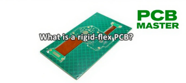
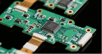
A Rigid-Flex PCB combines rigid sections (like traditional PCBs) with flexible polyimide ribbons. Think of it as an electronic “spine”: rigid parts provide stability for components, while flexible strips bend and twist to fit tight spaces. Designers can create complex 3D shapes and achieve optimal spatial configurations by carefully configuring the rigid and flexible zones.
For example:
Rigid zones use FR-4 material (common in PCBs) to anchor chips and sensors.
Flexible zones use polyimide films thinner than paper (≤0.1mm) to enable folding. When folding or bending, the width of the bending line is a key design parameter, along with bend angle and radius.
Why It Outshines Traditional PCBs
Rigid PCBs are cheap and sturdy but inflexible—useless for curved devices.
Flexible PCBs bend freely but lack support for heavy components. Rigid-Flex solves both problems: It’s a unified board that bends and bears weight.
Materials and Construction: The Hidden Backbone
Peek beneath the surface of any cutting-edge rigid flex PCB, and you’ll find a carefully engineered blend of materials working in harmony. The secret to their versatility lies in the combination of rigid and flexible sections—each chosen for its unique strengths.
Rigid zones are typically built from tried-and-true FR4, a staple in rigid printed circuit boards, providing a solid foundation for mounting components and ensuring mechanical stability. But it’s the flexible sections—crafted from high-performance polyimide material—that give rigid flex circuits their signature ability to bend, twist, and fit into the most unconventional spaces. Polyimide stands out for its remarkable heat resistance, chemical durability, and the ability to endure countless cycles of flexing without fatigue, making it the go-to choice for flexible circuits in demanding environments.
But materials are just the beginning. The copper thickness in rigid flex PCBs is meticulously selected to match the electrical demands of each application. Whether it’s a lightweight wearable or a power-hungry automotive sensor, designers can specify copper layers from 0.5 oz to 2 oz, balancing current-carrying capacity with flexibility. These copper conductors are often plated with nickel and gold, ensuring every connection remains reliable and corrosion-free—even after years of use.
The magic continues in the manufacturing process. Advanced techniques like laser drilling and precision routing allow for ultra-fine features and tight tolerances, essential for today’s miniaturized electronics. Each layer—rigid or flexible—must be perfectly aligned and bonded, a feat that demands both skill and state-of-the-art equipment. The result? Rigid flex boards with enhanced reliability, ready to withstand harsh environments and rigorous testing.
Designing a rigid flex PCB is as much an art as it is a science. Engineers must carefully consider the interplay between rigid and flexible materials, the optimal copper thickness, and the unique requirements of each circuit. Specialized design software and simulation tools help predict how the board will behave under stress, ensuring that every bend and flex meets the highest standards of durability and performance.
In the end, it’s this thoughtful combination of materials, precision manufacturing, and smart design that gives rigid flex PCBs their edge—enabling the next generation of electronic products to be lighter, more reliable, and more adaptable than ever before.
4 Game-Changing Advantages
Space Savings & MiniaturizationDevices are shrinking, but features are expanding. Rigid-Flex PCBs fold into 3D shapes, boosting space efficiency by 40%+. This makes them suitable for complex geometries and space-constrained designs.
Example: Apple’s Vision Pro uses 12-layer Rigid-Flex boards for its eyeball-tracking sensors.
Smartwatches like Huawei Watch GT4 pack more sensors into tighter curves.
Superior ReliabilityBy eliminating connectors and cables (common failure points), Rigid-Flex cuts failure rates by 70% in high-vibration environments. Comprehensive test procedures are used to ensure performance and reliability before installation.
Tesla’s battery systems use them for IP67 waterproofing.
They endure 100,000+ bends (e.g., in foldable phones).
High-Speed PerformanceFor 5G and AI chips, signal integrity is critical. These boards reduce interference with:
Laser-drilled microvias (holes ≤0.1mm) for precise connections.
Loss rates as low as 0.35dB/inch at 10GHz.
Cost Efficiency Long-TermWhile upfront costs are higher (5–11× traditional PCBs), they slash assembly time and repair needs. Rigid-Flex PCBs reduce assembly costs by minimizing the need for connectors and simplifying the assembly process, which lowers overall expenses. For EVs and medical gear, this means 20% lower lifetime costs.
Fast lead time and advanced manufacture capabilities make rigid-flex PCBs suitable for time-sensitive and complex applications.
Where You’ll Find Rigid-Flex PCBs Today

Consumer Electronics
Foldable Phones: Samsung’s Galaxy Z Fold uses them in hinges for durability, where connector design is crucial for reliable folding and unfolding.
AR/Glasses: Meta Quest 4’s HDI boards link 12 cameras, with careful connector integration for compact assembly.
Healthcare Innovation
Swallowable Endoscopes: Biocompatible Rigid-Flex boards transmit HD video for 72 hours stomach acid. Rigid-flex PCBs are widely used in medical devices for their reliability and adaptability.
Pacemakers: Flexible sections adapt to human motion, making them ideal for critical medical devices.
Automotive & Aerospace
Self-Driving Cars: LiDAR sensors in Teslas rely on heat-resistant boards (enduring -55°C to 155°C). Different materials are selected for optimal heat dissipation and performance in extreme environments.
Satellites: Polyimide-copper alloys survive space’s extreme temperatures, with material choices supporting both heat dissipation and mechanical reliability.
Industrial RobotsRobotic arms use Rigid-Flex joints for seamless movement without cable wear.
Behind the Scenes: Design Challenges

Creating these boards isn’t easy. Key hurdles include:
Material Matching: Rigid and flexible layers must expand/contract equally with heat. The design process and careful material selection are guided by detailed specifications to ensure manufacturability and reliability in rigid flex designs.
Bend Radius: Too tight a fold cracks circuits. Designers use simulations to avoid fatigue. In advanced rigid flex designs, flex design and maintaining signal integrity are critical challenges that must be addressed.
Costly Prototyping: Free samples are rare—a small board costs ~$22 (vs. $2 for rigid PCBs). Understanding manufacturing processes and planning the assembly process are essential for manufacturability, especially in complex rigid flex designs.
Pro Tip: Some manufacturers offer “pseudo-Rigid-Flex” kits for cheap testing.
Laser-drilled microvias are often used, where precise hole creation is essential for high-density interconnects.
The Future: AI, Green Tech, and Beyond
Smarter Manufacturing
AI vision systems now detect defects with 99.9% accuracy.
Eco-Friendly Materials
New Frontiers
Brain-Computer Interfaces (e.g., Neuralink) use ultra-thin boards for neural.
6G Ready: LCP materials enable terahertz-speed data10.
Why This Matters to You
Rigid-Flex PCBs aren’t just for engineers. They’re the reason your devices are:
More powerful (e.g., AI phones with faster data).
More durable (e.g., survival in rain or dust).
Sleeker (e.g., invisible tech woven into clothes).
As demand grows—11.2% yearly through 2028—prices will fall, making them the new norm.
Conclusion: The Invisible Revolution
From smartwatches to Mars rovers, Rigid-Flex PCBs are the unsung heroes enabling innovation. They represent a perfect marriage of strength and adaptability—a lesson in engineering elegance.
As we march toward a smarter, more connected world, this technology will quietly power the breakthroughs we can’t yet imagine.
Want to Learn More?Check out manufacturers like (Jabil) or (SCC) for cutting-edge case studies. For a deeper dive into rigid-flex PCB design and applications, consult our detailed blog post for comprehensive information.
FAQs
Q.What is a Rigid-Flex PCB?
A.
A Rigid-Flex PCB, or rigid-flex printed circuit board, combines the stability of rigid PCBs with the flexibility of flexible PCBs. It is typically composed of rigid sections (such as commonly used FR-4 material, which provides support and secures electronic components) and flexible sections (such as polyimide material, which enables bending and folding) connected through specialized processes. This structure allows for efficient electrical connections and adaptable layouts within complex spaces.
Q. Why is the manufacturing cost of Rigid-Flex PCBs relatively high?
A.
·Material Costs: Flexible materials like polyimide are more expensive than traditional rigid PCB materials. Additionally, meeting specific performance requirements may necessitate the use of special materials, further increasing costs.
·Equipment and Process Costs: Manufacturing requires high-precision equipment, such as advanced laminating machines, etching machines, and drilling machines. The procurement and maintenance of this equipment are costly. The manufacturing process is complex, involving precise alignment and lamination of rigid and flexible boards, specialized etching and cover film application for flexible sections, and multiple laminations and drillings for multilayer boards. This demands extremely stringent process control and experienced operators, raising labor costs.
·Yield Impact: Production is prone to defects such as delamination, short circuits, and open circuits, resulting in relatively lower yields and indirectly increasing production costs.
Q. What are the design challenges of Rigid-Flex PCBs?
A.
·Material Compatibility Issues: The thermal expansion coefficients of rigid and flexible materials must be matched; otherwise, exposure to heat can lead to delamination, cracking, and other issues that affect the board’s performance and lifespan.
·Complex Bend Radius Design: Precisely planning the bending areas and bend radii of flexible sections is critical. Excessively tight bends can cause circuit breaks, and repeated bending may lead to degraded electrical performance. Simulation tools are often required to avoid fatigue-related problems.
·High Comprehensive Design Requirements: Design must account for multiple aspects, including material selection, structural layout, electrical connectivity, and thermal management for both rigid and flexible sections. Considerations such as signal integrity and rational component placement make the design complexity far greater than that of traditional PCBs.
Q. What are the advantages of Rigid-Flex PCBs?
A.
·Space Savings: Capable of three-dimensional bending and folding, they enable flexible layouts in tight or irregular spaces, improving space utilization and facilitating product miniaturization. For example, they allow efficient use of internal space in products like smartwatches and foldable smartphones.
·High Reliability: By reducing the use of connectors and cables—common points of failure—they lower the probability of issues such as loose connections and poor contact. They perform exceptionally well in high-vibration and high-impact environments, such as in automotive electronics and aerospace equipment, where stable operation is critical.
·Improved Signal Integrity: More direct and continuous internal electrical connections help control signal transmission paths and impedance matching, reducing signal reflection, attenuation, and interference. This makes them suitable for high-speed signal transmission applications, such as 5G communication and high-performance computing.
·Excellent Long-Term Cost Efficiency: Although initial manufacturing costs are higher than those of traditional PCBs, unit costs decrease with mass production. Additionally, reduced assembly steps and lower maintenance needs result in cost savings over the product’s entire lifecycle.
Why choose PCBMASTER: https://www.pcbmaster.com/why
Join us: https://www.pcbmaster.com/login
