


The Ultimate Guide to FPC Copper Thickness-How to choose the copper thickness
Introduction
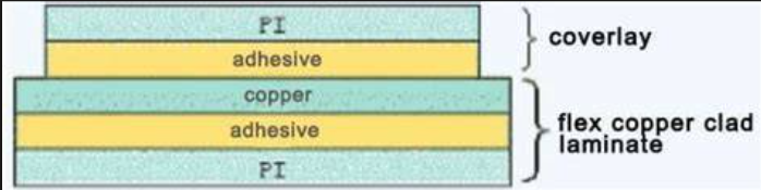
In the design and manufacturing of Flexible Printed Circuit Boards (FPCs), there is a parameter that seems simple but acts like the thickness of blood vessels in the human body, critically influencing the entire system's "health" and performance—that is copper thickness. Choosing the wrong copper thickness can lead to circuit overheating, signal distortion, or even total device failure. This article will take you deep into the intricacies of FPC copper thickness, providing a comprehensive selection guide from fundamental concepts to practical application.
FPC Copper Thickness Basics: More Than Just Numbers
The "Language" of Copper Thickness: Ounces vs. Microns
FPC copper thickness is typically expressed in "ounces per square foot" (oz/ft²), a unit with historical roots. A 1-ounce copper thickness means one ounce (approx. 28.35 grams) of copper covers one square foot of substrate. Converting to a more intuitive unit of thickness:
1 oz ≈ 35 micrometers (μm)
0.5 oz ≈ 17.5 micrometers
2 oz ≈ 70 micrometers
For perspective, a human hair is about 70-100 micrometers in diameter. So, a 2-ounce copper layer is roughly the thickness of a single strand of hair. While seemingly minuscule, this thin layer of copper foil is the "expressway" for electrical current, and its thickness directly dictates the circuit's current-carrying capacity.
Key Differences Between FPC and Rigid PCB Copper Thickness
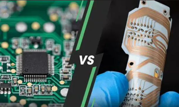
Unlike rigid PCBs, FPC copper foil is generally thinner because of:
·Flexibility Requirements: Thicker copper reduces bendability.
·Weight and Space Constraints: FPCs are often used in slim, lightweight devices.
·Manufacturing Process Differences: FPCs employ more precise etching techniques.
How Copper Thickness Affects Five Key FPC Performance Areas
Electrical Performance: The "Hard Metric" of Current Carrying Capacity
Current carrying capacity is the most direct factor influenced by copper thickness. Simply put, thicker copper can handle higher current. Here's a rule-of-thumb formula:
Current Carrying Capacity ≈ Copper Thickness × Trace Width × A Constant Coefficient
For 1-ounce copper, general guidelines are:
·For a 10°C temperature rise: ~1-1.5 Amps per millimeter of trace width.
·For a 20°C temperature rise: ~1.5-2 Amps per millimeter of trace width.
For example, a 0.5mm wide, 1oz thick FPC trace can carry approximately 0.75-1A with a 20°C temperature rise. To carry 2A, you would need to either increase the width to 1-1.3mm or raise the copper thickness to 2 ounces.
Signal Integrity: The "Invisible Guardian" of High-Speed Signals
In high-frequency applications, the skin effect becomes significant. High-frequency current tends to flow near the conductor's surface, reducing the effective conductive thickness.
·Above 10MHz: The skin effect becomes noticeable.
·Above 100MHz: Surface roughness impact outweighs that of total copper thickness.
·Above 1GHz: Special surface treatments are often required.
An Interesting Fact: For some high-frequency applications, thinner copper foil with good surface treatment can outperform thicker foil because it reduces edge effects and reflections.
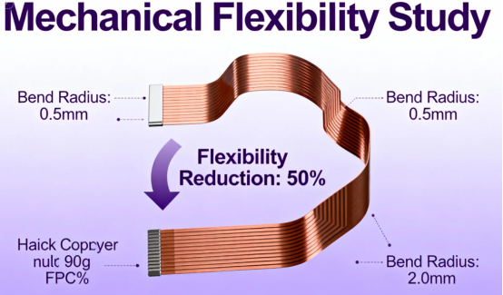
Mechanical Performance: The "Balancing Act" of Flex Life
The core advantage of FPCs is flexibility, and copper thickness directly impacts this property:
·Thin Copper (0.5-1 oz): Ideal for dynamic flexing applications (e.g., hinges, sliding parts).
·Thick Copper (2 oz and above): Better suited for static or minimal-flex applications.
Design Tip: For areas requiring frequent bending, consider a graduated copper thickness design—thicker near connectors, thinner in the bend zones.
Thermal Management: The "Regulator" of Heat Dissipation
Copper is an excellent conductor of both electricity and heat. Thicker copper layers:
·Distribute heat more evenly.
·Reduce local hot spot temperatures.
·Enhance overall reliability.
In applications like LED strips or automotive electronics, appropriate copper thickness selection is a crucial part of thermal management.
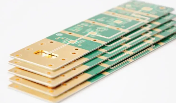
Manufacturing & Cost: The "Double-Edged Sword" of Economics
Copper thickness directly impacts manufacturing costs:
·Material Cost: Copper foil constitutes 15-30% of an FPC's raw material cost.
·Etching Difficulty: Thicker copper requires longer etch times and makes fine-line fabrication more challenging.
·Yield Impact: Thick copper is more prone to undercut issues during etching.
Application Scenarios & Practical Copper Thickness Selection Guide
Consumer Electronics: Balancing Slimness and Performance
| Application Scenario | Recommended Copper Thickness | Key Considerations |
|---|---|---|
| Smartphone Hinge Area | 0.5-1 oz | Dynamic flex life > 100,000 cycles |
| Wearable Devices | 0.5-1 oz | Slim, lightweight, flexible |
| Tablet Connections | 1 oz | Signal integrity & adequate current carry |
| Camera Modules | 0.5-1 oz | Fine lines, high density |
Case Study: A leading brand's foldable phone uses 0.5oz copper in the hinge area FPC to ensure reliable operation after 200,000 fold tests, while locally using 2oz copper in the power delivery sections to handle higher current.
Automotive Electronics: Testing Reliability and Endurance
Automotive applications demand extremely high reliability:
·Engine Compartment: 2-3 oz, for high-temperature and vibration resistance.
·In-Vehicle Displays: 1-2 oz, balancing signal quality and flexibility.
·Battery Management Systems: 2-4 oz, for high-current carrying capacity.
Medical & Special Applications: Meeting Extreme Requirements
·Medical Implants: 0.5-1 oz, with biocompatible coatings over thin copper.
·Military/Aerospace: 1-3 oz, for tolerance to extreme temperature cycling.
·Industrial Controls: 1-2 oz, for noise immunity and long-term reliability.
Practical Design Tips for FPC Copper Thickness
1.Hybrid Copper Thickness Design: The Optimal Solution
Modern FPC manufacturing allows for different copper thicknesses on the same board:
·Local Thickening: Use thicker copper for power paths and ground planes.
·Local Thinning: Use thinner copper in high-density interconnect areas.
·Gradual Transitions: Avoid stress concentration caused by abrupt thickness changes.
Practical Formulas for Copper Thickness Calculation
For scenarios requiring precise calculation:
Required Copper Thickness (oz) = (Current (A) × Resistivity Constant) / (Allowed Temp Rise (°C) × Trace Width (mm) × Heat Dissipation Factor)
Simplified rule: Plan for approximately 0.5-1 sq. mm of copper cross-sectional area per 1 Amp of current (depending on the allowed temperature rise).
Avoiding Common Design Pitfalls
Myth 1: Thicker copper is always better.
Reality: Excessive thickness reduces flexibility, increases cost, and complicates etching.
Myth 2: Use the same copper thickness for all traces.
Advice: Design differentially based on current requirements.
Myth 3: Ignoring high-frequency effects.
Reminder: Above 100MHz, consider skin depth, not just total thickness.
Future Trends: New Developments in FPC Copper Thickness Technology
·Ultra-Thin Copper: 5-9 micrometer (≈0.25 oz) foils for ultra-high-density interconnects.
·Profile-Modified Foils: Copper foil with locally variable thickness for optimized performance and cost.
·Composite Copper Layers: Layers combining copper with other metals to balance conductivity and mechanical properties.
·Stretchable Copper Mesh: Special structures for use in stretchable electronics.
Conclusion: Finding Your "Goldilocks Thickness"
There is no one-size-fits-all answer for selecting FPC copper thickness. It is a delicate balance between electrical needs, mechanical demands, thermal management, and cost control. When choosing, ask yourself these four key questions:
·What is my maximum current requirement?
·What kind of bending or dynamic stress will the circuit undergo?
·What is the operating frequency range?
·What is the budget?
Remember: The optimal copper thickness is the thinnest option that meets all your requirements—this controls cost while enhancing flexibility and manufacturing yield.
In the fast-evolving world of electronics, understanding the subtleties of FPC copper thickness is key to designing reliable, high-performance flexible circuits. Whether you're developing the next generation of wearables or advanced automotive systems, the right copper thickness choice will be a vital component of your success.
FAQs
Q: What are the common copper thickness specifications for FPCs?
A: Common specifications include 9μm, 12μm (0.33oz), 18μm (0.5oz), and 35μm (1oz). Thicker copper options like 2oz and 3oz are also available for high-current applications.
Q: How does copper thickness affect the flexibility of an FPC?
A: Thinner copper offers greater flexibility, enabling tight-radius bending or repeated folding. Thicker copper is less flexible and is better suited for applications with minimal bending or fixed installations.
Q: What are the trace width/space requirements for different copper thicknesses?
A: The typical (and minimum achievable) requirements are:
·For 12μm (0.33oz) copper: 3/3 mil (minimum 2/2 mil).
·For 18μm (0.5oz) copper: 3.5/3.5 mil (minimum 3/3 mil).
·For 35μm (1oz) copper: 4/4 mil (minimum 3.5/3.5 mil).
Q: What copper thickness is suitable for FPCs in folding screen smartphones?
A: Thin copper, such as 9μm or 12μm, is typically chosen. This balances the need for high-flexibility to withstand frequent folding with the requirements for fine-pitch wiring.
Q: Which copper thickness should be selected for high-current scenarios (e.g., BMS in new energy vehicles)?
A: Thick copper of 35μm (1oz) or above (2oz/3oz) is recommended. It provides lower electrical resistance to handle high currents and offers greater mechanical strength.
Q: How does copper thickness impact FPC manufacturing/processing?
A: Thin copper is easier to process into fine traces, making it suitable for high-density layouts. Thick copper is more difficult to etch accurately, which can lead to trace width deviations and limits the ability to achieve fine features.
Author: Jack Wang

