


What Is ATE in PCBA Testing? A Complete Guide to Automated Test Equipment
In modern electronics manufacturing, every printed circuit board assembly (PCBA) must meet strict standards for reliability and performance. As circuits become more compact and complex, manual inspection is no longer enough to ensure flawless functionality. This is where Automated Test Equipment (ATE) steps in—bringing precision, speed, and consistency to the heart of the testing process. By simulating real-world operating conditions and automatically verifying circuit behavior, ATE helps manufacturers detect faults early, optimize yield, and maintain the quality demanded by today’s high-performance devices.
Introduction to ATE and PCBA Testing
What Is ATE (Automated Test Equipment)?
Automated Test Equipment (ATE) refers to a system that automatically evaluates the functionality and performance of electronic components or printed circuit board assemblies (PCBAs). Instead of relying on manual probing or visual inspection, ATE applies electrical signals, measures the responses, and determines whether a device meets design specifications.
An ATE system typically includes four main components:
1. Hardware interfaces — physical connections that link the test equipment to the device under test (DUT).
2. Test software — programs that define test sequences, parameters, and pass/fail criteria.
3. Measurement instruments — modules that generate signals, collect data, and analyze results.
4. Data systems — tools that store, visualize, and report test outcomes for traceability and optimization.
A simple example can be found in smartphone PCB assembly lines, where functional testers automatically verify whether each circuit performs correctly—checking power output, signal integrity, and communication between chips. This automation not only accelerates testing but also minimizes human error, ensuring consistent quality across large production volumes.
The Role of Testing in PCBA Manufacturing
Testing is a critical stage in PCBA manufacturing because it ensures that every assembled circuit board operates as intended before integration into a final product. The main purposes of PCBA testing are to detect defects early, verify circuit reliability, and prevent costly rework or product failures after shipment.
There are several common testing methods used throughout the manufacturing process:
ICT (In-Circuit Test) — checks electrical connections and component placement.
FCT (Functional Circuit Test) — validates that the entire board functions under normal operating conditions.
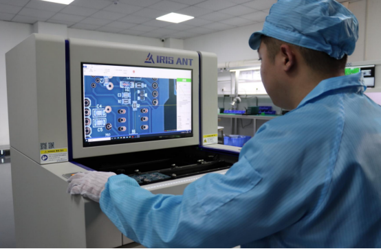
AOI (Automated Optical Inspection) — uses cameras to visually detect soldering and component errors.
ATE (Automated Test Equipment) — provides comprehensive, programmable electrical testing with precise measurement capabilities.
Compared to manual testing, automated systems like ATE deliver much higher speed, accuracy, and scalability. While manual inspection depends on human judgment and can vary from operator to operator, ATE applies consistent procedures and objective measurements, making it ideal for high-volume and high-reliability production environments.
In short, ATE represents the evolution of PCBA testing—from reactive quality control to proactive, data-driven assurance that every circuit board performs flawlessly.
How ATE Works in PCBA Testing
The Basic Working Principle of ATE
Automated Test Equipment (ATE) operates by automatically applying a series of predefined electrical tests to a Printed Circuit Board Assembly (PCBA) to verify its functionality and performance. The system executes these tests through automated sequences controlled by software, collecting measurement data in real time.
ATE simulates real-world conditions through input-output emulation. It sends electrical signals (voltage, current, or digital patterns) to the Device Under Test (DUT) and measures the responses to check whether they meet the expected specifications. For example, in a PCBA used in automotive electronics, ATE might simulate temperature sensors or communication buses to ensure each circuit behaves correctly under load.
A typical ATE workflow begins with test program initialization, where the system loads the proper test parameters for the specific board type. During the test run, the ATE executes automated measurement sequences, compares results against preset thresholds, and finally classifies each board as PASS or FAIL. The complete process is software-driven, ensuring consistency, speed, and accuracy across large production batches.
Main Components of an ATE System
An ATE system is composed of several key components that work together to perform automated testing:
Test Head / Measurement Unit – The central hardware that generates test signals and measures electrical responses. It includes instruments such as signal generators, digital multimeters, and power supplies.
Fixture / Interface Board – The mechanical and electrical interface connecting the ATE to the Device Under Test (DUT). It ensures stable contact and reliable signal transmission during testing.
Test Software – The control layer that defines test logic, manages parameters, and sequences the measurements. It automates decisions and communicates with the operator or production line system.
Data Analysis System – Collects, stores, and visualizes test data. It provides yield statistics, failure trends, and traceability for process optimization and quality control.
Together, these components create a closed-loop testing environment capable of detecting functional, electrical, or performance issues before final assembly or shipment.
Typical ATE Test Flow in PCBA Production
A typical ATE test flow in PCBA manufacturing follows a structured sequence to ensure efficiency and repeatability:
Step 1: Board Preparation and Fixture Connection
The PCBA is cleaned, visually inspected, and mounted into the test fixture. Proper alignment ensures accurate contact between the test pins and the DUT pads.
Step 2: Test Program Execution
The operator starts the automated test sequence. The ATE loads the correct test profile for that PCB model and begins applying test signals according to the program’s logic.
Step 3: Measurement and Data Acquisition
During testing, the system measures voltages, currents, timing responses, or communication signals. All results are automatically recorded and compared to tolerance limits defined in the test plan.
Step 4: Result Classification and Report Generation
After execution, the ATE system classifies each board as PASS, FAIL, or RETEST. A detailed report is generated, which may include failure points, performance graphs, and statistical summaries for quality tracking.
This standardized test flow helps PCBA manufacturers maintain high reliability, reduce manual inspection time, and provide data-driven quality assurance.
Types of ATE Used in PCBA Testing
Functional Test Systems (FCT)
Functional Test Systems (FCT) are designed to verify whether a fully assembled PCB operates correctly under real-world conditions. Instead of testing individual components, FCT evaluates the entire circuit’s functional performance, ensuring that signals, voltages, and communication paths behave as expected.
During an FCT, the board is powered on and exposed to simulated input signals. The tester then monitors the output responses to confirm that the PCBA performs according to its design. This type of testing is essential for identifying system-level issues such as timing errors, faulty interfaces, or component mismatches that might not be caught by earlier inspections.
A common example is testing power supply boards or communication modules, where FCT verifies voltage stability, output accuracy, and data transfer reliability. Because it closely mirrors the board’s real working environment, FCT provides a final layer of assurance before the product enters mass production or shipment.
In-Circuit Test (ICT) ATE
In-Circuit Test (ICT) is one of the most widely used forms of ATE in high-volume PCBA production. It focuses on testing each component individually while the board is not powered, allowing engineers to detect open circuits, short circuits, incorrect components, or soldering defects.
ICT systems use a bed-of-nails fixture or probe array that makes contact with test points across the PCB. When a test program runs, the ATE measures electrical parameters such as resistance, capacitance, and voltage drop to confirm that every part is correctly installed and functioning.
Because ICT can quickly identify assembly errors before final testing, it plays a vital role in early fault detection and process control. Manufacturers often combine ICT with FCT to achieve full test coverage—ICT for structural integrity, and FCT for functional validation.
Boundary Scan / JTAG-Based ATE
Boundary Scan ATE, often referred to as JTAG-based testing, is used for complex circuit boards with high-density integrated circuits (ICs), such as those in telecommunications and computing equipment. This method allows test access through a digital interface embedded within the chips themselves, eliminating the need for physical probes.
The JTAG standard (IEEE 1149.1) enables direct communication with components over a serial connection, allowing the tester to check internal logic states, signal paths, and interconnections. This makes it particularly valuable for fine-pitch or multilayer PCBs where physical probing is difficult or impossible.
By integrating boundary scan capabilities into ATE, manufacturers can reduce fixture costs, speed up diagnostics, and perform advanced debugging during both production and field maintenance.
Flying Probe ATE
Flying Probe ATE is a highly flexible test system that uses moving probes instead of fixed fixtures to make contact with the board. Because it does not require a custom fixture, it’s ideal for prototype testing, low-volume runs, and rapid design validation.
During testing, multiple probes move across the PCB to measure voltages, resistance, and connectivity. The system can adapt test points and angles dynamically, making it efficient for handling design changes or new product introductions.
Comparison – Flying Probe vs. ICT vs. Functional ATE:
Feature | Flying Probe ATE | ICT ATE | Functional ATE (FCT) |
|---|---|---|---|
Fixture Requirement | None | Required | Required or semi-custom |
Best Use Case | Prototyping & small batches | Mass production | Final product validation |
Speed | Moderate | Very fast | Variable (depends on test complexity) |
Coverage | Electrical and connection tests | Structural and component-level | Functional and performance-level |
Flexibility | High | Low | Medium |
Flying probe systems offer maximum flexibility and low setup cost, but they are generally slower than ICT and FCT, making them better suited for engineering verification rather than large-scale production.
In practice, manufacturers often combine these ATE types across different production stages—ICT or flying probe for early fault detection, JTAG for high-density diagnostics, and FCT for final functional verification—ensuring complete, reliable PCBA testing coverage.
Benefits of Using ATE in PCBA Testing
Efficiency and Speed
One of the biggest advantages of Automated Test Equipment (ATE) in PCBA testing is its ability to perform tests faster and more efficiently than manual methods. By automating signal application, data measurement, and analysis, ATE drastically reduces the test cycle time per unit and minimizes the need for human intervention.
In a typical production environment, automated testing can increase throughput by 30–50%, depending on board complexity and test setup. For example, instead of spending several minutes manually checking each circuit, an ATE system can complete the same process in seconds while simultaneously logging results for traceability.
This efficiency allows manufacturers to maintain high production speeds without compromising quality—an essential advantage for industries like telecommunications, automotive electronics, and consumer devices, where time-to-market is critical.
Accuracy and Repeatability
ATE delivers precise and repeatable testing results by eliminating human variability and ensuring that every board is tested under the same controlled conditions. Automated systems use calibrated instruments and pre-programmed test sequences, guaranteeing that each measurement is consistent across thousands of units.
This consistency significantly reduces false positives and false negatives, two common problems in manual testing. For instance, a faulty solder joint or marginal component that might be overlooked by a human operator can be reliably detected by ATE’s high-resolution sensors and digital analysis tools.
The result is greater confidence in product reliability, especially for mission-critical electronics such as aerospace control units or medical devices, where accuracy cannot be compromised.
Scalability for Mass Production
ATE systems are highly scalable and can be easily integrated into large-scale automated production lines. Once configured, they can handle continuous operation with minimal supervision, making them ideal for high-volume PCBA manufacturing.
Many modern ATE platforms connect directly to Manufacturing Execution Systems (MES) or factory automation networks, allowing test data to be instantly uploaded, analyzed, and shared across the production floor. This integration supports real-time quality monitoring and rapid feedback loops for process optimization.
For manufacturers scaling production or managing multiple product lines, ATE ensures consistent performance while maintaining flexible test configurations for different PCB designs.
Cost Optimization Over Time
Although the initial investment in ATE can be significant, it delivers strong long-term cost savings through automation, accuracy, and process efficiency. By detecting defects early and reducing manual labor, ATE lowers the cost of rework, scrap, and field failures—all of which can be far more expensive than preventive testing.
Over time, the return on investment (ROI) becomes clear: faster test cycles lead to higher throughput, fewer production stoppages, and improved yield. In high-volume environments, even a few seconds saved per unit can translate into substantial annual savings.
In short, ATE is not just a testing tool—it’s a strategic investment that supports continuous improvement, scalability, and cost efficiency across the entire PCBA manufacturing process.
Challenges and Limitations of ATE
High Setup and Calibration Cost
One of the main challenges of implementing Automated Test Equipment (ATE) is the high initial setup and calibration cost. Most ATE systems require custom fixtures tailored to specific PCB designs, along with dedicated programming to define test sequences, parameters, and pass/fail criteria.
For manufacturers with low-volume production, these upfront costs can make ATE less cost-effective, as the ROI may take longer to achieve. In contrast, high-volume production lines benefit significantly from ATE because the per-unit savings in labor, time, and rework quickly offset the initial investment. Understanding this ROI threshold is critical for deciding whether ATE is a strategic fit for a particular production environment.
Limited Flexibility for Design Changes
Another limitation of ATE, especially fixture-based systems, is their reduced flexibility when PCB designs change. If a layout is revised—such as moving components, changing board size, or adding new test points—the existing fixture may no longer align with the board’s contact points, requiring costly redesign or adjustment.
For example, a minor change in a smartphone PCB layout could render an ICT fixture incompatible, delaying testing and production schedules. While some modern ATE platforms offer programmable or flying-probe options to mitigate this, the issue remains a consideration for boards that undergo frequent design iterations.
Skilled Personnel Requirement
Operating and maintaining ATE systems requires highly trained engineers. These personnel are responsible for designing test programs, calibrating instruments, troubleshooting errors, and interpreting test data accurately.
Without skilled staff, even the most advanced ATE may produce unreliable results or experience downtime, reducing its efficiency and ROI. Manufacturers must invest not only in equipment but also in training and retaining qualified personnel to ensure consistent, accurate, and timely PCBA testing.
In summary, while ATE offers significant advantages in efficiency and accuracy, it comes with challenges that include high upfront costs, limited flexibility for design changes, and the need for skilled operators. Manufacturers must weigh these factors carefully to ensure that the benefits of automated testing outweigh the limitations in their specific production context.
How to Select the Right ATE for Your PCBA Project
Key Selection Criteria
Choosing the right Automated Test Equipment (ATE) starts with evaluating the specific requirements of your PCBA project. The most important factors include:
Product Complexity: Highly dense or multilayer PCBs with advanced ICs may require boundary-scan or flying-probe capabilities, while simpler boards can rely on ICT or functional testers.
Production Volume: High-volume production benefits from fast, fixture-based ICT or FCT systems, whereas low-volume or prototype testing favors flexible flying-probe solutions.
Test Coverage Requirements: Consider whether you need structural testing, functional verification, or both. Full test coverage ensures that both individual components and overall board performance meet specifications.
Budget and Infrastructure: Factor in the initial equipment cost, space requirements, power, cooling, and maintenance capabilities. Aligning ATE selection with your infrastructure helps maximize ROI.
By assessing these criteria, manufacturers can match their testing strategy with the right ATE type, avoiding overspending on unnecessary capabilities or under-testing critical features.
Comparing Vendor Solutions
When evaluating vendors, it’s essential to consider speed, accuracy, support, and software compatibility. These factors directly affect testing efficiency, reliability, and ease of integration with existing processes.
For example, comparing Teradyne and Keysight systems illustrates key differences:
Teradyne: Known for high-throughput ICT solutions and extensive fixture support, suitable for large-scale production lines.
Keysight: Offers flexible functional and precision measurement systems with advanced software analytics, ideal for high-performance or complex boards.
Additional considerations include warranty, local technical support, training availability, and software updates. A detailed vendor comparison matrix can help teams make a data-driven choice aligned with their project needs.
Integration with Production Systems
Modern ATE systems should seamlessly integrate with production management platforms like ERP (Enterprise Resource Planning) or MES (Manufacturing Execution Systems). Integration enables real-time test data collection, traceability, and analytics, supporting quality control and continuous improvement initiatives.
Interoperability with existing test equipment is equally important. For example, if a factory already uses ICT and flying-probe systems, adding a new ATE should allow data sharing and centralized reporting without extensive custom programming.
By prioritizing integration and interoperability, manufacturers ensure that ATE contributes to a connected, efficient, and data-driven production environment, enhancing both testing reliability and operational visibility.
This approach allows manufacturers to select ATE systems that meet technical requirements, scale efficiently, and integrate smoothly into their overall production ecosystem, maximizing both performance and long-term value.
Future Trends in ATE and PCBA Testing
AI and Machine Learning in Test Optimization
Artificial intelligence (AI) and machine learning (ML) are transforming ATE systems by enabling predictive failure analysis and adaptive test programs. AI algorithms can analyze historical test data to identify patterns and predict which components or boards are most likely to fail.
For example, an ML-based ATE system can adjust test sequences dynamically—focusing more on high-risk areas while reducing redundant checks—thereby reducing overall test time without sacrificing coverage. This approach improves yield prediction and supports proactive maintenance, enhancing both production efficiency and product reliability.
Cloud-Based Test Data Management
Cloud integration is emerging as a key trend for centralized test data storage and real-time analytics. By uploading ATE test results to a cloud platform, manufacturers can monitor quality metrics across multiple factories and production lines, enabling global visibility and faster decision-making.
For instance, a company with PCB assembly plants in different regions can compare failure rates in real time, identify systemic issues, and adjust production parameters remotely. Cloud-based management also simplifies reporting, traceability, and compliance, ensuring that test data is accessible for both engineers and quality managers at any time.
Miniaturization and High-Speed Digital Testing
As devices shrink and circuit densities increase, ATE systems must adapt to miniaturized PCBs and high-speed digital circuits. The rise of 5G, IoT, and advanced wearable devices demands testing solutions capable of handling extremely fine-pitch components and high-frequency signal integrity verification.
Modern ATE platforms now include precision measurement instruments, high-speed digital channels, and low-noise probing techniques to ensure accurate testing of compact, high-performance boards. These capabilities are critical to maintaining signal fidelity, reliability, and compliance with industry standards in next-generation electronics.
Green Testing and Energy Efficiency
Sustainability is becoming a priority in electronics manufacturing. Low-power ATE systems and energy-efficient test strategies help reduce electricity consumption and minimize the environmental impact of large-scale testing operations.
Examples include dynamic power scaling, where the tester adjusts energy usage based on board complexity, and batch testing optimizations that reduce idle time. Implementing these green practices supports corporate sustainability goals while maintaining cost-effective and reliable PCBA testing.
By embracing these trends—AI-driven optimization, cloud-based data management, miniaturized high-speed testing, and sustainable practices—manufacturers can future-proof their PCBA testing processes, ensuring efficiency, accuracy, and environmental responsibility in an increasingly competitive electronics industry.
Conclusion
Automated Test Equipment (ATE) plays a crucial role in ensuring the reliability and performance of PCBA products. By providing precise, consistent, and efficient testing, ATE helps manufacturers detect defects early, verify functional integrity, and maintain high-quality standards across every board. Whether through functional testing, in-circuit testing, or advanced boundary-scan methods, ATE ensures that PCBA assemblies meet design specifications and operate reliably in real-world applications.
For manufacturers aiming to remain competitive in the fast-paced electronics industry, strategic adoption of ATE is essential. The ability to combine speed, accuracy, and scalability allows production lines to increase throughput while reducing costs associated with rework or field failures.
At PCBMASTER, a professional PCB and PCBA supplier, every board undergoes rigorous, high-quality testing before delivery. Leveraging advanced ATE systems, PCBMASTER ensures that each PCBA meets strict reliability standards, reflecting the company’s commitment to high-performance, high-quality electronic products.
In summary, integrating ATE into PCBA production is not just a technical upgrade—it is a strategic investment in quality assurance, operational efficiency, and long-term manufacturing success.
FAQs
1. What’s the difference between ATE and ICT in PCBA testing?
Automated Test Equipment (ATE) is a broad term for systems that automatically test electronic components or assembled PCBs, often including functional testing, in-circuit testing, and boundary-scan testing.
In-Circuit Test (ICT) is a specific type of ATE focused on checking individual components and connections on a PCB. ICT uses a fixture (bed-of-nails) to detect open circuits, shorts, and incorrect components before the board is powered on.
Key difference: ATE can include ICT but also covers broader functional and system-level testing, whereas ICT is specialized for structural and component-level verification.
2. How much does it cost to implement ATE for PCB manufacturing?
The cost of ATE varies widely based on board complexity, production volume, and test type:
Low-volume or prototype testing (flying-probe systems) can start at $50,000–$100,000.
High-volume production with ICT or functional testers may exceed $250,000–$500,000 due to custom fixtures, software programming, and calibration requirements.
While the initial investment is high, the long-term ROI comes from reduced labor, lower rework costs, faster test cycles, and improved yield.
3. Can ATE be used for both prototype and mass production testing?
Yes. ATE is flexible enough for both use cases, but the type of system may differ:
Prototypes or low-volume boards often use flying-probe testers that require no custom fixtures and can adapt quickly to design changes.
Mass production typically uses ICT or functional testers with dedicated fixtures for faster throughput and consistent results.
This flexibility allows manufacturers to maintain consistent quality across all production stages.
4. What software tools are typically used to program ATE systems?
ATE systems are controlled by specialized test software that defines test sequences, parameters, and reporting:
Vendors often provide proprietary tools, e.g., Teradyne’s TestStand or Keysight PathWave Test.
Some systems support scripting or programming languages like Python, C++, or proprietary test languages for custom test routines.
Advanced software includes data analytics modules to visualize results, track trends, and optimize test programs.
The choice of software affects ease of programming, integration, and data management.
5. How is ATE evolving with Industry 4.0 and smart factory trends?
ATE is increasingly integrated with Industry 4.0 technologies to enhance automation, data management, and decision-making:
AI and machine learning analyze test data to predict failures and optimize test sequences.
Cloud-based platforms enable centralized monitoring, real-time analytics, and traceability across multiple production sites.
Connected ATE systems interface with MES/ERP systems to improve workflow efficiency, quality control, and resource planning.
Miniaturization and high-speed testing support next-generation 5G, IoT, and wearable electronics.
These trends make ATE not just a testing tool, but a key component of smart, data-driven manufacturing.

