Ultra-Thin Rigid-Flex PCBs for AR Glasses: Key Applications, Challenges, and Solutions
Augmented reality (AR) glasses are transforming the way we interact with the digital world, pushing the boundaries of what’s possible in wearable technology. To achieve the ultra-lightweight, high-performance, and space-efficient designs required for AR applications, manufacturers are turning to ultra-thin, subminiature rigid-flex PCBs. These advanced components play a pivotal role in integrating complex electronics, from sensors and display modules to power systems, all within the incredibly compact and flexible framework needed for AR glasses. As the demand for smarter, lighter, and more durable AR devices grows, these cutting-edge PCBs are becoming the backbone of next-gen eyewear technology, offering solutions to some of the industry's most challenging design obstacles.
What Are Ultra-Thin and Subminiature Rigid-Flex PCBs?
Definition of Rigid-Flex PCBs
Rigid-flex PCBs are a type of printed circuit board that combines both rigid and flexible sections into one unified structure. This hybrid design allows parts of the PCB to be stiff and provide strong mechanical support, while other sections remain flexible to bend or fold. The rigid areas typically hold heavier components like chips, power management systems, and sensors, while the flexible areas allow the PCB to fit into tight or curved spaces, making it ideal for complex, space-constrained devices such as AR glasses. These PCBs are often made with materials like FR-4 (for the rigid part) and PI (Polyimide) or LCP (Liquid Crystal Polymer) (for the flexible part).
The typical thickness for ultra-thin rigid-flex PCBs ranges from 0.15mm to 0.35mm, making them incredibly lightweight and compact. This makes them perfect for use in devices where space is limited, such as AR glasses, where every millimeter counts.
Why the Ultra-Thin Design Is Crucial for AR Glasses
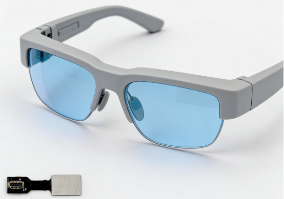
Ultra-thin rigid-flex PCBs are essential for AR glasses because they help meet the stringent demands of lightweight design and compact form factor. AR glasses typically need to weigh no more than 35g to ensure they are comfortable for everyday wear. The rigid-flex PCB plays a key role in keeping the overall weight down without compromising the functionality of the device.
In addition to reducing weight, these PCBs enable the tight, compact spaces required by AR glasses. The lens frames of these glasses can be as narrow as 8mm, and the PCB must fit into these tight spaces while still supporting complex components like sensors, cameras, and displays. Without ultra-thin, subminiature rigid-flex PCBs, creating AR glasses with such compact dimensions would be impossible.
For example, in some AR glasses, ultra-thin rigid-flex PCBs are used in the side frames and lens systems to provide the necessary strength and flexibility, while maintaining the slim profile needed for sleek, wearable technology.
What Are the Key Applications of Ultra-Thin Rigid-Flex PCBs in AR Glasses?
Ultra-thin rigid-flex PCBs play a crucial role in enabling the advanced functionality and sleek design of AR glasses. These versatile components are integrated into key areas such as the lens frame, optical module, sensor systems, and battery supply, offering both flexibility and strength. By combining rigid and flexible areas in one compact design, they help minimize weight, maximize space efficiency, and ensure reliable performance in the most demanding AR applications.
Lens Frame / Side Frame (Most Critical Area)
In AR glasses, the lens frame or side frame is a critical component that houses various electronic systems. Ultra-thin rigid-flex PCBs play a key role in integrating both rigid and flexible areas to support different components within tight spaces.
l Rigid Area: The rigid section of the PCB is used to support essential components such as the System on Chip (SoC), power management, memory, radio-frequency (RF) modules, and sensors like IMU (Inertial Measurement Unit), ToF (Time of Flight), and microphones. These components require solid support to maintain stability, which is why the rigid PCB areas are designed to be stiff and durable.
l Flexible Area: The flexible section of the PCB connects the rigid components, allowing the PCB to bend and conform to the shape of the glasses. This section enables the lens frame and optical module to stay connected while accommodating movements like bending and opening/closing. The flexibility helps reduce the weight of the glasses by 40%, making them more comfortable for extended wear.
Real-World Examples:
Popular AR glasses utilize ultra-thin rigid-flex PCBs in their side frames. These glasses often feature 4 to 8 layers of ultra-thin rigid-flex boards, ensuring that components can be securely placed without adding excessive bulk.
Optical Module and Display System
Ultra-thin rigid-flex PCBs are used to integrate various high-performance components in the optical module and display system, which are essential for delivering the AR experience.
l Integration of Optical Components: These PCBs are responsible for supporting optical waveguides, MicroLED, and LCoS (Liquid Crystal on Silicon) technologies within ultra-small spaces. For example, the optical module may fit in a 10×10×5mm area, where the rigid-flex PCB helps route signal connections, power, and driving functions.
l Signal & Power Distribution: The rigid-flex PCB acts as the backbone for transmitting signals, providing power to components, and handling sensor integration. This is vital to ensure that high-quality visuals are displayed on the lenses, with high refresh rates like 4K/120Hz for smooth viewing.
Challenges:
The use of ultra-thin rigid-flex PCBs in optical modules comes with significant challenges:
l Micron-Level Alignment: Precise alignment of the components is required to ensure that everything fits perfectly within the limited space.
l Heat Dissipation: As AR systems demand high-performance displays and sensors, heat management becomes crucial to prevent damage to sensitive components.
l Optical Interference: The PCB must minimize any interference with light paths to maintain clear, high-quality images in AR displays.
Sensor & Nose Bridge Integration
Ultra-thin rigid-flex PCBs are key to integrating sensors and other miniaturized electronics within the nose bridge of AR glasses, which is often a compact area.
l Sensor Integration: The nose bridge houses multiple sensors, including cameras for vision tracking, environmental sensors (such as light or temperature sensors), and bone conduction technology for audio. Ultra-thin rigid-flex PCBs provide the necessary flexibility and stability to fit these components into a small space while ensuring all components work efficiently.
l Space Efficiency: Rigid-flex PCBs help reduce the size of these components, ensuring that they fit comfortably without adding unnecessary bulk to the glasses. This is especially important since the nose bridge is one of the smallest and most critical areas for AR glasses.
Example:
In some devices, the nose bridge contains sensors and audio systems integrated using ultra-thin rigid-flex PCBs, allowing the glasses to remain lightweight while performing complex tasks.
Battery & Power Supply System
The battery and power supply system in AR glasses must be efficient and compact, and ultra-thin rigid-flex PCBs provide a crucial solution by enabling flexible interconnections between the battery, mainboard, and optical module.
l Flexible Interconnections: These PCBs allow for ultra-thin flexible connections that link the battery to the rest of the system, even through the bending areas of the glasses. This flexibility is vital for the glasses to fold or bend without breaking or losing functionality.
l Durability: Ultra-thin rigid-flex PCBs are designed to withstand 100,000+ bend cycles, ensuring that the interconnections remain intact even after extended use. This durability solves traditional issues with wire breakage and space-consuming wires, improving the overall reliability of the device.
Example:
In AR glasses, ultra-thin rigid-flex PCBs enable the flexible connection of the battery to the mainboard and display, helping to reduce weight and ensure long-lasting power while maintaining durability and flexibility.
Why Are Ultra-Thin and Subminiature Rigid-Flex PCBs Necessary for AR Glasses?
Ultra-thin and subminiature rigid-flex PCBs are essential for AR glasses due to their unique ability to combine both rigidity and flexibility in a compact design. These PCBs are critical for achieving the slim, lightweight, and durable form factor required for AR glasses, ensuring they fit into tight spaces while supporting high-performance components.
Comparison: Rigid PCBs, FPC, and Ultra-Thin Rigid-Flex PCBs
Ultra-thin rigid-flex PCBs strike the perfect balance between the structural support of rigid PCBs and the flexibility of FPCs, making them the ideal choice for AR glasses. Let's compare these three types of PCBs to understand why ultra-thin rigid-flex PCBs are essential for the compact, high-performance designs of AR glasses.
| PCB Type | Rigid PCBs | Flexible PCBs (FPC) | Ultra-Thin Rigid-Flex PCBs |
| Thickness | ≥0.4mm | 0.05–0.15mm | 0.15–0.35mm |
| Flexibility | Not flexible (rigid) | Highly flexible | Balanced flexibility (rigid and flexible sections) |
| Structural Support | Strong structural support for heavy components | Lacks support, prone to deformation | Combines support for heavy components with flexibility |
| Suitability for Bending | Not suitable for bending or tight spaces | Can bend, but may deform under pressure | Ideal for bending, folding, and tight spaces |
| Space Efficiency | Low space efficiency due to thickness | Good space efficiency, but limited by lack of structure | High space efficiency, fits compact AR designs |
| Applications | Large devices (e.g., desktop electronics) | Small flexible applications (e.g., wearables) | AR glasses, wearable tech, compact and high-performance devices |
Rigid PCBs (≥0.4mm thick)
Rigid PCBs are typically used in larger electronic devices where space is less constrained. However, they are not suitable for applications requiring bending or compact 3D spaces, like AR glasses. Their thickness (usually ≥0.4mm) makes them too bulky for the slim, lightweight designs that AR glasses demand. In addition, rigid PCBs lack flexibility, making them unsuitable for dynamic applications like folding or bending.
Example: Traditional consumer electronics such as TVs and desktop computers often use rigid PCBs for their stability but wouldn’t be practical for wearable tech like AR glasses.
Flexible PCBs (0.05–0.15mm thick)
FPCs are thinner than rigid PCBs, typically ranging from 0.05mm to 0.15mm, and they are great for applications requiring flexibility. However, FPCs often lack the structural support needed for heavy components like SoCs (System on Chips) or memory modules. Without the support of rigid areas, FPCs can deform under pressure, which can lead to failure in the demanding environments of AR glasses.
Example: Smartphones and wearable fitness trackers use flexible PCBs in their flexible circuits, but these devices generally don’t require as much component support as AR glasses do.
Ultra-Thin Rigid-Flex PCBs (0.15–0.35mm thick)
Ultra-thin rigid-flex PCBs combine the best features of rigid and flexible PCBs. They range from 0.15mm to 0.35mm thick, making them both lightweight and highly flexible. These PCBs are ideal for AR glasses, where space is tight and flexibility is essential. The rigid sections provide the support needed for critical components, while the flexible sections allow for bending, folding, or adapting to tight spaces like lens frames.
Why Ultra-Thin Rigid-Flex PCBs Are Perfect for AR:
l Optimal Space Usage: They allow for efficient use of space in small areas, which is crucial for AR glasses that need to be compact and lightweight.
l High Reliability: These PCBs are reliable for repeated bending, ensuring that they can withstand the daily use of AR glasses, which often involve folding and bending.
l Perfect for AR Applications: The combination of rigidity and flexibility ensures that AR glasses can be durable and perform optimally in demanding environments.
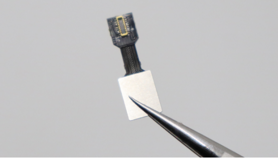
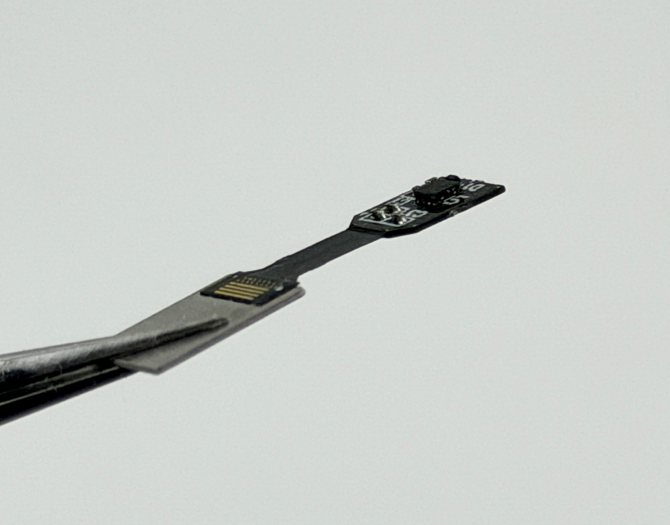
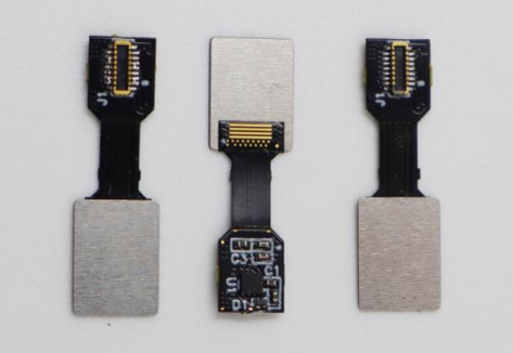
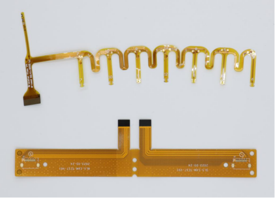
Example: PCBMASTER's ultra-thin and subminiature rigid-flex PCB, at just 0.35mm thick, features a 4-layer structure made from PI SF202 and SY S1000-2M materials, ensuring both flexibility and durability. With a minimum track/spacing of 2/2 mil and a 0.10mm drill size, it guarantees high precision and reliability even in tight spaces. The ENIG surface finish ensures excellent signal integrity and corrosion resistance. These combined features make it ideal for AR glasses, offering a lightweight, high-performance, and flexible solution for integrating complex components in compact designs.
What Are the Core Challenges of Ultra-Thin Rigid-Flex PCBs in AR Glasses?
Ultra-thin rigid-flex PCBs are essential for AR glasses, but their integration comes with several challenges. From managing material stress and precision manufacturing to handling high-frequency signals and ensuring durability, each aspect requires careful attention.
Material and Thermal Stress
Ultra-thin rigid-flex PCBs face significant material and thermal stress challenges, especially due to the difference in thermal expansion rates between rigid and flexible materials.
l Coefficient of Thermal Expansion (CTE) Mismatch: Rigid PCBs are typically made from materials like FR-4, while flexible areas use PI (Polyimide) or LCP (Liquid Crystal Polymer). These materials expand and contract at different rates when exposed to temperature changes. This CTE mismatch can cause delamination or warping over time as the materials expand at different rates.
l Thermal Cycling Issues: Frequent exposure to heat and cold (such as when AR glasses are worn in different environments) can lead to circuit breakage or damage from thermal cycling. This process can weaken the PCB and make it prone to failure over time.
The solution often involves selecting materials with compatible thermal expansion properties or designing PCBs that can manage these stresses through advanced engineering.
Precision Manufacturing Limitations
Ultra-thin rigid-flex PCBs require extreme precision during manufacturing, which becomes more difficult as designs become smaller and more complex.
l Fine Trace Widths and Spaces: The lines and spaces on ultra-thin PCBs can be as small as ≤50um (around 1/20th the thickness of a human hair). This precision is required to handle high-frequency signals in small, tight spaces. Even a slight error in trace width or spacing can cause short circuits or performance issues.
l Hole Sizes: To fit into compact spaces, ultra-thin rigid-flex PCBs often have holes as small as ≤0.1mm, which are difficult to create. This requires laser drilling or high-precision etching techniques, which must be flawless to avoid issues like burrs or cracked holes.
l Layer Alignment: With 4-8 layers in a typical rigid-flex PCB, ensuring accurate layer alignment is critical. Misalignment can result in short circuits, weak connections, or even complete PCB failure. The acceptable tolerance for alignment is typically ±15um.
All of these manufacturing challenges make producing ultra-thin rigid-flex PCBs costly and time-consuming, requiring high-end equipment and strict quality control.
Rigid-Flex Transition Zone
The transition zone between the rigid and flexible sections of ultra-thin rigid-flex PCBs is a critical area where stresses often accumulate.
l Stress Concentration: During bending or folding, the rigid-flex transition zone becomes a weak point where stress can concentrate. This can lead to cracks, trace breakage, or even delamination of the layers.
l Window Design and Reinforcement: To prevent failures in the transition zone, special window designs and reinforcement techniques are used. These can include designing rounded corners, using reinforcing materials, or adding reinforcement layers to absorb the stress and prevent damage.
These design and material considerations are vital for ensuring the long-term durability of the PCB in AR glasses, especially given that the glasses will often be bent or folded during use.
High-Frequency and EMI Challenges
Ultra-thin rigid-flex PCBs must handle high-frequency signals while avoiding issues like signal attenuation, crosstalk, and impedance mismatch, all of which can affect AR performance.
l Signal Attenuation and Crosstalk: As the PCB becomes thinner and more compact, signal degradation and crosstalk between signal traces become more pronounced. This is especially problematic for high-speed signals required in AR systems (such as MIPI, LVDS, or PCIe). These issues can result in degraded image quality or slower processing speeds.
l Impedance Mismatch: Maintaining proper impedance (especially for high-frequency signals) in thin, fine-line designs is crucial for signal integrity. Even small deviations in trace width or spacing can lead to significant impedance mismatch, affecting the performance of the AR glasses.
l EMI/EMC Control: Managing electromagnetic interference (EMI) and ensuring electromagnetic compatibility (EMC) is challenging in compact designs with multiple high-speed signals. Poor EMI control can lead to interference with optical components, sensors, or other electronics, impacting the overall functionality of the glasses.
Effective design techniques, such as careful shielding, layer stacking, and controlled impedance routing, are essential to mitigate these challenges.
Reliability and Mass Production Challenges
The reliability of ultra-thin rigid-flex PCBs over time and their mass production are two significant challenges that must be addressed to ensure the long-term performance of AR glasses.
l Bend Cycle Durability: One of the most critical challenges is ensuring that the PCB can withstand 100,000+ bend cycles without failure. AR glasses are often folded or bent during use, so the PCB must be flexible enough to endure frequent movement without breaking or losing electrical connectivity.
l Low Yield in Mass Production: Ultra-thin, multi-layer designs are difficult to produce in large quantities without defects. The combination of thin materials, precise manufacturing, and complex layer stacking leads to low production yields and high manufacturing costs. Many manufacturers struggle to achieve yields greater than 60-70%, making mass production challenging and expensive.
The solution to these challenges lies in advanced manufacturing techniques, such as automated assembly, improved materials, and better quality control, to ensure higher yields and more reliable production at scale.
What Are the Key Solutions to Overcome These Challenges?
To overcome the challenges of ultra-thin rigid-flex PCBs in AR glasses, a combination of strategic material selection, advanced manufacturing techniques, innovative design improvements, and thorough reliability testing is essential.
Material Selection for Thermal and Structural Optimization
The right materials can help minimize issues like thermal expansion mismatch and improve both flexibility and durability.
l LCP (Liquid Crystal Polymer): LCP is an ideal material for the flexible regions of ultra-thin rigid-flex PCBs because of its low Coefficient of Thermal Expansion (CTE). This helps reduce thermal stress between rigid and flexible areas, which can prevent issues like delamination and warping. LCP also offers excellent high-frequency performance, which is essential for AR applications.
l High-Tg FR-4: For the rigid sections, high-Tg FR-4 is used. This material has a higher glass transition temperature (Tg), allowing it to match better with flexible regions in terms of thermal properties. It provides the required rigidity while helping maintain thermal stability and structural integrity.
l RA Copper (Rolled Annealed Copper): RA copper is more resistant to bending fatigue than traditional copper. It improves the PCB's ability to withstand repeated bending and flexing (required for AR glasses), which is essential for ensuring long-term reliability.
By using these materials, manufacturers can address key issues like CTE mismatch, thermal stress, and flexibility, which are crucial for ensuring the durability and functionality of ultra-thin rigid-flex PCBs.
Advanced Manufacturing Techniques
The precision required for ultra-thin rigid-flex PCBs demands specialized manufacturing processes to achieve the necessary quality and performance.
l Lamination: Stepwise temperature control, segmented pressure application, and vacuum lamination help ensure a uniform thickness across the PCB layers. These processes prevent warping and delamination during lamination, ensuring consistent performance throughout the PCB’s lifespan.
l Drilling: Laser drilling with blue and red light is used to create precise holes as small as 0.1mm. This level of precision is critical for ensuring high-quality connections in small, densely packed PCBs, reducing errors like burrs or fractures.
l Plating and Etching: Pulse reverse current helps to create a uniform plating thickness, ensuring better signal integrity and reliability. Fine-line etching techniques, such as the SAP method, allow for the creation of narrower traces and fine-line features, which are essential for high-speed signal transmission in AR glasses.
l Positioning and Alignment: Full-area optical alignment and shrinkage compensation techniques are used to ensure precise layer-to-layer alignment in multi-layer PCBs. These techniques are crucial for maintaining signal integrity and preventing misalignment that can lead to short circuits or loss of connectivity.
These manufacturing techniques are necessary to produce ultra-thin rigid-flex PCBs that meet the high standards required for AR applications, ensuring both precision and reliability.
Design Improvements for Stress Relief and Flexibility
Smart design practices can reduce mechanical stress in ultra-thin rigid-flex PCBs, increasing their longevity and functionality.
l Teardrop Pads and Large Radius Corners: Using teardrop-shaped pads and large radius corners in the design reduces stress concentrations, particularly at connection points. This helps avoid potential cracks or trace breakage caused by bending or flexing.
l Gradual Thickness Changes: Instead of sharp transitions between different thicknesses, gradual thickness changes help evenly distribute mechanical stress across the PCB. This design approach minimizes areas of high stress, which is especially critical in flexible zones.
l Low-Stress Windows: Low-stress windows are strategically placed in areas that are prone to bending. These windows help reduce the likelihood of material failure by allowing for more flexibility and less strain on the PCB.
l Reinforcements: Reinforcing critical areas with ultra-thin PI (Polyimide) and stainless steel can help balance flexibility with strength. These reinforcements add mechanical stability while maintaining the PCB's ability to bend without fatigue failure.
Through these design improvements, manufacturers can ensure that ultra-thin rigid-flex PCBs have both the necessary flexibility and durability required for the demanding environments of AR glasses.
Reliability Testing and Validation
Reliability testing ensures that ultra-thin rigid-flex PCBs meet performance standards over time, especially in the challenging environments in which AR glasses are used.
l Bending Tests: To ensure long-term durability, ultra-thin rigid-flex PCBs undergo bending tests to simulate real-world conditions. These tests require the PCB to endure ≥100,000 cycles of bending without failure, ensuring they can withstand the daily flexing and folding of AR glasses.
l Thermal Cycling: Thermal cycling tests (-40°C ~ 125°C) are conducted to ensure that the PCB can endure extreme temperature changes without delaminating, warping, or losing performance. These tests simulate how the PCB will react to real-world temperature fluctuations that AR glasses experience.
l High-Frequency Testing: Since AR glasses rely heavily on high-speed signals, high-frequency tests (such as 5GHz) are used to ensure insertion loss and impedance stability. These tests validate the PCB’s ability to maintain signal integrity without degrading the quality of the signal, which is critical for AR applications.
By performing these rigorous tests, manufacturers can ensure that their ultra-thin rigid-flex PCBs can handle the mechanical, thermal, and high-frequency demands of AR glasses, ensuring long-lasting performance and reliability.
What Are the Typical Parameters for AR Glasses PCBs?
When designing PCBs for AR glasses, several key parameters determine their performance and suitability. Let’s explore the typical specifications, such as thickness, trace width, hole size, and more, that ensure these PCBs meet the demanding requirements of AR applications.
Total Thickness: 0.18–0.35mm (4–8 layers)
The total thickness of AR glasses PCBs typically ranges from 0.18mm to 0.35mm, depending on the number of layers. These ultra-thin designs are crucial to meet the strict size and weight requirements of AR glasses, ensuring they remain lightweight and comfortable for long-term wear. Generally, 4 to 8 layers are used, with each layer performing specific functions like signal processing, power management, and data transmission. Thinner boards are preferred to maximize space inside the device, allowing for compact designs and integration of multiple components.
Trace Width/Spacing: 25/25um–50/50um
Trace width and spacing refer to the size of the conductive pathways and the gaps between them. For AR glasses PCBs, the typical range for trace width/spacing is between 25/25um and 50/50um. These fine traces enable the PCB to handle the high-frequency signals required for the smooth operation of AR systems. The narrower the trace, the more circuits can fit within the limited space, allowing for more functionality and better integration of components. Maintaining the precise width and spacing ensures optimal performance and signal integrity, especially for high-speed signals that are critical for AR functionality.
Minimum Hole Size: 0.1mm (laser blind hole)
The minimum hole size for AR glasses PCBs is typically 0.1mm, which is achieved using laser drilling techniques for blind holes. This ultra-precise drilling method allows for the creation of smaller vias (holes) that connect different layers of the PCB without compromising the integrity or performance of the board. Smaller hole sizes are essential to fit within the tiny space constraints of AR glasses, enabling efficient use of space and maintaining reliable electrical connections between layers, especially in high-density circuit designs.
Bend Lifetime: ≥100,000 cycles
Since AR glasses are worn on the face and require constant bending and folding, the bend lifetime of the PCB is critical. The typical bend lifetime for AR glasses PCBs is ≥100,000 cycles, ensuring that the PCB can withstand frequent folding and flexing without failure. This is especially important for the flexible sections of the PCB, which are subjected to constant physical stress when the glasses are put on and taken off, or adjusted. Ensuring a long bend lifetime is crucial for the overall durability and longevity of the AR glasses.
Impedance Control: ±5% (50Ω/90Ω/100Ω)
Impedance control ensures that the electrical signals transmitted through the PCB maintain a stable and predictable flow, which is critical for high-speed communication in AR glasses. The typical impedance control for AR glasses PCBs is ±5%, with standard values of 50Ω, 90Ω, or 100Ω, depending on the application. Proper impedance control minimizes signal reflections and losses, ensuring that high-speed signals, such as those required for display modules and sensors, remain clear and accurate. This control is essential for maintaining signal integrity and reliable performance in AR systems.
Application: Lens Frames, Optical Modules, and Sensor Modules
AR glasses PCBs play a vital role in several key areas of the device:
l Lens Frames: The PCB connects various components, including sensors and processing units, within the lens frames, which need to be ultra-thin and compact.
l Optical Modules: The optical modules of AR glasses are responsible for displaying augmented reality content. The PCB facilitates the integration of light guides or MicroLEDs and ensures the efficient transmission of signals to display systems.
l Sensor Modules: These modules include motion sensors, cameras, and environmental sensors. The PCB provides necessary connections and power distribution to ensure seamless operation and data collection for AR functions like gesture recognition and spatial awareness.
In all these applications, the PCB must be designed to be compact, durable, and capable of handling the high-speed signals needed for AR functionality.
What Does the Future Hold for Ultra-Thin Rigid-Flex PCBs in AR Glasses?
The future of ultra-thin rigid-flex PCBs in AR glasses is filled with exciting advancements. From further miniaturization to innovative materials and improved manufacturing, these developments promise to enhance performance, reduce weight, and create more powerful and efficient AR devices.
Trends in Miniaturization and Thinness
The future of ultra-thin rigid-flex PCBs for AR glasses will see even greater miniaturization and thinner designs. Manufacturers aim to reduce the thickness of PCBs to below 0.35mm, allowing for even more compact AR glasses. As technology advances, trace widths as small as 20um and hole sizes as tiny as 0.05mm will become achievable. These advancements will help fit more functionality into the limited space available in AR glasses, enabling the integration of additional sensors, higher-performance optical systems, and smaller, more efficient power management circuits—all while maintaining the glasses' sleek and lightweight profile.
Material Innovations
In the future, new materials will play a critical role in improving the performance and reliability of ultra-thin rigid-flex PCBs. Materials like low-CTE (Coefficient of Thermal Expansion) PI (polyimide) will be used more widely to ensure better thermal compatibility between rigid and flexible areas, minimizing issues such as warping and delamination. Ultra-thin LCP (liquid crystal polymer) will provide even better performance, particularly in high-frequency applications, while nano-copper will further enhance conductivity and bend resistance. These materials will help AR glasses achieve higher durability and better performance in challenging environments.
Increasing Integration
The integration of both passive and active components within a single, compact PCB will be a major trend. Future designs will see further miniaturization, where not just the PCB but also components like resistors, capacitors, and semiconductors will be integrated into 3D stacked configurations. This will allow for even more efficient use of space, reducing the overall size and weight of AR glasses. As a result, AR glasses will become even thinner, lighter, and more comfortable for everyday use while maintaining high performance and functionality. This integration will also help to reduce costs by minimizing the number of components and simplifying the assembly process.
Manufacturing Improvements
As demand for ultra-thin rigid-flex PCBs grows, manufacturing technologies will continue to improve. Process technologies will mature, allowing for automated production with higher consistency and fewer defects. Yield rates, currently less than 60%, will improve significantly to 85% or higher, which will lower the overall cost of production. More automated lines will reduce human error and improve scalability, making the production of AR glasses more cost-effective and accessible. These improvements will enable higher-volume production of ultra-thin rigid-flex PCBs, which is essential for meeting the growing demand for AR glasses in the consumer market.
Conclusion
Ultra-thin rigid-flex PCBs are at the heart of the next generation of AR glasses, offering the perfect balance of lightweight design, flexibility, and high-performance signal transmission. These PCBs are crucial for meeting the strict size, weight, and durability requirements of AR applications, enabling smaller, sleeker devices that do not compromise on functionality.
As materials and manufacturing processes continue to evolve, ultra-thin rigid-flex PCBs will only get better. New innovations in materials like low-CTE polyimides and ultra-thin LCP, combined with advancements in precision manufacturing, will allow for even more compact, reliable, and high-performing AR devices. Additionally, the increasing integration of passive and active components into these PCBs will further push the boundaries of what is possible, offering AR glasses with better performance and enhanced user experiences.
In conclusion, ultra-thin rigid-flex PCBs are essential for the future of AR glasses, and as technology continues to evolve, they will play a key role in creating lighter, more powerful, and more reliable AR devices.
FAQs
What is the main difference between rigid-flex PCBs and traditional PCBs?
Rigid-flex PCBs combine both rigid and flexible sections in a single board. The rigid sections provide support for components like microchips and connectors, while the flexible sections allow the PCB to bend and conform to specific shapes. This hybrid structure is ideal for devices like AR glasses, where components need to be placed in compact spaces, but the PCB must also withstand frequent bending. In contrast, traditional PCBs are fully rigid and cannot bend, making them less suitable for applications requiring flexibility, like AR glasses, where space optimization and durability are critical.
How do ultra-thin rigid-flex PCBs benefit AR glasses specifically?
Ultra-thin rigid-flex PCBs are lightweight, flexible, and high-performance, making them perfect for AR glasses. The thinness (usually around 0.35mm or less) allows for a slim profile, which is essential for maintaining a sleek design in AR devices. Additionally, these PCBs can withstand bending while maintaining functionality, crucial for AR glasses that require flexibility in the frame for comfort and performance. They also support high-frequency signal transmission, making them ideal for the complex components in AR glasses, such as microLEDs, sensors, and optical systems. These characteristics enable AR glasses to be compact, efficient, and reliable.
What challenges do manufacturers face when creating ultra-thin rigid-flex PCBs for AR glasses?
Creating ultra-thin rigid-flex PCBs for AR glasses presents several challenges:
l Material Mismatches: The different materials used for the rigid and flexible areas, such as FR-4 (rigid) and PI or LCP (flexible), often have different Coefficient of Thermal Expansion (CTE) values. This mismatch can lead to issues such as warping, delamination, or circuit breakage under thermal stress.
l Precision Manufacturing: Ultra-thin rigid-flex PCBs require extreme precision, especially in processes like drilling holes as small as 0.1mm or creating fine traces as narrow as 20um. The manufacturing must be accurate to avoid defects like circuit shorts or open circuits.
l Signal Integrity: High-frequency signals used in AR glasses can suffer from signal attenuation, crosstalk, and impedance mismatches if the PCB design isn’t optimized.
l Long-Term Durability: With AR glasses needing to withstand over 100,000 bend cycles, ensuring the durability of the ultra-thin PCB without compromising performance is a major challenge.
How long do ultra-thin rigid-flex PCBs last in AR glasses?
Ultra-thin rigid-flex PCBs in AR glasses are designed to endure over 100,000 bending cycles without failure. This ensures reliable long-term performance even with frequent bending in areas such as the temples or frame. These PCBs are specifically engineered for durability in flexible zones, making them ideal for AR glasses that require continuous folding, unfolding, or daily wear and tear. This longevity helps maintain the integrity of connections, prevents circuit failure, and ensures that AR glasses remain functional over time, despite the repetitive stresses they may face.
What future developments can we expect for ultra-thin rigid-flex PCBs in AR glasses?
The future of ultra-thin rigid-flex PCBs for AR glasses looks promising with several exciting developments on the horizon:
l Miniaturization: Expect to see even thinner designs, with trace widths shrinking to as small as 20um, and hole sizes dropping below 0.05mm. This will allow for further compaction of components, leading to even lighter and slimmer AR glasses.
l Material Innovations: New materials like nano-copper will help improve conductivity, bend resistance, and overall durability. Low-CTE PI (polyimide) and ultra-thin LCP will provide better thermal performance, reducing risks related to material mismatches and improving reliability.
l Increased Integration: Future developments will likely include 3D stacking of components and the integration of both passive and active elements on the same PCB. This will save space and weight, improving the overall design and performance of AR glasses.
l Manufacturing Improvements: As automated production continues to advance, manufacturers will see improved yield rates (from <60% to ≥85%) and reduced manufacturing costs. This will make ultra-thin rigid-flex PCBs more affordable and scalable, enabling mass production of high-quality AR glasses at lower prices.
These innovations will push the capabilities of AR glasses even further, enabling more powerful, compact, and efficient devices.
Author Bio
Hi, I'm Carol, the Overseas Marketing Manager at PCBMASTER, where I focus on expanding international markets and researching PCB and PCBA solutions. Since 2020, I've been deeply involved in helping our company collaborate with global clients, addressing their technical and production needs in the PCB and PCBA sectors. Over these years, I've gained extensive experience and developed a deeper understanding of industry trends, challenges, and technological innovations.
Outside of work, I'm passionate about writing and enjoy sharing industry insights, market developments, and practical tips through my blog. I hope my posts can help you better understand the PCB and PCBA industries and maybe even offer some valuable takeaways. Of course, if you have any thoughts or questions, feel free to leave a comment below—I'd love to hear from you and discuss further!