


Impedance Control in PCB Design: A Comprehensive Guide for High-Speed Signal Integrity
The demand for faster, more efficient electronic devices has made signal integrity a critical factor in PCB design. Impedance control is key to ensuring high-speed signals maintain their quality as they travel through the circuit. Without proper impedance management, issues like signal reflection, data loss, and interference can arise, compromising performance. In today’s electronics, mastering impedance control isn’t just a technical necessity—it’s the foundation for reliable and efficient designs. Understanding how to implement and manage impedance effectively is crucial for creating high-performance PCBs.
What is Impedance Control in PCB Design?
Impedance control in PCB design refers to the process of maintaining consistent electrical impedance across the circuit’s signal paths. Proper impedance control is crucial for high-speed and high-frequency circuit designs, as it ensures signal integrity by minimizing issues like reflection and data loss. The goal is to match the impedance of the signal path to the impedance of the source and receiver, allowing for reliable signal transmission.
Defining Impedance and Its Role in PCB Circuits
What is Impedance?
Impedance is the opposition that a circuit offers to the flow of alternating current (AC) signals, which combines the effects of resistance (R), capacitance (C), and inductance (L). It’s measured in ohms (Ω) and plays a critical role in how signals behave as they travel through a PCB. In high-speed circuit designs, impedance needs to be controlled to ensure signals travel without distortion or loss.
l Resistance (R): Resists the flow of current and causes energy dissipation.
l Capacitance (C): Stores and releases electrical energy, affecting signal propagation speed.
l Inductance (L): Resists changes in current and can cause delays in the signal.
Why is Impedance Matching Critical for High-Speed, High-Frequency PCB Designs?
Impedance matching is vital for high-speed, high-frequency PCBs because mismatched impedance can cause signal reflection, where the signal bounces back toward the source instead of continuing down the trace. This reflection can lead to errors in data transmission, signal loss, and timing problems. For high-frequency circuits like RF (radio frequency) or high-speed digital systems, controlling impedance ensures that the signal reaches its destination without interference or degradation.
Example: Imagine a highway with traffic moving at a steady speed. If there’s a sudden bump (impedance mismatch), the cars will slow down or stop, causing congestion and delays. Similarly, impedance mismatches disrupt smooth signal flow in PCB designs.
The Importance of Signal Integrity in High-Speed PCBs
How Does Improper Impedance Affect Signal Quality?
Signal integrity refers to the quality of an electrical signal as it travels through a circuit. When impedance is not properly controlled, several problems can arise, including:
l Signal Reflection: When the impedance at the signal path doesn’t match, part of the signal reflects back toward the source, causing errors or noise.
l Signal Loss: Mismatched impedance can also lead to excessive signal attenuation, weakening the signal over distance.
l Crosstalk: If impedance isn’t controlled between adjacent signal traces, electromagnetic interference (EMI) can cause one signal to interfere with another, leading to data corruption.
For example, in high-speed data communication, such as USB or HDMI, improper impedance control can result in dropped packets or degraded video/audio quality.
Example of High-Speed Signal Distortion Caused by Impedance Mismatches
A common example can be found in the design of Ethernet cables. If the impedance of the cable doesn’t match the network interface controller (NIC) at the receiving end, the result is data loss or packet errors. This issue becomes even more pronounced at higher speeds, where small imperfections in impedance matching can cause significant performance degradation. For instance, a mismatch might result in the Ethernet signal reflecting back into the cable, causing a network slowdown or complete failure of the connection.
In another case, consider the design of a high-frequency RF circuit used in mobile phones. Even a small impedance mismatch can cause interference that might lead to reduced signal strength, dropped calls, or slow data transfer speeds.
By understanding and controlling impedance, engineers can prevent these problems, ensuring that signals are transmitted clearly and reliably, even at high speeds.
Why is Impedance Control Crucial for High-Speed PCB Designs?
Impedance control is essential in high-speed PCB designs because it ensures the accurate transmission of electrical signals without distortion, interference, or loss. As modern electronics require faster speeds and higher frequencies, proper impedance control becomes critical to maintaining signal integrity and preventing costly performance issues.
The Impact of High-Speed Signals on PCB Performance
How Do High-Speed Signals Affect PCB Performance?
As circuits become faster, the signals they transmit must also travel at higher frequencies. High-speed signals are more sensitive to impedance mismatches because they have less time to settle, which means any distortion can lead to errors or delays. The performance of the PCB relies heavily on the integrity of these signals, so impedance control ensures they maintain their strength and clarity during transmission.
Real-World Applications of High-Speed Signals
High-speed signals are used in a variety of modern electronic devices and applications, including:
l RF (Radio Frequency) circuits: Used in communication systems such as mobile phones, Wi-Fi, and Bluetooth, where precise signal transmission is crucial for data exchange.
l USB: USB 3.0 and newer versions require precise impedance control for fast data transfer between devices like computers, phones, and peripherals.
l HDMI: High-Definition Multimedia Interface (HDMI) relies on impedance control to transmit high-definition video and audio between devices like televisions, gaming consoles, and computers without signal degradation.
l Ethernet: Network cables and devices (such as routers and switches) use impedance control to ensure reliable data transfer across local area networks (LANs) and the internet.
In all of these applications, signal integrity is paramount to prevent data loss, delays, or quality degradation. Proper impedance control in the PCB design ensures these devices function as intended, delivering high-speed, reliable performance.
Consequences of Poor Impedance Control
What Happens When Impedance Control is Not Managed Properly?
When impedance control is ignored or poorly managed, several serious issues can occur in the PCB design:
l Signal Reflection: A mismatch between the impedance of the signal line and the source/receiver causes part of the signal to reflect back. This reflection can interfere with the original signal, leading to data errors or communication failures.
l Timing Issues: Impedance mismatches can cause signals to arrive at different times, leading to synchronization issues. This can be particularly problematic in high-speed digital systems where precise timing is crucial.
l Data Corruption: With incorrect impedance, the integrity of the transmitted signal is compromised, causing the data to be corrupted, leading to transmission errors or even system crashes.
These issues can severely affect the performance of high-speed circuits, leading to system malfunctions, slow data transfer rates, or total failure in extreme cases.
How is Impedance Control Achieved in PCB Design?
Impedance control in PCB design involves carefully managing several factors that influence how electrical signals propagate through the circuit. By adjusting parameters such as trace width, spacing, material properties, and stack-up configuration, designers can ensure that impedance remains consistent and within desired specifications. Proper impedance control is essential for achieving signal integrity, especially in high-speed and high-frequency designs.
Key Parameters Influencing Impedance Control
What Are the Key Factors That Influence Impedance Control?
Several design parameters affect the impedance of signal traces on a PCB:
l Trace Width: The width of the signal trace directly impacts its impedance. Wider traces generally result in lower impedance, while narrower traces increase impedance. The ideal trace width depends on the required impedance value and the PCB’s material and structure.
l Trace-to-Ground Spacing: The distance between the signal trace and the ground plane also affects impedance. A smaller spacing between the trace and ground reduces the impedance, while larger spacing increases it. This relationship is particularly important for ensuring that signals are transmitted accurately without interference.
l PCB Stack-up: The arrangement of different layers within the PCB, including signal layers, ground planes, and power planes, determines the overall impedance of the signal path. A well-planned stack-up ensures that the signal trace’s impedance is consistent and matches the impedance of the source and receiver.
Material Properties: Dielectric Constant (Dk) and Loss Tangent (Df)
l Dielectric Constant (Dk): This property of the PCB material measures how much the material slows down the signal. A higher Dk value means that signals travel more slowly through the material, affecting the impedance. For example, materials like FR4 (commonly used for PCBs) have a Dk of around 4.5, while PTFE has a lower Dk value.
l Loss Tangent (Df): The loss tangent refers to the energy loss as signals pass through the material. Materials with lower loss tangent values (like PTFE) are preferred for high-frequency applications as they reduce signal attenuation and maintain integrity.
Example: Using a material with a high Dk value can lead to slower signal propagation, which may require designers to adjust trace width and spacing to compensate for the change in impedance.
Types of Impedance Control in PCB Design
Impedance control in PCB design can be achieved through different methods based on the type of signal being transmitted. The most common types of impedance control are single-ended impedance, differential impedance, and controlled impedance lines (microstrip and stripline).
Single-ended Impedance
What Is Single-ended Impedance and How is it Applied?
Single-ended impedance refers to the impedance between a signal line and a reference plane (usually ground). In this configuration, a single trace carries the signal, and the impedance is determined by the width of the trace, the distance to the reference plane, and the properties of the PCB material.
Common Values (50Ω, 75Ω) and Their Importance
l 50Ω: This is the most commonly used impedance value for high-speed digital signals, especially in applications like Ethernet and RF communication. It ensures that the signal integrity is maintained with minimal reflection and loss.
l 75Ω: Often used in applications where signal transmission over long distances is required, such as in video or analog signals (e.g., CCTV systems).
The correct impedance value is critical to avoid signal distortion, ensure high-speed data transfer, and prevent data loss.
Differential Impedance
What Is Differential Impedance and How Is It Used?
Differential impedance refers to the impedance between two signal traces carrying complementary signals (i.e., differential pairs). These pairs are used in high-speed applications where the signals are transmitted in opposite phases to reduce electromagnetic interference (EMI) and improve noise immunity.
Common Values for Differential Pairs (100Ω, 90Ω)
l 100Ω: This is the most common impedance value used for differential pairs, particularly in high-speed digital communication standards such as USB, HDMI, and PCIe.
l 90Ω: Sometimes used for specific applications where the layout or stack-up requires a slightly different impedance, such as in some RF and Ethernet designs.
Correctly matching the differential impedance ensures that signals are transmitted without distortion, especially in high-speed systems where data transfer rates are crucial.
Controlled Impedance Lines (Microstrip & Stripline)
What Are Microstrip and Stripline Structures?
l Microstrip: In a microstrip configuration, the signal trace is on the top layer of the PCB, with a ground plane underneath it. This configuration is most commonly used in surface-mount PCBs and is simple to design but can be affected by external noise.
l Stripline: In a stripline configuration, the signal trace is sandwiched between two ground planes within the PCB. This structure offers better shielding from external noise, making it ideal for high-frequency or high-precision applications.
How Do These Structures Affect Impedance?
Both microstrip and stripline structures provide controlled impedance for signal traces. The impedance of these lines is influenced by:
l The width of the signal trace.
l The distance between the trace and the reference planes (ground planes).
l The thickness of the PCB material.
Example: In high-frequency applications like RF circuits, stripline structures are often preferred for their superior shielding, which minimizes noise and maintains signal quality. On the other hand, microstrip is used in less demanding designs where cost and space are more critical considerations.
By carefully designing microstrip and stripline traces, designers can ensure that impedance is properly controlled for optimal signal integrity, minimizing issues like reflection and signal degradation.
What Are the Best Practices for Impedance Control in PCB Design?
Impedance control is critical to the successful design of high-speed PCBs, especially in today’s electronics where signal integrity is a key factor for performance. To ensure that signals are transmitted accurately and efficiently, several best practices should be followed during the design process. These practices help prevent signal reflection, loss, and interference, which can all cause data errors or even system failure.
Calculating and Choosing the Correct Trace Width
How Do You Calculate and Choose the Correct Trace Width?
Calculating the correct trace width is crucial for achieving the desired impedance in PCB design. The width of the trace directly impacts the impedance of the signal path. The key factors that influence this calculation include the trace’s material, the distance to the ground plane, and the target impedance value (e.g., 50Ω for single-ended or 100Ω for differential impedance).
Formula for Trace Width: The trace width can be calculated using the following formula, known as the IPC-2221 standard:
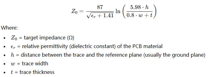
This formula allows you to determine the necessary trace width based on the PCB material and design parameters.
Software Tools and Calculators for Trace Width Selection
There are several tools and calculators available to help you determine the correct trace width based on these variables. Some popular options include:
l Online Trace Width Calculators: Websites like Advanced Circuits and Saturn PCB Design offer simple calculators where you input parameters like desired impedance, PCB material, and trace-to-ground spacing to get the trace width.
l PCB Design Software: Tools like Altium Designer, KiCad, and Autodesk Eagle have built-in impedance calculators that help automate trace width selection based on predefined rules and design constraints.
Using these tools ensures that the trace width is calculated accurately and efficiently, preventing issues in the final PCB design.
Managing Layer Stack-up for Proper Impedance Control
How Does Layer Stack-up Affect Impedance Control?
The layer stack-up of a PCB refers to how the different layers of the board are arranged, such as signal layers, ground planes, and power planes. The layer stack-up directly impacts the impedance of signal traces, especially when designing high-speed circuits.
2-Layer vs. 4-Layer Configurations:
l 2-layer PCB: In a two-layer design, the signal traces are typically on the top and bottom layers with no dedicated ground plane. This can cause higher impedance and more noise because the reference plane is not continuous, and signal quality may degrade over long distances.
l 4-layer PCB: A four-layer design provides better impedance control because it includes dedicated inner layers for ground and power planes. This configuration creates a more stable reference plane, reducing noise and ensuring more consistent impedance for the signal traces.
Best Practices for Stack-up Design
When designing the stack-up, follow these best practices:
l Place Ground and Power Planes Close to Signal Layers: For optimal impedance control, keep the signal traces close to ground and power planes. This reduces the loop area, which helps to maintain signal integrity.
l Use Controlled Impedance Layers: For critical high-speed signals, use specific layers designed for controlled impedance (e.g., inner layers for stripline configurations).
l Balance Signal Layers: Ensure that high-frequency signal layers are balanced with ground planes on both sides to minimize noise and crosstalk.
For instance, in high-speed digital designs, a 4-layer PCB with two signal layers between two ground planes is often the best configuration for controlling impedance.
Using Simulation Tools for Impedance Calculation and Validation
What Role Do Simulation Tools Play in Impedance Validation?
Simulation tools are essential for validating impedance in PCB designs before manufacturing. They allow engineers to test the design virtually, identify potential impedance mismatches, and optimize the layout for signal integrity. Signal integrity simulation tools help predict how the design will behave at high frequencies, which is essential in avoiding costly mistakes during the manufacturing phase.
Popular Simulation Tools for Impedance Control
l HyperLynx: This tool is widely used for signal integrity analysis. It provides detailed simulations of how the PCB will perform under high-speed conditions, allowing designers to analyze impedance profiles and make adjustments before production.
l Ansys HFSS: HFSS is another powerful simulation tool that can model the electromagnetic behavior of a PCB, including impedance. It helps designers optimize trace width, stack-up, and material properties for optimal impedance control.
Step-by-Step Process for Using Simulations
l Set Design Parameters: Input the material properties (dielectric constant), trace width, trace-to-ground spacing, and other relevant parameters into the simulation tool.
l Run Simulations: Use the software to simulate signal transmission across the PCB design. The tool will provide a visual representation of the impedance and signal integrity across the traces.
l Analyze Results: Review the simulation results, focusing on any impedance mismatches or signal reflections. Pay attention to areas where the impedance deviates from the desired value.
l Adjust Design: Based on the simulation findings, make necessary adjustments to the trace width, layer stack-up, or materials to ensure impedance control.
l Revalidate: Run the simulation again to verify that the changes have improved impedance and signal integrity.
Using simulation tools helps prevent issues that could arise after fabrication, saving time and resources.
Minimizing Crosstalk and Noise in Impedance-Controlled Designs
How Can Crosstalk and Noise Be Minimized in Impedance-Controlled Designs?
Crosstalk and noise occur when signals from adjacent traces interfere with each other. In high-speed PCB designs, preventing crosstalk is essential for maintaining signal integrity. By controlling impedance and carefully routing traces, designers can minimize the impact of noise and interference.
Techniques to Prevent Interference
l Increase Trace Spacing: One of the simplest ways to reduce crosstalk is by increasing the spacing between signal traces, especially high-frequency signals. This reduces the chance of one trace coupling with another.
l Use Ground Planes: Place ground planes between signal layers or adjacent traces to shield the signals and reduce noise. This creates a more stable reference plane and helps maintain signal clarity.
l Controlled Routing: Use controlled impedance routing techniques, such as routing differential pairs with a constant width and spacing, to ensure that impedance remains consistent and minimize noise.
How Do You Test and Validate Impedance Control in a PCB?
Testing and validating impedance control in a PCB is essential to ensure the designed impedance matches the actual performance of the manufactured board. Without proper testing, issues like signal reflection, data corruption, or poor signal integrity may arise, negatively affecting the performance of high-speed circuits.
Importance of Impedance Testing During Manufacturing
Why Is Impedance Testing Necessary After the PCB Is Fabricated?
Impedance testing is necessary after the PCB is fabricated to ensure that the actual impedance of the signal traces matches the designed impedance. Even with precise design tools and calculations, factors like variations in material properties, manufacturing tolerances, and layer stack-up can lead to discrepancies between the designed and actual impedance. These discrepancies can cause performance issues such as signal reflection, data errors, or electromagnetic interference (EMI), especially in high-speed or high-frequency applications.
Types of Impedance Tests: Time Domain Reflectometry (TDR), Network Analyzers, etc.
l Time Domain Reflectometry (TDR): TDR is one of the most common methods used to test impedance. It sends a signal down the trace and measures the reflected signal to determine if there are any impedance mismatches along the trace. The TDR waveform shows the location and extent of impedance variations, making it useful for pinpointing specific areas of concern.
l Network Analyzers: Network analyzers measure the S-parameters of the PCB, including the reflection coefficient (S11), which gives an accurate reading of the impedance. They are typically used for testing high-frequency circuits, such as RF or high-speed digital systems.
Common Methods for Measuring Impedance on PCB
What Are the Common Methods for Measuring Impedance on a PCB?
There are several methods for measuring the impedance of controlled lines on a PCB. The choice of method depends on the type of impedance (single-ended or differential) and the required accuracy.
l TDR (Time Domain Reflectometry): As mentioned, TDR is the most widely used method for impedance testing. It is ideal for measuring the impedance of both single-ended and differential lines. TDR works by injecting a fast electrical pulse and analyzing how the pulse reflects from the trace. If the impedance is mismatched, there will be a change in the reflection, which can be detected.
l Flying Probe Testing: This method involves testing the impedance by using probes that make contact with the PCB’s traces during the testing process. It is often used for low-volume or prototype PCBs.
l Automated Optical Inspection (AOI): For detecting impedance issues in high-density PCB designs, AOI can be used to visually inspect traces and their alignment to check for inconsistencies that could affect impedance.
Differences Between Testing Single-Ended and Differential Impedance
l Single-ended Impedance: This type of impedance is measured between a signal trace and a reference plane, typically the ground. A network analyzer or TDR can measure this impedance easily, especially when the reference plane is stable and uniform.
l Differential Impedance: Measured between two signal traces carrying complementary signals, differential impedance testing is slightly more complex. A TDR or vector network analyzer is used to measure the impedance of the pair of traces, ensuring they are routed correctly with the proper spacing to maintain a consistent impedance of around 100Ω (for many digital systems like USB or Ethernet).
Example: In a design for an Ethernet PCB, differential impedance between the two signal traces of a pair would be measured to ensure that the traces are routed with the correct width and spacing to match the required 100Ω differential impedance.
Common Impedance Control Failures and How to Fix Them
What Are the Common Causes of Impedance Failures?
Impedance mismatches can arise due to various factors during PCB design and manufacturing:
l Incorrect Trace Width: If the trace width is too narrow or too wide compared to the required impedance, it can cause signal reflection and data loss. This often results from not accounting for manufacturing tolerances or material properties.
l Inadequate Trace-to-Ground Spacing: If the trace is not close enough to the ground plane, impedance may be too high. On the other hand, excessive spacing can lead to unstable signal performance.
l Layer Stack-up Issues: Incorrect arrangements of signal layers, ground planes, and power planes can cause unexpected impedance variations, especially in multi-layer designs.
l Inconsistent Material Properties: Variations in the dielectric constant (Dk) of PCB materials can affect signal speed and impedance. Different materials, like FR4 and PTFE, have distinct Dk values, leading to impedance mismatches.
Solutions and Corrective Measures for Impedance Issues During Testing
l Adjust Trace Width: If the trace width is incorrect, modify the design based on the material and desired impedance. Recalculate the width to ensure the impedance is accurate.
l Modify Layer Stack-up: Adjust the positioning of ground planes or signal layers to stabilize impedance. For example, using a 4-layer PCB with dedicated ground planes can reduce impedance variation.
l Improve Trace-to-Ground Spacing: Adjust the spacing between traces and the ground plane to bring impedance into the desired range. This can be fine-tuned in the design tool, followed by re-validation.
l Re-check Material Properties: Ensure that the PCB material’s Dk is factored into the design. If material inconsistencies cause issues, consider switching materials or adjusting trace designs to compensate.
These adjustments will help resolve impedance issues and improve the overall signal integrity of your PCB.
What Are the Challenges in Impedance Control for Complex PCB Designs?
Impedance control in complex PCB designs presents several unique challenges. As electronic systems become faster and more sophisticated, ensuring reliable signal transmission becomes increasingly difficult. The challenges vary based on design complexity, materials, signal integrity, and frequency requirements.
Dealing with Multi-Layer PCBs
What Are the Challenges in Impedance Control with Multi-Layer Stack-ups?
Multi-layer PCBs introduce significant challenges for impedance control due to the complexity of the layer stack-up. With multiple layers of signal, ground, and power planes, achieving consistent impedance across all signal traces becomes difficult. Variations in trace width, trace-to-ground spacing, and material properties across different layers can lead to impedance mismatches, which affect signal integrity.
In multi-layer designs, the signal traces are often sandwiched between ground planes or power planes, making it harder to control the distance between the trace and the reference plane. Additionally, managing the electrical properties of each layer is more complicated as the number of layers increases, requiring careful planning of the layer stack-up.
How to Balance Design Complexity and Signal Integrity in High-Layer-Count Designs?
As the number of layers increases, the complexity of controlling impedance grows. To maintain signal integrity in high-layer-count designs, the following strategies can help:
l Optimize Layer Stack-up: Ensure the signal layers are well-positioned between ground and power planes. This reduces noise and provides a stable reference plane for accurate impedance control.
l Use Simulation Tools: Advanced tools like HyperLynx or Ansys HFSS can model impedance across different layers to predict potential issues before fabrication.
By optimizing the layer stack-up and using simulation tools, engineers can balance design complexity with signal integrity to achieve reliable performance in multi-layer PCBs.
The Role of Advanced PCB Materials in Impedance Control
What Are the Challenges in Choosing the Right PCB Material for Impedance Control?
Selecting the right PCB material is crucial for achieving accurate impedance control. Different materials, such as FR4 and PTFE, have different electrical properties, which can affect impedance characteristics. FR4, commonly used for general-purpose PCBs, has a higher dielectric constant (Dk) and more signal loss compared to PTFE, which is typically used for high-frequency or RF designs.
Choosing the wrong material for impedance control can lead to issues such as signal loss, reflections, or reduced signal speed. Designers must select materials that match the impedance requirements of the design and ensure that the material's characteristics, like the dielectric constant (Dk) and loss tangent (Df), align with the desired performance.
How Do Materials with Different Dielectric Constants Affect Design Decisions?
Materials with varying dielectric constants (Dk) influence signal propagation speed and impedance. Materials like FR4, with a higher Dk value, slow down signals more than materials like PTFE, which have a lower Dk.
This difference can affect design decisions, such as:
l Trace Width and Spacing: For higher Dk materials, traces may need to be wider to achieve the same impedance as a lower Dk material.
l Signal Integrity: Materials with a high Dk and loss tangent can cause more signal degradation at high frequencies, which is a key consideration in high-speed or RF PCB designs.
Choosing the right material based on its Dk and Df is critical for maintaining signal integrity and achieving precise impedance control in complex PCBs.
Handling High-Speed, High-Frequency Signal Integrity Issues
What Are the Special Considerations for RF, Microwave, and Other High-Frequency Designs?
High-frequency designs, such as RF (Radio Frequency) or microwave PCBs, present unique challenges for impedance control due to their sensitivity to signal degradation. At higher frequencies, the wavelength of signals becomes smaller, meaning that even minor variations in trace width or spacing can lead to significant impedance mismatches and signal reflections.
How to Manage Impedance Control at Frequencies Above 10 GHz?
Managing impedance at frequencies above 10 GHz requires special considerations:
l Use of Low-Loss Materials: For frequencies above 10 GHz, materials with low loss tangents and low dielectric constants, like PTFE or Rogers, are often preferred to minimize signal loss and degradation.
l Trace Geometry and Routing: At such high frequencies, microstrip or stripline traces with precise geometries are needed to ensure consistent impedance. These designs should be carefully simulated and tested to avoid signal integrity issues.
l Shielding and Grounding: To prevent electromagnetic interference (EMI) and noise, high-frequency designs often require additional shielding or careful routing of traces to minimize the coupling of signals.
By using specialized materials, optimizing trace routing, and employing proper shielding techniques, designers can manage impedance control effectively in high-frequency PCBs.
What Tools and Software Can Assist with Impedance Control in PCB Design?
When designing PCBs, impedance control is critical for ensuring high-speed signal integrity. Fortunately, there are several software tools available to help automate calculations, perform simulations, and validate impedance in the design process.
Overview of Popular PCB Design Tools
What Are the Popular PCB Design Tools for Impedance Control?
Several PCB design tools are available to help engineers manage impedance control effectively:
l Altium Designer: A comprehensive, high-end tool offering built-in impedance calculators. It automatically adjusts trace width and spacing based on material properties and design rules, and helps maintain consistent impedance across multi-layer stack-ups.
l Eagle: An affordable option for small to medium-sized designs, Eagle includes impedance calculators and allows detailed configuration of trace width and layer stack-ups, making it an excellent choice for hobbyists and professionals seeking simplicity.
l KiCad: An open-source design tool similar to Eagle, KiCad features an impedance calculator plugin. Its open-source nature makes it a great choice for cost-conscious designers while still offering robust impedance control features.
How to Use These Tools to Automate Impedance Calculations and Simulations
These tools simplify impedance calculations and simulations, reducing errors and saving time:
l Impedance Calculation: In Altium Designer and Eagle, users input material properties like dielectric constant and trace thickness. The software then automatically calculates the necessary trace width and spacing to meet the desired impedance.
l Impedance Simulation: Tools like Altium also allow users to simulate trace behavior and detect impedance mismatches before finalizing the design, making it easier to optimize layouts quickly.
By using these tools, designers can automate impedance control processes, ensuring accurate designs and reducing signal integrity risks during manufacturing.
Signal Integrity Simulation Tools for Impedance Matching
What Are the Signal Integrity Simulation Tools for Impedance Matching?
Signal integrity is critical for high-speed PCBs, and specialized simulation tools help validate impedance before fabrication. Some of the popular tools include:
l HyperLynx: Developed by Mentor Graphics, HyperLynx offers detailed analysis of PCB traces, focusing on impedance matching, crosstalk, and signal reflection. It allows engineers to model PCB stack-ups and routing geometries to predict performance at high frequencies.
l Ansys HFSS: HFSS (High-Frequency Structure Simulator) is a 3D electromagnetic simulation tool ideal for RF and high-speed designs. It provides precise modeling of PCB behaviors with different materials and layouts, enabling in-depth analysis of signal transmission and impedance control.
How to Integrate Simulation Results into the Design Process for Improved Signal Integrity
Both HyperLynx and HFSS provide valuable insights that can be integrated into the PCB design process:
l Run Simulations Early: Simulate the trace behavior with HyperLynx or HFSS to identify impedance mismatches early in the design.
l Adjust Trace Layout: If the simulations reveal issues like reflections or signal loss, adjust the trace width, routing, or layer stack-up to improve impedance matching.
l Validate Design Changes: After adjustments, rerun simulations to ensure the impedance is corrected.
l Final Confirmation: Once the simulations show proper impedance control, the design is ready for manufacturing, minimizing signal integrity risks.
Integrating simulation tools ensures reliable, high-performance PCBs with optimal impedance, reducing the chances of signal integrity issues in the final product.
What Are the Industry Standards and Guidelines for Impedance Control in PCB Design?
Industry standards and guidelines provide essential frameworks for ensuring consistent and reliable impedance control in PCB design. Following these standards helps maintain signal integrity, minimize errors, and improve the overall quality of the PCB.
IEEE, IPC, and Other Relevant Standards
What Are the Industry Standards for Impedance Control?
Several industry standards govern impedance control in PCB design, ensuring that designs meet specific requirements for signal integrity and performance. Key standards include:
l IPC-2221: This standard provides generic requirements for designing printed boards and other forms of component mounting or interconnecting structures. It includes guidelines for impedance control, such as trace width calculations and layer stack-up for maintaining consistent impedance.
l IPC-2581: This is a standard for PCB data exchange, allowing designers and manufacturers to share design files while ensuring that impedance control and other electrical parameters are maintained throughout the manufacturing process.
l IEEE 802.3 (Ethernet Standards): While focused on Ethernet communication, IEEE 802.3 includes guidelines for controlling impedance in high-speed, differential signal applications like USB, Ethernet, and other data transmission protocols.
How Do These Standards Help Maintain Signal Integrity and Consistency Across Designs?
These standards provide detailed specifications for design and manufacturing processes that ensure impedance is controlled consistently across different designs and manufacturers. By following these standards:
l Designers can calculate trace widths and layer stack-ups that maintain the correct impedance.
l Manufacturers can ensure that the final product adheres to these calculations, preventing signal issues such as reflections or data loss
l Using these guidelines reduces the likelihood of signal integrity problems and ensures interoperability across different systems.
Best Practices in Following Impedance Standards
How Can You Incorporate Industry Guidelines into Your Design Process?
To incorporate industry standards into your PCB design process, follow these best practices:
l Understand the Requirements: Begin by familiarizing yourself with the relevant standards (IPC-2221, IPC-2581, etc.). Understand the trace width, spacing, and layer stack-up requirements for your specific design.
l Use Standardized Tools: Many PCB design software tools, like Altium Designer and Eagle, have built-in templates and features that automatically adhere to these industry standards, including impedance calculators and simulation tools.
l Cross-Check with Manufacturer Specifications: Always verify that the manufacturer can meet the impedance requirements specified in the standards. This ensures that your designs are manufacturable and will meet performance criteria.
What Are the Benefits of Adhering to These Standards?
Following impedance control standards offers several key benefits:
l Reduced Errors: By using predefined standards, the risk of errors in impedance calculations, layer stack-up, or trace width is minimized.
l Improved Signal Integrity: Impedance mismatch is one of the primary causes of signal degradation, data loss, and interference. Adhering to standards ensures proper impedance control, improving signal quality.
l High-Quality Results: Design consistency across different projects and manufacturers ensures high-quality results and reduces the need for costly revisions or re-manufacturing.
For example, a designer working on a high-speed PCB for USB 3.0 can follow IPC-2221 guidelines to ensure that the impedance is properly controlled, avoiding issues like crosstalk or data corruption that could occur with improper impedance.
By integrating these standards and best practices, you’ll create more reliable, consistent PCBs and ensure your designs meet the required performance standards.
Conclusion
Maintaining proper impedance control in PCB design is essential for ensuring high-speed signal integrity and optimal performance. By following industry standards such as IPC-2221 and IPC-2581, and leveraging advanced design tools and simulation software, you can create reliable, high-quality PCBs. These best practices help reduce errors, prevent signal degradation, and ultimately result in more efficient and cost-effective designs.
For engineers and designers looking for expert assistance in PCB manufacturing, partnering with a trusted supplier is key. PCBMASTER, a seasoned PCB supplier, specializes in high-quality, impedance-controlled PCBs. With years of experience and a commitment to precision, PCBMASTER can help bring your designs to life with the reliability and performance required for today’s demanding applications.
FAQs
What is the Most Common Impedance Value for PCB Signal Traces?
Impedance control is critical for maintaining signal integrity in high-speed PCB designs. The most common impedance values depend on the type of signal and the specific design requirements.
l 50Ω for Single-Ended Signals: Single-ended signals, such as those used for most RF and high-speed digital communication lines (like UART, SPI, and HDMI), typically require a 50Ω impedance. This value is chosen to match the characteristic impedance of many signal sources and transmission lines.
l 100Ω for Differential Pairs: Differential signals, which are used in protocols like USB, Ethernet, and PCI Express, typically use a 100Ω impedance for the pair of signal traces. The differential impedance ensures that the two signals maintain proper spacing and timing, preventing crosstalk and ensuring data integrity.
These values are considered standard for most applications, but some designs, especially high-frequency RF designs, may require specific adjustments based on factors such as material choice, trace width, and layer stack-up.
How Do I Choose the Correct Trace Width for Impedance Control?
Choosing the correct trace width is essential for achieving the desired impedance. Here’s how to go about it:
l Use Trace Width Calculators: Tools like IPC-2221 guidelines or online calculators (such as those offered by manufacturers or design software like Altium) are used to determine the required trace width for a given impedance. These calculators take into account the PCB material's dielectric constant (Dk), trace thickness, and copper thickness to calculate the trace width that will result in the target impedance.
l Understand PCB Stack-Up: The stack-up refers to the arrangement of the PCB layers (signal, ground, power). The distance between the signal traces and the reference planes (ground or power) has a significant impact on impedance. In multi-layer PCBs, designers must consider how the stack-up affects the impedance of traces. For example, traces closer to the ground plane will have a lower impedance than those further away.
By entering your material properties and design requirements into a trace width calculator, and by selecting an appropriate PCB stack-up, you can select the trace width that matches your impedance specifications.
What Happens if Impedance Control is Not Followed in PCB Design?
If impedance control is not carefully followed in PCB design, several issues can arise:
l Signal Reflection: When the impedance of a PCB trace does not match the impedance of the source or load, signal reflections occur. Reflections happen when the signal is not transmitted efficiently and part of it bounces back. This results in signal degradation, increased latency, and the potential for data errors.
l Crosstalk: Impedance mismatches can cause crosstalk between adjacent traces. When one trace transmits a signal, the lack of proper impedance control can allow that signal to couple with nearby traces, causing unwanted interference or data corruption in other signal lines.
l Reduced Data Integrity: Impedance mismatches can lead to data integrity issues, especially in high-speed digital circuits. As signals become distorted due to reflections or crosstalk, the accuracy of data transmission is compromised, leading to potential errors or even system failure.
In short, without proper impedance control, the PCB design may fail to meet performance expectations, leading to slower data transmission, more errors, and potentially system-wide issues.
Can Impedance Control be Done Manually Without Simulation Software?
Impedance control can be done manually, but it’s not recommended for complex designs. Manual calculations involve the use of formulas based on the trace width, dielectric constant (Dk), trace thickness, and other factors. For a basic design, these calculations can be performed using standard impedance calculation formulas (like the Elmore’s equation or the IEEE 802.3 standard).
However, manual calculations come with significant limitations:
l Complexity: Manual calculations may not account for all the variables in a design, such as the effects of different materials, trace geometries, or complex layer stack-ups in multi-layer designs.
l Error-Prone: Without automated tools, manual calculations are prone to human error, especially for high-speed designs where small deviations can lead to significant impedance mismatches.
l Time-Consuming: For large designs with many traces, manual calculations become impractical and time-consuming.
Therefore, using simulation software like Altium Designer, HyperLynx, or Ansys HFSS is highly recommended. These tools automate impedance calculations, simulate the behavior of your traces, and quickly identify potential issues, saving time and reducing the risk of errors.
How Does PCB Material Affect Impedance Control?
The choice of PCB material significantly impacts impedance control. Materials affect the dielectric constant (Dk), which in turn affects the signal speed and the impedance of traces. Here’s how common materials affect impedance:
l FR-4: The most widely used PCB material, FR4 has a typical Dk of 4.3 to 4.7. While it is cost-effective and suitable for most designs, its higher Dk means the traces will need to be wider to achieve the desired impedance, especially in high-frequency designs.
l PTFE (Teflon): PTFE has a lower Dk (around 2.0 to 2.5) compared to FR-4, which results in faster signal transmission and less signal loss. This makes PTFE an excellent choice for high-frequency applications (like RF and microwave circuits). However, it is more expensive and harder to process.
l Other Materials: Materials like Rogers or Arlon offer lower loss tangents and specific Dk values suited for high-speed or high-frequency designs, where minimizing signal loss is crucial.
When designing for specific impedance values, choosing the right material is essential because it directly impacts the trace geometry and, consequently, the impedance. Materials with a higher Dk may require wider traces to maintain the same impedance, while those with a lower Dk may allow for narrower traces but require more precise control over trace routing and spacing.
By selecting the appropriate material based on the design's frequency and performance requirements, you can optimize the impedance control and ensure better signal integrity across your PCB.
Author Bio
Hi, I'm Carol, the Overseas Marketing Manager at PCBMASTER, where I focus on expanding international markets and researching PCB and PCBA solutions. Since 2020, I've been deeply involved in helping our company collaborate with global clients, addressing their technical and production needs in the PCB and PCBA sectors. Over these years, I've gained extensive experience and developed a deeper understanding of industry trends, challenges, and technological innovations.
Outside of work, I'm passionate about writing and enjoy sharing industry insights, market developments, and practical tips through my blog. I hope my posts can help you better understand the PCB and PCBA industries and maybe even offer some valuable takeaways. Of course, if you have any thoughts or questions, feel free to leave a comment below—I'd love to hear from you and discuss further!


