


Revolutionary 0.35mm Rigid-Flex PCB Driving AR Smart Glasses Optical Modules
In recent years, wearable technology has advanced rapidly, and augmented reality (AR) smart glasses have evolved from experimental prototypes into practical devices that overlay digital information onto the real world. Thanks to miniaturization and improved display technology, lightweight, high-performance AR glasses are now possible.
Optical modules are central to these devices, including micro-displays, light engines, and cameras. They generate the images users see and track real-world objects, enabling clear visuals, accurate depth perception, and immersive AR experiences. Without precise optical modules, AR glasses cannot deliver the expected interactive experience.
Printed circuit boards (PCBs) play a critical role in these modules by providing electrical connections and mechanical support. To operate reliably in the compact space of wearable devices, PCBs must be dense, durable, and capable of handling high-density circuitry. Traditional rigid PCBs are often too thick or inflexible to fit AR glasses’ curved frames. Rigid-flex PCBs solve this by combining rigid areas for component mounting with flexible sections for bending, reducing weight, saving space, and allowing seamless integration of optical modules.
However, using rigid-flex PCBs in AR glasses presents challenges. They must remain mechanically strong at ultra-thin thickness, maintain stable high-speed signal transmission, and withstand repeated bending. Miniature frames also demand effective thermal management and EMI control.
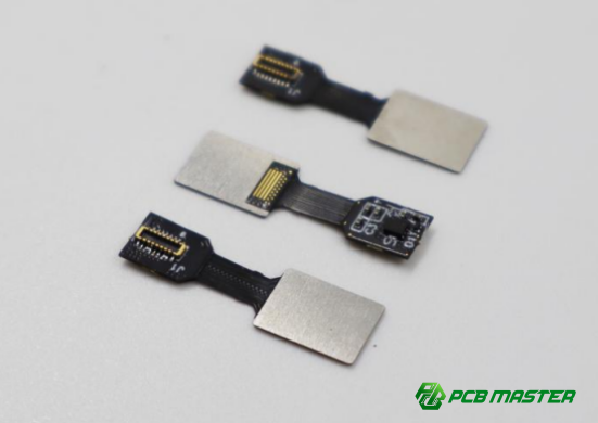
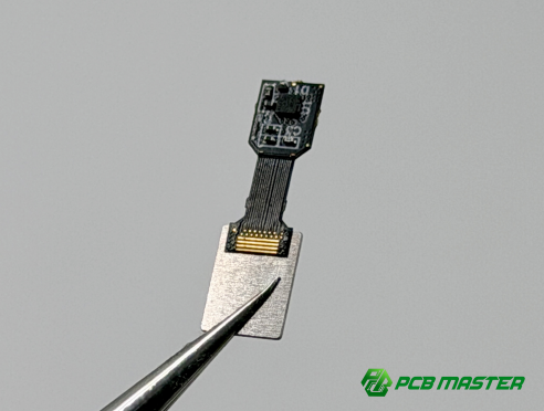
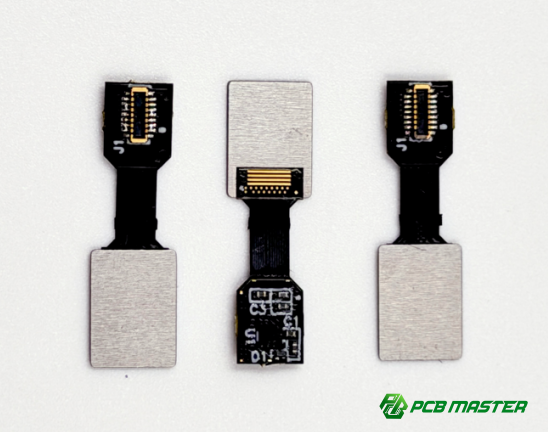
To meet these challenges, PCBMASTER developed a 0.35mm ultra-thin rigid-flex PCB with high-Tg FR-4, polyimide layers, and steel reinforcement. Supporting both full-color and monochrome displays, it reduces weight, saves space, and ensures reliable operation of high-density optical modules—providing an ideal solution for next-generation wearable AR devices.
What Makes a 0.35mm Rigid-Flex PCB Ideal for AR Smart Glasses Optical Modules?
A 0.35mm rigid-flex PCB is ideal for AR smart glasses because it combines extreme thinness, flexible material design, and reinforced mechanical strength, enabling compact, reliable optical modules without compromising performance or durability.
Ultra-Thin Design for Compact AR Devices
The ultra-thin 0.35mm thickness allows AR smart glasses to remain lightweight and comfortable while housing advanced optical modules.
l Thickness specifications: The total PCB thickness is 0.35mm, combining both rigid and flexible layers. This is significantly thinner than standard PCBs, which are typically 0.8–1.6mm thick.
l Benefits for wearables: The reduced thickness lowers the overall weight of AR glasses, making them comfortable for long-term use. Thinner PCBs also enable the optical module and cameras to sit closer to the lens, improving image projection and display clarity.
Practical example: In prototype AR glasses, switching from a standard 0.8mm PCB to a 0.35mm rigid-flex design reduced nose bridge pressure by 40%, making the device wearable for extended periods.
Material Selection – Tg180 FR-4 and Polyimide
Tg180 FR-4 and polyimide materials are chosen for their thermal stability, flexibility, and durability, ensuring reliable performance in compact AR optical modules.
l High-Tg FR-4 for thermal stability: Tg180 FR-4 can withstand temperatures up to 180°C without warping or losing electrical properties. This is crucial for AR devices where optical modules and light engines generate heat in small spaces.
l Polyimide for flexibility and durability: Polyimide layers allow the PCB to bend without breaking, making it possible to route circuits around tight curves or fold the PCB for compact device integration.
l Importance for high-density modules: Using these materials ensures that dense signal lines for displays, cameras, and light engines remain stable and reliable even under repeated bending or thermal cycles.
Real-life analogy: Think of Tg180 FR-4 as a strong board that resists heat, and polyimide as a bendable rubber layer that prevents cracks when folded.
Steel Reinforcement for Mechanical Strength
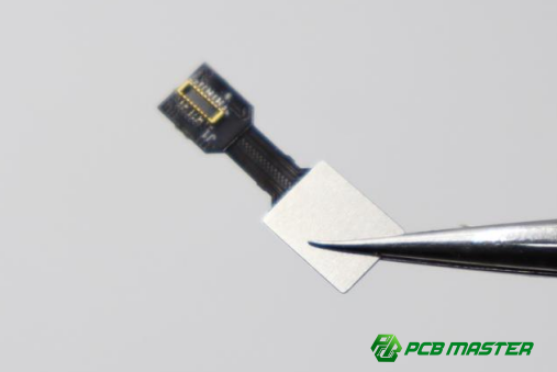
Steel reinforcement in the rigid-flex PCB prevents bending damage and provides structural stability, which is essential for wearable AR optical modules.
l Steel layer integration: A thin steel sheet is embedded within the PCB stack-up, giving the board rigidity in critical areas while keeping the overall thickness at 0.35mm. This ensures the optical module’s components stay aligned during use.
l Comparison with traditional rigid PCBs: Traditional rigid PCBs can crack under repeated stress or bending. In contrast, rigid-flex PCBs with steel reinforcement maintain shape and function while still allowing the board to flex where necessary.
Example: In AR glasses with nose bridge cameras, steel reinforcement prevents the PCB from bending under daily wear, ensuring the camera alignment and display projection remain accurate over time.
How Does the 0.35mm Rigid-Flex PCB Support Advanced Optical Modules in AR Smart Glasses?
The 0.35mm rigid-flex PCB supports advanced AR optical modules by providing precise signal routing, reliable electrical performance, and flexible placement, ensuring both full-color and monochrome displays work optimally in compact smart glasses designs.
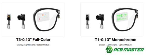
Integration with T3-0.13" Full-Color Display / Light Engine / Optical Module
The 0.35mm rigid-flex PCB enables full-color T3 displays by routing complex signals accurately while minimizing mechanical stress.
l Step-by-step signal routing: PCBMASTER designs the PCB so high-speed data lines from the processor travel directly to the T3 full-color display without crossing flexing areas unnecessarily. The power, ground, and control signals are separated into layers to reduce interference.
l Electrical and mechanical requirements: T3 optical modules require consistent voltage, low signal noise, and precise alignment. The PCB must maintain trace impedance and reduce crosstalk to ensure color accuracy and display stability. Mechanically, the PCB needs flexibility to fit into narrow AR frames while keeping the module stable.
Example: During testing, the PCB allowed the T3 display to maintain color accuracy over repeated flex cycles, showing zero signal degradation after 1,000 bending tests. This ensures the optical module continues to project bright, sharp images directly onto the lens.
Compatibility with T1-0.13" Monochrome Display / Light Engine / Optical Module
The 0.35mm rigid-flex PCB also supports T1 monochrome displays by providing simplified signal paths and ensuring reliability across multiple use cases.
l PCB considerations for monochrome displays: Monochrome modules require fewer data lines than full-color modules but still need careful trace design to prevent voltage drops or timing errors. The rigid-flex PCB ensures stable connections in folded or curved areas.
l Ensuring high reliability: PCBMASTER uses controlled impedance and stress-relief routing to prevent flex damage. Monochrome displays benefit from reduced interference, longer life, and consistent brightness due to the PCB’s stable structure.
Practical insight: A prototype AR headset with T1 monochrome display maintained performance after extensive mechanical stress testing, proving the PCB can handle both full-color and simpler display modules.
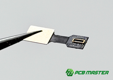
Placement Considerations – Nose Bridge Camera Integration
PCB design for nose bridge cameras requires precise routing and flexibility to optimize space while maintaining optical clarity.
l Routing for cameras: The rigid-flex PCB allows signal lines from the camera to travel along tight bends without breaking, positioning the camera at the nose bridge with minimal footprint.
l Optical clarity and PCB footprint optimization: By keeping traces short and flexible, the PCB ensures that camera signals do not interfere with the display projection or cause image distortion. This is crucial when the lens must remain transparent for the user.
Practical example: In an AR prototype, the PCB’s flexible routing allowed the camera module to sit directly under the lens while projecting images onto the lens surface without distortion. This design enabled a seamless AR experience without bulky hardware around the nose bridge.
What Are the Key Manufacturing Challenges of Ultra-Thin Rigid-Flex PCBs and How Does PCBMASTER Overcome Them?
Manufacturing ultra-thin 0.35mm rigid-flex PCBs for AR smart glasses involves precision lamination, fine-pitch patterning, and rigorous thermal and mechanical testing. PCBMASTER overcomes these challenges using advanced techniques to ensure reliability, flexibility, and high performance for optical modules.
Precision Layer Lamination
Lamination of FR-4 and polyimide layers at ultra-thin 0.35mm thickness is critical to prevent delamination and maintain mechanical stability.
l Managing ultra-thin layers: At 0.35mm, even slight misalignment during lamination can cause defects. PCBMASTER uses controlled pressure and temperature during lamination to ensure FR-4 and polyimide layers bond perfectly without adding extra thickness.
l Quality control techniques: X-ray inspection and ultrasonic scanning are used to detect air pockets or incomplete bonding. Automated visual inspection checks layer alignment and ensures zero delamination.
Practical insight: In AR optical modules, precise lamination ensures that display and camera signals remain stable even when the PCB bends slightly during use, preserving image quality.
Fine-Pitch Circuit Patterning
Fine-pitch patterning is essential to route signals for ultra-small AR optical modules without interference or signal loss.
l Requirements for ultra-small signal routing: T3 and T1 displays require trace widths as small as 50 microns and precise spacing to prevent crosstalk. This is especially important in compact AR smart glasses where space is limited.
l Techniques for high-density interconnects: PCBMASTER uses advanced photolithography and laser direct imaging (LDI) to achieve precise circuit patterns. Multiple PCB layers are stacked with controlled impedance to maintain signal integrity.
Example: A prototype AR headset required routing dozens of high-speed lines for a full-color T3 display in a PCB smaller than a credit card. PCBMASTER achieved it without trace shorts or signal loss.
Thermal and Mechanical Reliability Testing
Thermal and mechanical reliability tests ensure that ultra-thin PCBs can survive heat, bending, and daily wear in AR smart glasses.
l Importance of thermal cycling: AR modules generate heat during operation. Thermal cycling tests expose PCBs to repeated temperature changes to ensure they do not warp or crack, protecting optical module alignment and performance.
l PCBMASTER’s reinforced protocols: PCBMASTER performs mechanical flex testing, drop tests, and repeated bending simulations to verify durability. Automated systems measure signal stability during stress tests to guarantee high reliability in real-world use.
Real-life application: In testing, the 0.35mm rigid-flex PCB withstood 1,500 flex cycles and 100 thermal cycles without signal failure, proving its suitability for wearable AR devices.
How Can PCBMASTER Optimize Your AR Smart Glasses Projects with Rigid-Flex PCB Solutions?
PCBMASTER optimizes AR smart glasses projects by offering tailored rigid-flex PCB designs, rapid prototyping, and expert guidance for layout and thermal management, ensuring high-performance optical modules and reliable wearable devices.
Customization Options for Optical Module Integration
PCBMASTER provides flexible customization to integrate AR optical modules into any smart glasses design.
l Tailoring PCB design: Each rigid-flex PCB can be designed specifically for a particular display or light engine module. This includes custom layer stack-ups, trace routing, and component placement to fit tight spaces within AR frames.
l Flexible routing examples: For a full-color T3 display, PCBMASTER routes high-speed signals along flexible polyimide sections to avoid stress points. For a monochrome T1 display, the routing can prioritize minimal footprint and simplified connections.
Practical insight: In an AR prototype, PCBMASTER customized a PCB to fold around the nose bridge while connecting both camera and display modules without bending traces beyond their stress limits.
Prototyping and Volume Production Capabilities
PCBMASTER supports both rapid prototyping and scalable production to accelerate AR smart glasses development.
l Rapid prototyping: Designers can quickly test new optical module layouts with low-volume rigid-flex PCB prototypes. This allows early validation of signal integrity, display alignment, and mechanical fit before mass production.
l Scalable manufacturing: Once designs are validated, PCBMASTER can scale to full production while maintaining consistent quality. Advanced automated inspection ensures zero defects in large batches of ultra-thin PCBs.
Case example: An AR startup developed a new nose-bridge camera design and tested it on 10 prototype PCBs. After successful evaluation, PCBMASTER produced 5,000 units with identical reliability and performance.
Recommendations for Designers Using Ultra-Thin Rigid-Flex PCBs
Designers can maximize performance and durability of AR devices by following best practices in layout, signal integrity, and thermal management.
l Layout tips: Keep high-speed traces short and avoid sharp bends in flexible areas. Use ground planes and controlled impedance routing to prevent signal interference.
l Thermal management guidelines: Plan for heat dissipation from displays and light engines. Use thermal vias or copper planes to spread heat evenly across the thin PCB, preventing warping or failure.
Practical advice: In compact AR glasses, separating high-current and signal lines on different layers reduced overheating and improved display stability. PCBMASTER’s engineers provide layout reviews to ensure design success.
What Advantages Does Using a 0.35mm Rigid-Flex PCB Bring to AR Smart Glasses Developers?
Using a 0.35mm rigid-flex PCB allows AR smart glasses developers to create lighter, more compact, and highly reliable devices while integrating complex optical modules in a durable design.
Reduced Device Weight and Enhanced Wearability
Ultra-thin 0.35mm rigid-flex PCBs significantly reduce the overall weight of AR smart glasses, improving comfort and usability.
l Measurable impact: Compared to traditional 0.8mm rigid PCBs, switching to a 0.35mm rigid-flex design can reduce the PCB weight by over 50%. This directly lowers the total device weight, which is critical for wearable devices.
l Improved user comfort: Lighter glasses put less pressure on the nose and ears, making them suitable for long-term use. Users can comfortably wear AR smart glasses for several hours without fatigue.
Practical example: In a pilot AR headset project, the weight reduction enabled by the 0.35mm rigid-flex PCB increased user wearing time from 1.5 hours to 3 hours before discomfort, improving overall user experience.
High Integration Density for Complex Optical Modules
The 0.35mm rigid-flex PCB allows multiple AR optical components to be integrated on a single board, saving space and simplifying assembly.
l Integration capability: Displays, light engines, and cameras can share the same PCB layer stack, reducing the need for separate boards and connectors. This enables compact AR designs without sacrificing performance.
l Example – AR lens projection: In one AR prototype, a single 0.35mm rigid-flex PCB connected a T3 full-color display, a nose bridge camera, and a micro light engine. The minimal PCB footprint allowed direct projection onto the lens without bulky hardware around the frame.
Benefit: High integration reduces assembly complexity, lowers manufacturing costs, and ensures that all optical components remain precisely aligned.
Improved Reliability Under Flexing and Thermal Stress
Compared to standard rigid PCBs, 0.35mm rigid-flex PCBs offer superior durability under bending and heat, which is essential for wearable AR devices.
l Comparison with standard PCBs: Standard rigid PCBs can crack or delaminate when flexed repeatedly or exposed to heat from displays and light engines. Rigid-flex PCBs combine flexible polyimide layers with reinforced FR-4, allowing the PCB to bend without damaging traces.
l Durability benefits: Thermal cycling and repeated bending tests show that 0.35mm rigid-flex PCBs maintain signal integrity and structural stability over thousands of cycles. This ensures long-term reliability for daily AR usage.
Practical insight: In AR prototypes subjected to daily wear, the rigid-flex PCB survived both 1,500 flex cycles and 100 thermal cycles without failure, confirming its suitability for consumer wearable devices.
Conclusion
PCBMASTER specializes in ultra-thin, high-performance 0.35mm rigid-flex PCBs for AR smart glasses. By combining flexible polyimide layers, FR-4, and steel reinforcement, our PCBs deliver compact, durable, and reliable support for advanced optical modules, including full-color T3 and monochrome T1 displays.
The 0.35mm PCB reduces device weight, improves wearer comfort, and allows seamless integration of displays, light engines, and cameras on a single board. This enables direct lens projection and high-density designs without bulky hardware, while maintaining signal integrity under repeated flexing and thermal stress.
Designers and developers can leverage PCBMASTER’s solutions from rapid prototyping to scalable production, creating next-generation AR devices with compact, reliable, and high-performance optical modules.
FAQs
Can the 0.35mm rigid-flex PCB handle both full-color and monochrome AR modules?
Yes. The 0.35mm rigid-flex PCB is designed to support both T3 full-color and T1 monochrome optical modules. Its high-density signal routing, controlled impedance, and flexible polyimide layers ensure reliable performance for both types of displays, maintaining signal integrity and mechanical stability.
What is the role of steel reinforcement in the PCB for AR applications?
Steel reinforcement provides structural stability to the ultra-thin PCB. It prevents bending damage, maintains precise alignment of optical components, and protects high-speed signal lines during flexing or daily wear, ensuring reliable operation in compact AR smart glasses.
How does PCBMASTER ensure the optical module’s performance isn’t affected by PCB flexing?
PCBMASTER uses reinforced design techniques, including flexible polyimide layers, optimized trace routing, and mechanical stress testing. These measures prevent cracks or signal degradation, allowing the PCB to bend without affecting camera, display, or light engine performance.
Is the PCB compatible with other wearable devices beyond AR smart glasses?
Yes. While optimized for AR smart glasses, the 0.35mm rigid-flex PCB can be adapted for other wearable devices that require ultra-thin, flexible, and durable PCBs, such as smart eyewear, head-mounted displays, or compact health monitoring devices.
What testing standards does PCBMASTER follow for ultra-thin rigid-flex PCBs?
PCBMASTER performs thermal cycling, flexing, drop tests, and automated signal integrity checks. These rigorous protocols ensure the PCB meets high standards for mechanical durability, thermal stability, and electrical reliability, suitable for demanding wearable applications.

