


Understanding Printed Circuit Board Transformers: A Complete Overview
In the intricate world of electronics, tiny components often carry the heaviest responsibilities. Among them, the printed circuit board transformer quietly powers devices, channels signals, and maintains stability across countless applications. Though its presence is subtle, its role is pivotal—shaping performance, efficiency, and safety in ways that are easy to overlook yet impossible to ignore. Understanding how these compact devices operate reveals not only the mechanics of modern circuits but also the ingenuity behind the electronics that surround us every day.
Introduction to Printed Circuit Board (PCB) Transformers
What is a PCB Transformer?
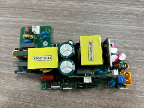
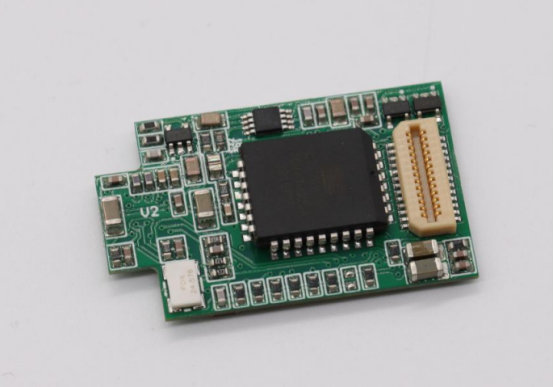
A printed circuit board (PCB) transformer is an electronic component designed to transfer electrical energy between two or more circuits through electromagnetic induction, while being mounted directly onto a PCB. Unlike traditional wire-wound transformers, which are often bulky and separate from the circuit board, PCB transformers integrate compactly into the board layout. This integration allows them to occupy minimal space, making them ideal for modern electronic devices where size constraints are critical.
PCB transformers are used in a variety of applications. In power supply circuits, they step voltage up or down to match the needs of different components. In communication circuits, they provide signal isolation to prevent interference and maintain signal integrity. They are also common in LED drivers, audio equipment, and microcontroller circuits, where precise voltage control and compact design are essential.
The main distinction between PCB transformers and conventional transformers lies in their construction and mounting method. While conventional transformers use large copper wire coils wound around a magnetic core, PCB transformers often use copper traces directly on the PCB for windings or a combination of small coils and PCB traces. This difference allows PCB transformers to be lighter, thinner, and more easily integrated into automated manufacturing processes, though they may have lower power ratings compared to large traditional transformers.
Importance in Modern Electronics
PCB transformers play a critical role in modern electronics by performing three key functions: power regulation, signal isolation, and voltage conversion. Power regulation ensures that components receive a stable voltage, protecting sensitive electronics from fluctuations. Signal isolation prevents electrical noise or faults from propagating through connected circuits, which is especially important in communication and industrial applications. Voltage conversion allows devices to operate with varying power levels, such as converting a 12V supply down to 5V for low-power components.
One of the most significant advantages of PCB transformers is their compact size. By integrating the transformer directly onto the PCB, designers can save valuable board space and reduce overall device footprint. They are also highly reliable, with fewer mechanical connections that could fail over time. Integration with PCB layouts further allows for optimized thermal management and efficient routing of traces, which contributes to overall system performance.
In real-world applications, PCB transformers are found in power supplies for laptops, desktop computers, and small electronic devices. They are essential components in LED driver circuits, ensuring consistent light output while isolating sensitive control circuitry. Audio amplifiers and signal processing equipment also rely on PCB transformers for clean and stable signal transmission. By enabling precise voltage control, isolation, and compact integration, PCB transformers help modern electronics achieve both high performance and reliability.
Core Components of PCB Transformers
Magnetic Core
The magnetic core is the heart of a PCB transformer. It provides a controlled path for magnetic flux, enabling efficient energy transfer between the primary and secondary windings. Core materials significantly influence the transformer’s efficiency, frequency response, and size.
There are three main types of cores used in PCB transformers: ferrite, laminated, and toroidal. Ferrite cores are made from iron oxide and other metallic elements, offering low electrical conductivity and excellent performance at high frequencies. Laminated cores are constructed by stacking thin sheets of steel, reducing eddy current losses and improving efficiency at low to medium frequencies. Toroidal cores, shaped like a donut, provide minimal magnetic leakage and high efficiency in compact designs.
For example, in high-frequency switching power supplies, ferrite cores are often preferred because their low core losses allow the transformer to operate efficiently at tens or hundreds of kilohertz. Laminated cores, on the other hand, are more suitable for low-frequency applications, such as 50–60 Hz AC power transformers, where mechanical strength and low-cost materials are more important than high-frequency performance.
Windings
Windings are conductive coils wrapped around the core to facilitate electromagnetic induction. PCB transformers typically have primary windings, which receive input voltage, and secondary windings, which deliver transformed voltage to the circuit. The structure and arrangement of windings directly affect transformer performance, including voltage regulation, leakage inductance, and efficiency.
PCB windings can be formed using copper traces etched directly onto the board or using fine wire coils soldered to pads. Copper trace windings are ideal for compact, low-power transformers, while wire-wound designs can handle higher currents and voltages.
The voltage transformation ratio depends on the turns ratio between primary and secondary windings. For instance, if the primary winding has 100 turns and the secondary has 50 turns, the transformer reduces voltage by half. Step-by-step, the input voltage is applied to the primary winding, generating a magnetic flux in the core, which induces a voltage in the secondary winding according to the ratio of turns. This principle allows designers to precisely match transformer output to circuit requirements.
Insulation and Safety Features
Insulation in PCB transformers prevents electrical shorts and ensures safe operation between windings and surrounding components. Common insulation materials include enamel coatings on wire, polymer films, and reinforced epoxy resins. These materials help maintain dielectric strength and resist heat, moisture, and mechanical stress.
Compliance with safety standards such as UL (Underwriters Laboratories) and IEC (International Electrotechnical Commission) is essential for certified transformers. These standards define requirements for isolation, voltage withstand, and creepage distances between conductive parts.
Key design considerations include selecting appropriate insulation materials, maintaining adequate spacing between windings, and accounting for voltage surges. For example, in a 12V-to-5V PCB transformer used in a USB charger, the insulation must prevent high-voltage spikes from reaching the low-voltage circuit while remaining thin enough to fit within a compact PCB layout.
How PCB Transformers Work
Basic Operating Principle
A PCB transformer operates on the principle of electromagnetic induction, where a changing current in the primary winding generates a magnetic flux in the core, which induces a voltage in the secondary winding. This process allows electrical energy to be transferred from one circuit to another without direct electrical contact.
The transformer’s behavior is influenced by frequency. High-frequency PCB transformers, common in switching power supplies, require ferrite cores to minimize core losses. Low-frequency designs, like AC power transformers, use laminated steel cores to reduce eddy current losses. By controlling the number of turns in the primary and secondary windings, designers can adjust voltage levels precisely.
For example, if a primary winding is connected to a 12V input and has 120 turns, while the secondary winding has 60 turns, the output voltage will be half of the input (6V), following the simple formula:
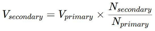
This step-by-step voltage conversion is fundamental to designing reliable circuits.
Key Performance Metrics
Several metrics define the performance of a PCB transformer:
Voltage ratio: Determines the output voltage relative to the input.
Current rating: Maximum current the transformer can safely carry.
Efficiency: Ratio of output power to input power, influenced by core and winding losses.
Leakage inductance and parasitic capacitance: Small undesired effects that can impact high-speed signals and voltage regulation.
For example, in a high-speed digital circuit, excessive leakage inductance can cause voltage spikes. Designers often reduce this by optimizing winding placement and using appropriate core materials.
Types of PCB Transformers by Function
PCB transformers can be categorized based on their function:
Signal transformers: Isolate and transfer signals without affecting voltage levels significantly. Common in audio and communication circuits.
Power transformers: Convert voltage levels to supply power to various parts of a device.
Isolation transformers: Separate circuits to prevent electrical noise and enhance safety, often used in medical or industrial equipment.
A comparison helps illustrate their use: a signal transformer in an audio amplifier ensures clean transmission of sound without distortion, while a power transformer in a laptop charger steps down mains voltage to a safe, usable level.
Design Considerations for PCB Transformers
PCB Layout Best Practices
The layout of a PCB transformer is critical for performance and reliability. Proper placement of the windings and magnetic core minimizes electromagnetic interference (EMI) and ensures efficient energy transfer. Designers must calculate trace width and spacing to handle the expected current while preventing overheating or short circuits.
For example, in a 5V USB power circuit, wider copper traces are used for the primary winding to handle higher currents, while secondary traces can be narrower if the current is lower. Routing the traces in tight, symmetrical patterns can also reduce leakage inductance and EMI, improving voltage stability.
Thermal Management
PCB transformers generate heat due to core losses and resistance in the windings. Efficient thermal management extends transformer lifespan and maintains stable operation. Designers often use copper pours, thermal vias, or heat sinks to dissipate heat.
A practical example: in an LED driver circuit, a small PCB transformer may become warm under continuous operation. Adding thermal vias beneath the windings allows heat to transfer to the board’s other layers, preventing overheating without increasing the device’s size.
Design Challenges
Designing PCB transformers involves balancing multiple factors: miniaturization, efficiency, and electrical performance. Reducing size can increase winding resistance and leakage inductance, while increasing efficiency may require more layers or larger cores.
Step-by-step, designers address these challenges by:
1. Selecting a core material suitable for the operating frequency.
2. Calculating the optimal turns ratio for voltage conversion.
3. Routing windings to minimize EMI and parasitic effects.
4. Adding insulation and thermal management features.
For instance, in a high-frequency switching power supply, a designer might choose a ferrite core, optimize the winding layout, and add copper fills for cooling, achieving both compact size and high efficiency.
Applications of PCB Transformers
Consumer Electronics
PCB transformers are widely used in consumer electronics to provide compact and reliable voltage conversion. They appear in laptops, smartphones, tablets, and televisions, where space is limited and precise voltage regulation is essential. In LED lighting systems, PCB transformers ensure consistent brightness and protect the circuit from voltage fluctuations.
For example, in a smartphone charger, a PCB transformer steps down the high-voltage AC input from the wall outlet to a safe low-voltage DC output, while also isolating the device from electrical hazards. This integration enables chargers to remain small, lightweight, and efficient.
Industrial Applications
In industrial equipment, PCB transformers serve critical roles in motor drives, automation systems, and instrumentation circuits. They provide voltage conversion and signal isolation in environments with high electrical noise.
For instance, in a programmable logic controller (PLC), a PCB transformer isolates sensitive control circuits from high-voltage power circuits. This prevents interference and protects expensive components, ensuring reliable operation in industrial settings.
High-frequency switching applications, such as power inverters or variable-frequency drives, also rely on ferrite-core PCB transformers for efficient energy transfer without excessive heat generation.
Emerging Applications
As electronics become smaller and more integrated, PCB transformers are finding roles in IoT devices, wearable electronics, and renewable energy systems. Embedded transformers in multilayer PCBs reduce device size while maintaining electrical performance.
For example, in a solar micro-inverter, a PCB transformer converts DC power from photovoltaic panels to AC while isolating the system for safety. In IoT sensors, PCB transformers enable low-power voltage regulation within tiny form factors, allowing devices to operate reliably over extended periods.
Troubleshooting and Maintenance
Common Issues
PCB transformers can encounter several common issues during operation. Overheating may result from excessive current, poor thermal management, or core losses. Short circuits can occur due to damaged insulation, soldering defects, or moisture ingress. Voltage fluctuations may indicate winding damage, turns ratio errors, or core saturation.
For example, in an LED driver circuit, flickering lights can often be traced to a partially damaged PCB transformer where one winding has lost continuity or insulation has degraded, causing inconsistent voltage delivery.
Diagnostic Techniques
Diagnosing PCB transformer issues requires simple but systematic testing. Using a multimeter, one can check for continuity and resistance in the windings to detect open or shorted turns. An LCR meter can measure inductance and identify deviations from expected values, indicating potential core or winding problems.
Step-by-step, a basic diagnostic process includes:
1. Power off the device and visually inspect the transformer for burn marks or discoloration.
2. Measure resistance across the primary and secondary windings to check continuity.
3. Verify output voltage under controlled conditions to confirm proper voltage transformation.
4. Compare measurements with design specifications to identify discrepancies.
Replacement and Upgrades
When a PCB transformer fails, selecting a suitable replacement is critical. Factors include voltage rating, current rating, turns ratio, and physical size. Upgrading to a higher-quality transformer may improve performance, reduce heat generation, and extend device lifespan.
For instance, replacing a low-frequency laminated core transformer with a high-frequency ferrite-core PCB transformer in a switching power supply can improve efficiency and allow for a smaller board footprint. Additionally, revisiting layout and thermal management can prevent recurrence of overheating or electrical noise issues.
Future Trends in PCB Transformer Technology
Miniaturization and High-Frequency Designs
One of the most significant trends in PCB transformer technology is miniaturization. Advances in core materials and winding techniques allow transformers to become smaller without sacrificing performance. High-frequency designs, enabled by ferrite cores and precise PCB winding patterns, reduce core size while maintaining efficient energy transfer.
For example, modern smartphone chargers use high-frequency PCB transformers that are tiny enough to fit within slim casings yet deliver stable voltage outputs efficiently. High-frequency operation also minimizes energy losses and heat generation, which is crucial for compact, portable devices.
Integration with Advanced PCB Technologies
PCB transformers are increasingly being embedded directly into multilayer PCBs. Embedded transformers reduce the need for external components, save board space, and improve signal integrity. This integration allows more complex circuits to be built within a smaller footprint.
For instance, in IoT devices or wearable electronics, embedded PCB transformers supply isolated power to sensitive circuits while keeping the device compact and lightweight. Compared to traditional discrete transformers, embedded designs reduce assembly complexity and improve mechanical reliability.
Sustainability and Energy Efficiency
Energy efficiency and environmental impact are becoming central considerations. PCB transformers are being designed with eco-friendly materials, lower core losses, and improved thermal performance. Regulatory standards now often require transformers to meet strict energy efficiency and safety criteria.
A practical example is the design of LED driver circuits: modern PCB transformers are optimized to reduce standby power consumption, lower heat output, and use recyclable materials. This approach not only benefits device performance but also supports global sustainability efforts in electronics manufacturing.
Conclusion
PCB transformers may be small components, but their impact on modern electronics is immense. From enabling precise voltage conversion to providing reliable signal isolation, they play a pivotal role in devices ranging from consumer electronics to industrial systems. As technology continues to evolve toward miniaturization, high-frequency operation, and energy efficiency, the demand for expertly designed PCB transformers will only grow. At PCBMASTER, we specialize in high-performance PCB solutions, helping engineers and designers bring compact, reliable, and innovative electronic designs to life.
FAQs
How do PCB transformers differ from traditional wire-wound transformers?
PCB transformers are designed to be integrated directly onto a printed circuit board, using copper traces or small wire coils for their windings. Traditional wire-wound transformers, by contrast, are often larger, standalone components with bulky wire coils wrapped around a magnetic core. PCB transformers are more compact, lightweight, and suitable for automated manufacturing, while traditional transformers typically handle higher power levels but occupy more space.
What factors determine the efficiency of a PCB transformer?
Efficiency depends on several key factors: the type and quality of the magnetic core, the winding material and layout, and the operating frequency. Low core losses, minimal winding resistance, and optimized turns ratio all contribute to higher efficiency. Proper thermal management also helps maintain performance, as excessive heat can increase energy losses.
Can PCB transformers handle high current applications safely?
Yes, but within limits. High-current PCB transformers require careful trace width design, adequate copper thickness, and effective thermal management to prevent overheating. For very high currents, wire-wound PCB transformers are often used instead of purely etched copper traces. Designers must also ensure insulation and spacing meet safety standards to handle the intended load reliably.
How is EMI minimized in PCB transformer designs?
Electromagnetic interference (EMI) can be reduced by careful winding placement, symmetrical trace routing, and shielding. Using toroidal cores or ferrite cores optimized for high frequencies also helps contain magnetic flux. Proper grounding and separation between primary and secondary circuits further reduce noise and improve signal integrity.
What are the most common failure modes of PCB transformers?
Common failures include overheating due to excessive current or poor thermal design, short circuits from damaged insulation or soldering defects, and core saturation, which can cause voltage instability. Winding damage or incorrect turns ratios may also lead to malfunction. Regular inspection, correct design, and quality materials help minimize these risks.

