


Printed Circuit Board Switches: Types, Features, and Best Practices
Printed circuit board (PCB) switches are small but essential components that control the flow of electricity in nearly every electronic device. From the tactile buttons on a keyboard to sophisticated touch-sensitive panels in modern gadgets, these switches determine how users interact with technology. Choosing the right PCB switch can impact device performance, reliability, and lifespan, making it a critical decision for engineers, designers, and electronics enthusiasts alike.
Understanding the different types of PCB switches, their key features, and practical best practices ensures the right solution is selected for any project—whether it’s a prototype, a high-volume product, or a compact wearable device.
Understanding PCB Switches
Definition of PCB Switches
A printed circuit board (PCB) switch is an electronic component designed to control the flow of electricity within a circuit. Essentially, it acts as a gate that can open or close a circuit, allowing current to pass or stopping it as needed. PCB switches come in various forms, including mechanical buttons, slide switches, and touch-sensitive capacitive switches, each suited for specific applications.
For example, a tactile push-button on a keyboard PCB completes the circuit when pressed, sending a signal to the device, whereas a slide switch on a small appliance may turn a function on or off by maintaining the circuit in a fixed position. These switches are directly mounted on the PCB, making them an integral part of the device’s electronic system.
Importance in Electronics
PCB switches are critical for device functionality, user control, and safety. They allow users to interact with electronic devices, such as powering them on, adjusting settings, or triggering specific functions. Without reliable switches, devices may fail to respond properly, leading to user frustration or even safety hazards.
The importance of PCB switches extends across various audiences:
Electronics designers rely on switches to create intuitive user interfaces.
Engineers consider switch reliability and lifespan when designing circuits for industrial or consumer electronics.
Hobbyists need to understand switch types and behaviors for effective prototyping and DIY electronics projects.
For instance, choosing the wrong type of switch for a high-current application could result in overheating or circuit failure, highlighting the importance of matching switch specifications to the intended function.
Types of Printed Circuit Board Switches
Mechanical Switches
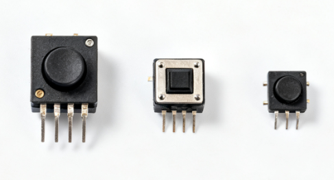
Mechanical switches are the most common type of PCB switch and rely on physical movement to open or close a circuit. Common varieties include tactile switches, push-button switches, and rocker switches.
Example: A tactile push-button on a keyboard PCB completes a circuit when pressed, providing a small “click” or tactile feedback.
Pros: High durability, clear tactile feel, and precise actuation force.
Cons: Larger size compared to membrane switches and mechanical wear over time.
Mechanical switches are ideal for applications where user feedback and reliability are important, such as keyboards, control panels, and industrial devices.
Slide and DIP Switches
Slide switches allow simple ON/OFF control by sliding the actuator to open or close the circuit. They are compact, easy to use, and suitable for low-power applications.
DIP (Dual In-line Package) switches are often used to set configurations or adjust settings in circuits. Each switch in the DIP can represent an individual option, such as addressing a device on a network or enabling a feature.
These switches are typically chosen for low-frequency, low-current applications where simple user adjustments are required.
Membrane and Capacitive Switches
Membrane switches are thin, flexible, and lightweight, making them suitable for modern electronics such as calculators, remote controls, and medical devices. They consist of several layers, including a flexible circuit, spacer, and actuator layer.
Capacitive switches detect touch using changes in capacitance, allowing touch-sensitive input without mechanical movement. These switches are common in smartphones, tablets, and touch panels.
Advantages: Slim design, water resistance, and silent operation.
Limitations: Less tactile feedback compared to mechanical switches.
Rotary and Rotary Encoder Switches
Rotary switches and rotary encoders provide rotational input, often used for volume control, menu navigation, or setting adjustments.
Rotary switches: Rotate to select one position among several options.
Rotary encoders: Provide continuous or incremental rotational signals, allowing for precise adjustments.
These switches are widely used in audio equipment, instrumentation, and control systems.
Comparison Overview
A simple comparison helps summarize the key differences:
| Switch Type | Typical Use Case | Durability | Cost | Notes |
|---|---|---|---|---|
| Mechanical | Keyboards, panels | High | Medium | Tactile feedback, larger footprint |
| Slide | Simple ON/OFF control | Medium | Low | Compact, easy to use |
| DIP | Configuration settings | Medium | Low | Multiple switches per package |
Membrane | Remote controls, medical | Medium | Low | Flexible, water-resistant |
Capacitive | Touch panels, smartphones | High | Medium | Touch-sensitive, no moving parts |
Rotary / Encoder | Volume, menu control | High | Medium | Rotational input, precise adjustment |
Key Features to Consider in PCB Switches
Electrical Ratings
One of the most important factors when selecting a PCB switch is its electrical rating. This includes:
Voltage capacity – the maximum voltage the switch can safely handle.
Current capacity – the maximum current the switch can conduct without overheating.
Contact resistance – the resistance between contacts when the switch is closed, which affects signal quality.
For example, a switch rated for 12V and 100mA is suitable for low-power signal circuits but would be unsafe in a high-current application like motor control. Choosing the right electrical rating prevents failures and ensures reliable performance.
Mechanical Durability
Mechanical durability defines how long a switch can operate effectively. Key parameters include:
Actuation cycles – the number of times the switch can be pressed or activated before failure.
Travel distance – how far the actuator moves during operation, affecting user feel.
Tactile feedback – the “click” or resistance felt when the switch is pressed.
For instance, a tactile push-button designed for 1 million actuation cycles is ideal for keyboards or control panels, while a switch with only 50,000 cycles may be sufficient for occasional use.
Mounting Type
PCB switches come in two primary mounting styles:
Through-hole switches – leads pass through the PCB and are soldered on the opposite side. Offers stronger mechanical stability, suitable for heavier or high-stress components.
Surface-mount (SMT) switches – soldered directly onto the PCB surface. Allows for compact designs and high-density layouts, but may require precise placement and soldering techniques.
Selecting the right mounting type ensures mechanical reliability and compatibility with PCB design.
Environmental Resistance
Switches must withstand the conditions in which they operate:
Temperature range – ensure the switch functions correctly in expected operating temperatures.
Moisture and dust protection – IP ratings indicate protection against water and dust ingress.
Chemical or vibration resistance – critical in industrial or automotive applications.
For example, an IP67-rated membrane switch can survive outdoor or wet environments without performance degradation.
Size and Form Factor
The physical dimensions of a switch impact PCB layout and device design:
Compact switches are essential for high-density PCBs in portable devices.
Larger switches may offer better tactile feedback or easier handling in industrial controls.
Balancing size, usability, and compatibility with the PCB design ensures both functional and ergonomic performance.
Best Practices for Selecting PCB Switches
Match Switch Type to Application
Selecting the appropriate PCB switch type for your application is crucial. Different switches are designed for specific use cases:
Tactile switches provide clear feedback and are ideal for keyboards or control panels.
Slide switches work well for simple ON/OFF operations in low-power circuits.
Rotary or rotary encoder switches are suitable for volume control, menu navigation, or adjustable settings.
Matching the switch type to the function ensures reliable operation and user satisfaction.
Consider Lifespan and Reliability
Assess the mechanical durability and expected lifespan of switches before selection:
Evaluate actuation cycles – how many times the switch can be reliably used.
Analyze wear patterns to predict potential failures, especially in high-use applications.
For example, a tactile switch rated for 1 million cycles is ideal for devices that experience frequent user interaction, while low-use settings may only require a switch rated for tens of thousands of cycles.
Check Compatibility with PCB Layout
Ensuring the switch fits seamlessly with the PCB design is essential:
Confirm pad design and footprint standards to match the switch.
Consider the soldering method (through-hole vs. surface-mount) to prevent mechanical stress or assembly errors.
Verify spacing and alignment for high-density layouts.
Proper layout compatibility minimizes assembly problems and improves electrical and mechanical reliability.
Evaluate Environmental Conditions
Switches must withstand the conditions of their operating environment:
High humidity or moisture exposure may require IP-rated membrane or sealed switches.
Vibration-prone environments may need mechanically robust or soldered-through switches.
Extreme temperature ranges must match the switch’s rated specifications.
Considering environmental factors ensures long-term reliability and safety in all conditions.
Cost vs. Performance Trade-offs
Balancing quality, durability, and budget is key:
Higher-end switches may offer better actuation cycles, tactile feedback, or environmental resistance but at a higher cost.
Lower-cost switches are suitable for low-use or disposable devices but may have shorter lifespans or less durability.
Selecting a switch involves evaluating total value, not just the initial purchase price, to ensure long-term performance and cost-effectiveness.
Installation and Maintenance Tips
Proper Soldering Techniques
Correct soldering is essential for reliable PCB switch performance. The approach depends on the mounting type:
Through-hole switches: Insert leads into the PCB holes and solder on the opposite side. Ensure even heat distribution to prevent cold solder joints or damage to the switch.
Surface-mount (SMT) switches: Place the switch on the PCB pads and use reflow soldering or careful hand soldering. Avoid excessive heat, which can deform the switch housing or damage internal contacts.
Following proper soldering practices ensures mechanical stability and electrical connectivity.
Preventing Mechanical Stress
Mechanical stress can reduce switch lifespan and cause premature failure. Best practices include:
Avoid bending leads or pushing switches at an angle during assembly.
Do not apply excessive force when mounting or handling the PCB.
Use support tools or fixtures for larger switches to prevent board flexing.
Proper handling maintains switch integrity and consistent performance.
Testing Switch Functionality
Testing is crucial to verify correct operation before final deployment:
Continuity tests: Check that the switch closes and opens the circuit correctly.
Lifecycle tests: Simulate repeated actuation to ensure the switch can withstand its rated number of cycles.
Signal verification: Confirm that electrical signals are transmitted without excessive resistance or noise.
Routine testing reduces the risk of malfunctions and field failures.
Troubleshooting Common Issues
Common switch problems can be identified and corrected with simple troubleshooting:
Debouncing issues: Rapid on/off signals may require software or hardware debounce solutions.
Stuck contacts: Clean or replace switches if mechanical parts are obstructed.
Inconsistent operation: Check solder joints, alignment, and environmental factors such as moisture or dust.
Addressing these issues promptly ensures reliable, long-term switch operation.
Emerging Trends in PCB Switch Technology
Miniaturization and Compact Designs
PCB switches are becoming smaller and more compact to meet the demands of modern electronics. Devices like wearables, portable medical gadgets, and ultra-thin consumer electronics require switches that occupy minimal PCB space without sacrificing reliability. Miniaturized switches allow designers to increase component density, enabling smaller devices with more features.
Touch and Capacitive Interfaces
Traditional mechanical switches are increasingly being replaced by touch-sensitive solutions. Capacitive switches detect changes in capacitance when a user touches the surface, eliminating moving parts and providing a sleeker, silent, and more durable interface. These switches are widely used in smartphones, tablets, home automation panels, and modern appliances.
Advantages: No mechanical wear, resistance to dust and moisture, and flexible design options.
Limitations: Requires precise design and may need software support for debouncing or multi-touch input.
Integration with Smart Devices
PCB switches are now integrating with IoT and smart systems, allowing programmable inputs and remote control. For example, switches in smart home devices can be reprogrammed via apps, or industrial controls can send data to central monitoring systems. This trend enhances connectivity, customization, and real-time monitoring of electronic devices.
Sustainable Materials
Sustainability is becoming a key focus in PCB switch design:
Lead-free contacts reduce environmental impact and meet regulatory standards.
Recyclable plastics and non-toxic materials are used for housings and actuators.
Sustainable switches allow manufacturers to meet green certification requirements while maintaining performance and durability.
Conclusion
Selecting the right PCB switch is crucial for ensuring device performance, reliability, and lifespan. The choice impacts how effectively a device operates, how long it lasts, and how users interact with it. Factors such as electrical ratings, mechanical durability, mounting type, environmental resistance, and form factor must be carefully considered during the design phase to achieve optimal results.
Additionally, keeping an eye on emerging trends—including miniaturization, touch-sensitive interfaces, smart device integration, and sustainable materials—can help designers future-proof their products and stay competitive in the evolving electronics market.
If you have further questions or want to learn more about PCB technology, PCBMASTER, a trusted global PCB supplier, is ready to provide professional guidance and answer any inquiries you may have.
FAQs
1. What is the difference between a tactile switch and a membrane switch?
Tactile switches are mechanical switches that provide physical feedback when pressed, usually a “click” or resistance that signals actuation. They are mounted on a PCB and are ideal for keyboards, control panels, and other applications where tactile feel and durability are important.
Membrane switches are thin, flexible layers that detect pressure without mechanical movement. They are often used in remote controls, medical devices, or appliances, offering a slimmer design and water/dust resistance.
Key differences:
Tactile: Mechanical, robust, higher actuation cycles, more space needed.
Membrane: Non-mechanical, compact, lower tactile feedback, lighter environmental resistance.
2. How do you determine the lifespan of a PCB switch?
The lifespan is typically measured in actuation cycles, which indicates how many times the switch can be pressed or activated before failure.
Factors affecting lifespan:
Mechanical design: Stronger internal springs or contacts last longer.
Electrical load: Higher voltage or current can accelerate wear.
Environmental conditions: Exposure to moisture, dust, vibration, or extreme temperatures can reduce lifespan.
Testing methods: Manufacturers perform lifecycle testing by repeatedly actuating switches under controlled conditions to determine the rated cycle count.
3. Can PCB switches be used in high-voltage applications?
PCB switches can be used in higher-voltage circuits, but only if they are specifically rated for those voltages.
Considerations:
Voltage and current ratings must match or exceed the application requirements.
Contact spacing and insulation must prevent arcing or short circuits.
Environmental factors like humidity can increase the risk of electrical failure.
Example: A switch rated for 250V AC is suitable for mains-level applications, whereas a 12V switch is limited to low-voltage electronics.
4. What are the main causes of switch failure on a PCB?
Mechanical wear: Repeated actuation can degrade springs or contacts.
Electrical overstress: Excessive voltage or current can burn or pit contacts.
Environmental damage: Moisture, dust, or corrosion can prevent proper contact.
Improper soldering or assembly: Cold solder joints, misalignment, or bending leads can create intermittent connections.
Debouncing or software issues: For electronic systems, unfiltered signals can appear as false presses or failures.
5. How do surface-mount switches differ from through-hole switches in assembly?
Through-hole switches:
Through-hole switches have leads that pass through PCB holes and are soldered on the opposite side. This design provides strong mechanical stability, making them ideal for heavy or high-stress components. Assembly of through-hole switches often requires manual insertion or wave soldering to ensure proper connection and durability.
Surface-mount (SMT) switches:
Surface-mount (SMT) switches are soldered directly onto PCB pads on the same side. This design enables smaller form factors and high-density layouts, making them ideal for compact electronic devices. SMT switches are typically assembled using pick-and-place machines and reflow soldering, which require precise placement and careful heat control to ensure reliable connections.
Key difference: Through-hole offers mechanical strength; SMT offers compact size and automated assembly compatibility.

