


The Essential Role of Printed Circuit Board Pins in Electronics
In the world of electronics, even the smallest components can make or break a design. While many focus on microchips, resistors, and capacitors, the humble printed circuit board (PCB) pin often goes unnoticed—yet its role is indispensable. These tiny connectors ensure that power, signals, and data travel seamlessly across your device, affecting everything from reliability to performance. As technology evolves and electronics shrink, the importance of PCB pins has never been greater. Whether you're designing the next big wearable tech or a high-speed communication system, understanding the crucial role of these pins is essential for achieving optimal results.
Introduction to Printed Circuit Board (PCB) Pins
What Are PCB Pins?
Definition and Function of PCB Pins
PCB pins are small metal connectors that play a critical role in linking various components on a printed circuit board (PCB). These pins provide physical and electrical connections between the PCB and external components, such as sensors, microchips, and connectors. Their function is to facilitate the flow of electrical signals, power, and data between different parts of the circuit, ensuring smooth communication and functionality of the device.
How They Connect Components to the Circuit
PCB pins serve as bridges, allowing components to interact with the PCB's traces and pads. For example, when you solder a component onto a PCB, the pins of that component connect to the PCB's conductive traces, which then carry electrical signals or power to other parts of the circuit. These pins are essential for making the necessary physical connections to power supplies, microcontrollers, or any other part of an electronic system that requires a stable, secure link to the board.
Differences Between Pins, Pads, and Vias in PCB Design
While PCB pins are often seen as the key connectors, understanding how they differ from other components like pads and vias is important:
Pins are the external connectors that interface with the device or the external world.
Pads are the areas on the PCB where pins are soldered or mounted. They are the foundation for creating strong electrical connections.
Vias are small holes drilled into the PCB, filled with conductive material, and used to carry signals or power between different layers of a multi-layer PCB.
The main difference lies in their roles: pins connect the circuit to external components, pads serve as the mounting points for those connections, and vias enable vertical communication within the layers of the PCB.
Importance of PCB Pins in Electronic Systems
Critical Role in Signal and Power Transmission
PCB pins ensure the efficient transmission of electrical signals and power throughout the device. For example, in a microprocessor-based system, PCB pins connect the power supply pins of a chip to the PCB’s power traces, while also routing data signals between the processor and other components like memory or sensors. If the pins are of poor quality or improperly positioned, signal integrity can degrade, leading to malfunction or performance issues.
Ensuring Reliable Communication Between Components
Reliable communication between components depends heavily on the integrity of the connections made through PCB pins. These pins must be able to withstand various stresses, including thermal cycling, vibration, and mechanical stress, to ensure long-term functionality. In high-performance devices like smartphones or medical equipment, even small issues in pin connectivity can result in failure or unreliable operation. For example, in a smartphone’s motherboard, pins connecting the processor to the display or battery must be precise to avoid data loss or power interruptions.
How Quality Pins Contribute to Circuit Stability
The stability of a PCB's electrical system depends on the quality of its pins. High-quality pins ensure minimal signal loss, reduce the chances of electrical interference, and increase the overall durability of the system. For instance, gold-plated pins provide excellent corrosion resistance and low contact resistance, which is crucial in high-frequency or high-power applications where signal clarity and energy efficiency are key. In contrast, low-quality or worn-out pins may lead to inconsistent power delivery or data errors, undermining the performance of the entire system.
By ensuring the quality and reliability of PCB pins, engineers can build devices that perform better, last longer, and experience fewer failures—vital for industries like automotive, aerospace, and medical electronics, where failure is not an option.
Types of PCB Pins and Their Applications
Common Types of PCB Pins
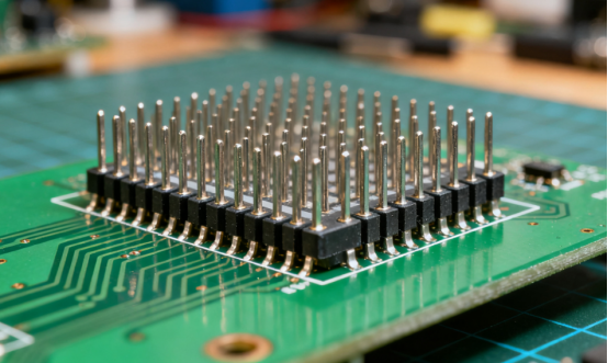
Through-hole Pins vs. Surface-Mount Pins
PCB pins come in various forms, with the two most common types being through-hole and surface-mount pins.
Through-hole pins are inserted through holes in the PCB and soldered on the opposite side. These pins offer strong mechanical support and are ideal for high-durability applications. They are commonly used in older electronics and devices that require robust connections.
Surface-mount pins sit directly on the surface of the PCB and are soldered to pads without passing through the board. These are more compact and suited for modern, high-density electronics where space-saving is a priority. Surface-mount technology (SMT) allows for smaller, thinner devices.
Male vs. Female Pins
Another important distinction is between male and female pins:
Male pins are the protruding connectors, typically used to connect with female connectors. They are commonly found on pin headers.
Female pins are the receiving ends, designed to fit into male pins. These are often found in pin sockets and serve to make temporary or secure connections between components.
Pin Headers, Pin Sockets, and Connectors
Pin headers are rows of male pins that are used to make connections with female pin sockets or directly with other devices. These headers are often found in both through-hole and surface-mount varieties.
Pin sockets are female connectors that accept male pins. They are commonly used in applications where a removable connection is needed, such as with microprocessors and memory chips.
Connectors include various types of male and female pins designed to join circuit boards with external components, such as cables and sensors. They provide flexible, often modular, connectivity solutions.
Applications of Different Pin Types
Through-hole Pins: Durability and Heavy-Duty Applications
Through-hole pins are perfect for applications requiring high mechanical strength and durability. They are commonly used in:
Industrial equipment: High vibrations and heavy loads require robust pin connections that through-hole pins provide.
Automotive electronics: Components such as power systems and sensors that are subject to environmental extremes benefit from the stability of through-hole pins.
Power supplies: Devices that handle significant current flow use through-hole pins for their strong, long-lasting connections.
Surface-mount Pins: Space-Saving and Modern Electronics
Surface-mount pins are ideal for small, high-density circuits. They are used in:
Smartphones: The compact, lightweight design of surface-mount pins helps accommodate the small space in modern electronics.
Wearable devices: In fitness trackers and smartwatches, where space is at a premium, surface-mount pins allow for efficient use of the available board area.
Consumer electronics: For products like laptops, tablets, and TVs, surface-mount pins ensure both functionality and a sleek, thin design.
Connectors: Versatility in Modular Designs
Connectors offer flexibility by allowing removable connections. They are used in a variety of scenarios:
Modular devices: In systems that require frequent updates or maintenance (e.g., desktop computers, gaming consoles), connectors allow components to be easily swapped out.
External device integration: Connectors are commonly used to link a PCB with external devices, like USB ports or HDMI connections, allowing for flexible communication between systems.
Testing and prototyping: In development stages, connectors enable easy testing by allowing quick changes or connections between different circuits.
Examples: Use in Microcontrollers, Sensors, and Power Supplies
Microcontrollers: Pin headers and pin sockets are often used to connect microcontrollers to the PCB. These pins allow for programming and communication with other parts of the system.
Sensors: Surface-mount pins are commonly used in sensors that require compact, low-profile designs for accurate environmental sensing in devices such as thermostats, wearables, and industrial machinery.
Power Supplies: In power supply circuits, through-hole pins are often used due to their ability to carry higher currents and withstand thermal stress.
How to Choose the Right Pin for Your Design
Factors to Consider: Pin Size, Pitch, and Material
Choosing the right pin involves considering a few key aspects:
Pin size: The size of the pin should match the requirements of the components being connected. For instance, larger pins may be necessary for high-power applications, while smaller pins are used in space-constrained designs.
Pitch: The pitch refers to the distance between the centers of adjacent pins. A smaller pitch (e.g., 0.5mm) allows for more pins in a small area, while a larger pitch (e.g., 2.54mm) is used for higher-current applications where more space is needed.
Material: The material of the pin affects conductivity, resistance to corrosion, and overall durability. Common materials include brass for good conductivity, stainless steel for strength, and gold plating for high-performance and low-resistance applications, especially in electronics subject to wear.
Common Mistakes to Avoid When Selecting Pins
Ignoring current requirements: Choosing a pin that cannot handle the required current can lead to overheating and failure. Always consider the current rating for your application.
Overlooking environmental factors: For applications in harsh environments (e.g., high humidity, exposure to chemicals), ensure the material of the pin is resistant to corrosion or choose a pin with appropriate coatings.
Improper pitch selection: Choosing the wrong pitch can lead to poor component placement, misalignment, or insufficient space for soldering.
Case Study: Selecting the Right Pin for a Wearable Electronics Project
When designing a wearable fitness tracker, the design team needed to choose surface-mount pins for the PCB. The pins had to be small enough to fit into a compact device, but strong enough to ensure durability over time. After considering material durability, current requirements, and the need for a thin profile, they selected gold-plated surface-mount pins with a 0.5mm pitch. This ensured a stable connection with low resistance, making the device both reliable and efficient in its power consumption.
By carefully considering the size, pitch, and material of the pins, the team ensured that the wearable device would perform optimally, without taking up too much space or experiencing signal loss.
Materials and Manufacturing of PCB Pins
Materials Used for PCB Pins
Common Materials: Brass, Copper, Gold-Plated Pins
PCB pins are made from several materials, each with its own advantages depending on the application:
Brass: Brass is one of the most commonly used materials for PCB pins. It is an alloy of copper and zinc, offering a good balance between conductivity, strength, and cost. Brass pins are durable and resistant to corrosion, making them ideal for general applications.
Copper: Copper is an excellent conductor of electricity, which makes it a popular choice for PCB pins in high-performance applications. It is often used in situations where high electrical conductivity is critical, such as in power supply circuits. However, copper is prone to corrosion, so it is often coated with another material, like gold, to enhance its durability.
Gold-Plated Pins: Gold-plated pins are typically used in high-end, high-frequency, or precision electronic devices. The gold coating provides excellent corrosion resistance and low contact resistance, which is especially important in high-performance and high-reliability applications. Gold-plated pins are also commonly used in connectors that will undergo frequent mating and unmating cycles, such as in computer motherboards and telecommunications equipment.
Conductivity and Corrosion Resistance Considerations
When choosing the material for PCB pins, two primary factors need to be considered: conductivity and corrosion resistance.
Conductivity: Copper and gold are highly conductive materials, which is crucial in applications like high-speed communication or power delivery. Brass, while good, is not as conductive as copper, but its durability makes it a cost-effective choice in less demanding environments.
Corrosion Resistance: In environments with high humidity or potential exposure to chemicals, materials like gold and gold-plated pins are preferred due to their superior corrosion resistance. Copper, on the other hand, may require additional protection, such as a tin or nickel coating, to prevent oxidation and degradation over time.
Manufacturing Processes
Techniques: Stamping, Molding, and Precision Machining
PCB pins are manufactured using various techniques, each chosen based on the material, required precision, and volume of production:
Stamping: In this process, sheets of metal are fed into a stamping machine, which cuts or forms the material into the desired pin shape. Stamping is a cost-effective method for producing large volumes of pins, particularly for simple designs. It is commonly used for brass pins and is well-suited for mass production of connectors and headers.
Molding: Molding is often used for producing plastic-coated pins or for embedding pins into plastic housings. The metal pin is placed in a mold, and molten plastic is injected around it to create the finished component. This technique is used when pins need to be insulated or when integrating pins into modular connectors.
Precision Machining: For high-precision applications, precision machining involves using computer-controlled machines (CNC machines) to shape and refine the pins to tight tolerances. This method is ideal for producing small quantities of pins with very specific requirements, such as gold-plated pins used in high-frequency circuits.
How Pin Quality is Affected by Manufacturing Methods
The quality of PCB pins is directly influenced by the manufacturing method used. For instance:
Stamped pins are typically high in volume and low in cost, but the process may leave slight variations in pin size or shape, which could affect their performance in very precise applications like high-speed or high-frequency circuits.
Molded pins are highly customizable but may have slightly lower strength due to the inclusion of plastic materials around the pin, which can limit their application to lower-stress environments.
Precision-machined pins offer the highest level of accuracy and uniformity, ensuring consistent electrical performance and mechanical stability. However, this process is more expensive and time-consuming, making it ideal for specialized applications like aerospace, medical devices, or telecom equipment.
Example: Comparison of Stamped vs. Molded Pins in High-Frequency Circuits
In high-frequency applications like 5G communication systems or high-speed data transmission, pin quality becomes especially critical. Stamped pins may suffer from slight deformations that cause signal degradation, such as increased contact resistance or interference due to imperfect electrical connections. On the other hand, molded pins, especially those encased in plastic, might not provide the required precision for high-speed signal integrity. Precision-machined pins, while more expensive, are typically the best choice for these applications because they offer both high accuracy and the best electrical performance, ensuring that the circuit remains stable at high frequencies.
By selecting the right manufacturing process for the required performance, engineers can ensure that the pins perform reliably, contributing to the overall success of the device.
Pin Performance in High-Speed and High-Power Applications
Challenges in High-Speed Circuits
Signal Integrity Issues and the Role of Pin Design
In high-speed circuits, signal integrity is critical. As the speed of signals increases, even the smallest disruptions can lead to performance degradation. PCB pins play a vital role in maintaining signal integrity by ensuring stable connections between components. Poorly designed pins can cause issues like noise, interference, or signal distortion, leading to unreliable circuit operation.
The design of PCB pins influences how effectively they transmit high-frequency signals. For example, sharp corners on pin connectors or improper pin alignment can introduce parasitic inductance and capacitance, which interfere with the signal flow, resulting in signal degradation. To address this, manufacturers often use smooth, rounded pins that minimize these parasitic effects.
How PCB Pins Influence Signal Reflection, Loss, and Transmission Speed
The design of PCB pins directly impacts signal reflection, loss, and transmission speed:
Signal reflection: When the impedance of the pin does not match the impedance of the PCB trace, some of the signal is reflected back, causing errors. Well-designed PCB pins with matched impedance minimize reflection and ensure smoother signal transmission.
Signal loss: High-frequency signals are prone to loss as they travel along the PCB. Gold-plated pins, for instance, help reduce signal loss due to their excellent conductivity and low contact resistance, allowing faster data transfer and higher transmission speeds.
Transmission speed: The speed at which signals travel through a circuit is influenced by the quality of the pin connections. High-speed signals demand low-resistance, high-quality connections to prevent delay and ensure real-time communication between components.
High-Power Applications
Handling Heat Dissipation and Current Requirements
In high-power applications, the demand on PCB pins increases significantly. As current flows through the pins, heat is generated. If pins are not designed to handle this heat, the circuit can overheat, leading to potential damage or failure.
Pin size and material play a key role in heat dissipation. For example, thicker pins or those made of materials with better thermal conductivity, such as copper, can handle higher currents without excessive heating.
Heat sinks or other cooling methods are sometimes used alongside high-power pins to dissipate heat effectively and maintain the integrity of the circuit.
The Need for Thicker Pins or Specialized Connectors in Power Electronics
In power electronics, especially in applications like automotive electronics or industrial machinery, thicker pins or specialized connectors are often necessary. Power circuits require pins capable of carrying high current loads, which standard-sized pins might not be able to handle efficiently. Thicker pins have lower resistance and can distribute heat more effectively, reducing the risk of overheating.
Specialized connectors, such as high-current connectors or hybrid connectors, are designed specifically for power applications. These connectors often include features like dual contacts to distribute the load evenly, ensuring a reliable connection even under high-power conditions.
Example: Using Power Pins in Automotive or Industrial PCBs
In automotive electronics, such as those found in electric vehicle (EV) systems, power pins are essential for linking high-current components like batteries and motors to the rest of the circuit. These pins must be able to handle the intense power requirements without degradation over time. Similarly, industrial PCBs used in machinery or heavy equipment often incorporate thicker, gold-plated pins to ensure reliable connections in high-power environments, reducing the risk of failures during operation.
Designing for Optimal Pin Performance
Best Practices for Pin Placement, Layout, and Routing
To ensure optimal pin performance in both high-speed and high-power applications, engineers must follow best practices in pin placement, layout, and routing:
Pin placement: Place pins as close to the required components as possible to minimize signal travel distance and reduce potential for interference.
Pin layout: Ensure that pins are aligned in such a way that they support controlled impedance and reduce parasitic effects. For high-speed circuits, consider differential pairs for signal transmission.
Pin routing: Use shorter, direct routing for critical signals, and avoid routing high-speed signals through power planes to minimize noise. In high-power applications, consider the current path to reduce resistance and heat generation.
How to Ensure Pin Reliability in Demanding Environments
Pin reliability is crucial in demanding environments where factors like heat, vibration, and corrosion can affect performance. To ensure reliability:
Choose high-quality materials: Use gold-plated pins or tinned copper pins for better corrosion resistance and long-term durability in harsh environments.
Protective coatings: Apply protective coatings to pins, such as conformal coatings, to guard against moisture, dust, or chemicals that could compromise performance.
Rigorous testing: Conduct thermal cycling and vibration tests to evaluate how well the pins perform under stress. This ensures that the pins can withstand extreme conditions without failure.
By following these design practices, engineers can ensure that their PCB pins perform reliably even in high-speed and high-power applications, supporting the overall stability and longevity of the electronic system.
Reliability and Testing of PCB Pins
Factors That Affect Pin Reliability
Physical Wear and Tear, Corrosion, and Fatigue
The reliability of PCB pins is significantly influenced by physical wear and tear, corrosion, and fatigue. Over time, the mechanical stress from repeated connection and disconnection, especially in connectors, can cause pins to loosen or bend, leading to unreliable electrical connections. Corrosion is another common issue, especially when pins are exposed to humidity or harsh chemicals. This degrades the contact surface, increasing resistance and reducing the efficiency of the electrical connection.
Fatigue occurs when pins are subjected to repeated mechanical stress or thermal cycles, causing them to weaken over time. These factors can eventually lead to pin failure, resulting in signal loss, power interruptions, or complete device failure.
Environmental Factors: Moisture, Temperature Extremes, and Vibration
Environmental conditions, such as moisture, temperature extremes, and vibration, can have a profound impact on pin reliability:
Moisture: Exposure to moisture can cause oxidation and corrosion, particularly in copper pins. In environments with high humidity, gold-plated pins or tin-coated pins are often used to resist corrosion.
Temperature Extremes: Both high and low temperatures can cause thermal expansion and contraction, which puts stress on the pins and their solder joints. Pins made of materials like brass or copper are more susceptible to expansion, while gold-plated pins offer better resistance to thermal changes.
Vibration: Devices subjected to constant movement or vibration, such as in automotive or industrial settings, may experience fatigue failure of pins if they are not designed to withstand such forces. Through-hole pins tend to be more durable than surface-mount pins in these cases due to their mechanical strength.
Impact of Poor-Quality Pins on Overall PCB Performance
Using low-quality pins can have significant repercussions on PCB performance. Poor-quality pins may increase electrical resistance, causing signal degradation or power loss. In high-speed or high-power applications, this can lead to unreliable performance, overheating, or system failures. Additionally, low-quality pins may not stand up to environmental stressors like moisture or heat, leading to early failures and a decrease in the overall lifespan of the PCB. In critical systems, such as medical or aerospace applications, this can be particularly damaging.
Testing Methods for PCB Pins
Mechanical and Electrical Testing Procedures
To ensure that PCB pins maintain their reliability, mechanical and electrical testing procedures are vital:
Mechanical testing involves assessing the physical durability of the pins. This can include force testing to ensure the pins can withstand the mechanical stresses of repeated connections or vibrations. Testing for fatigue resistance ensures that the pins can handle long-term usage without failure.
Electrical testing checks the electrical performance of the pins. This includes measuring contact resistance to ensure that the pin provides a stable electrical connection, as well as testing for signal integrity in high-speed circuits to confirm that the pins do not degrade performance.
Continuity Testing and Visual Inspection
Continuity testing checks whether the pin correctly conducts electrical signals and power. It ensures that there is no open circuit due to broken or poorly connected pins.
Visual inspection allows for the detection of physical damage such as bent pins, poor solder joints, or signs of corrosion. Modern inspection systems often use automated optical inspection (AOI) to check for defects and ensure the quality of PCB pins.
Example: Real-World Case of a Failed PCB Pin and Its Implications on Product Reliability
In a real-world scenario, a smartphone manufacturer faced significant reliability issues due to faulty surface-mount pins in the display circuitry. The pins were poorly manufactured, resulting in weak connections that led to intermittent signal loss, causing the display to flicker or go blank. As a result, the manufacturer had to recall a batch of devices and replace the faulty pins, which was costly both in terms of repairs and brand reputation. This highlights the importance of thorough testing and the potential consequences of poor-quality pins on product reliability.
Improving Pin Longevity and Reliability
Surface Finishes, Coatings, and Protective Measures
To enhance the longevity and reliability of PCB pins, various surface finishes, coatings, and protective measures can be applied:
Gold plating improves corrosion resistance and reduces contact resistance, making it ideal for high-performance applications, especially in high-speed circuits.
Nickel plating provides good resistance to corrosion and is often used in industrial or automotive applications where environmental resistance is key.
Tin coating is another option that provides moderate corrosion resistance but is often used in low-cost applications.
For added protection, conformal coatings can be applied to the PCB to shield pins from moisture, dust, or other contaminants.
Maintenance Best Practices
Maintaining pin reliability over time requires routine inspection and cleaning:
Periodic inspection of pins ensures that no corrosion, oxidation, or wear has compromised the pin's ability to function.
Cleaning with appropriate solvents or ultrasonic cleaning ensures that dirt, grease, or flux residues do not affect the connection quality.
Tips for Improving Pin Durability in Extreme Conditions
For applications in extreme environments—such as high-temperature settings or vibration-prone areas—consider the following tips:
Use thicker pins for high-power applications to better dissipate heat and handle higher current loads.
Select higher-quality materials, such as gold-plated or tinned copper pins, to improve both conductivity and corrosion resistance.
Minimize mechanical stress by ensuring that the pins are well-aligned and soldered properly to prevent undue force on the connections.
By following these best practices, engineers can significantly improve the durability and reliability of PCB pins, extending the life of the device and reducing the chances of failure over time.
Trends and Innovations in PCB Pin Technology
Emerging Pin Technologies
Development of Ultra-Miniaturized Pins for Compact Devices
As consumer electronics become smaller and more powerful, the need for ultra-miniaturized PCB pins is growing. These tiny connectors are designed to fit into compact devices such as smartphones, wearables, and medical devices. Advances in microelectromechanical systems (MEMS) and 3D printing have enabled the creation of ultra-small pins that maintain high performance despite their size.
Miniaturization allows for dense circuit layouts without sacrificing functionality. In devices like smartwatches or hearing aids, miniaturized pins help reduce the overall size of the product, making it more comfortable and portable.
Example: In modern smartphones, connectors with micro-pitch (0.5mm or smaller) are used to connect sensors and antennas while occupying less board space, supporting both performance and portability.
Advances in Smart Connectors and Pins with Integrated Features (e.g., Sensors)
Innovative smart connectors are emerging that integrate additional features directly into the pin design. These intelligent connectors include built-in components like sensors, temperature monitors, or current detectors, allowing for smarter communication between parts of the circuit.
Sensors integrated into pins can provide real-time data about the health of the device, such as monitoring temperature fluctuations or signal integrity during operation. This feature is especially valuable in high-performance and critical applications like automotive electronics and medical devices.
Example: In smart home systems, pins with integrated sensors can monitor voltage fluctuations in power circuits, alerting the system to potential failures before they cause damage.
Trends Toward Flexible and Stretchable PCBs for Wearable Tech
The rise of wearable technology is driving innovations in flexible and stretchable PCBs. These PCBs, which can bend, stretch, and conform to the body, require specialized flexible pins that maintain reliable connections despite changes in shape and size. This is particularly important for fitness trackers, smartwatches, and health monitoring devices.
Flexible pins must maintain both mechanical integrity and electrical reliability while enduring constant motion. These developments are pushing the boundaries of what is possible with traditional rigid PCBs.
Example: Wearable ECG monitors use stretchable PCB pins to maintain a stable connection while conforming to the body’s movements, ensuring accurate health monitoring.
The Future of PCB Pins in Consumer Electronics
Influence of Internet of Things (IoT) on Pin Requirements
The Internet of Things (IoT) is driving a shift toward smaller, smarter, and more efficient devices, which in turn influences the design of PCB pins. As IoT devices become more interconnected, the demand for high-density connectors that can handle multiple functions simultaneously grows.
IoT devices, such as smart thermostats or wearables, often require pins that can accommodate multiple signal types (e.g., power, data, and communication) in a compact space. This has led to the development of multi-functional pins that combine different signal paths, reducing the need for separate connectors.
Example: A smart thermostat uses multi-functional PCB pins to transmit both power and data to various sensors, ensuring seamless communication and energy efficiency.
Anticipated Improvements in Pin Materials and Performance
The future of PCB pins lies in continued innovation in materials and performance. Advancements in materials science are likely to lead to pins with superior conductivity, strength, and durability.
New materials, such as graphene, carbon nanotubes, or advanced alloys, are being researched for their potential to enhance pin performance. These materials promise lower resistance, greater heat resistance, and increased flexibility, which will be crucial for high-speed and high-power applications.
Example: In 5G devices, the demand for low-resistance, high-frequency pins will drive the use of graphene-based materials to support fast data transmission without signal loss.
Additionally, improvements in surface treatments and coatings, such as nano-coatings for corrosion resistance or anti-microbial coatings for healthcare applications, are expected to enhance the longevity and reliability of PCB pins in even more challenging environments.
In summary, the future of PCB pins in consumer electronics is marked by miniaturization, integration of smart features, and advances in materials, ensuring that these connectors evolve to meet the growing demands of increasingly sophisticated and compact electronic devices.
Conclusion
PCB pins are essential for ensuring reliable connections in electronic circuits, facilitating power and signal transmission. The choice of pin type, material, and design directly impacts the performance and longevity of a device. Whether for high-speed communication or high-power applications, selecting the right pin and ensuring its proper placement and testing are crucial steps. As technology evolves, so does the role of PCB pins, with innovations like miniaturization, smart connectors, and flexible designs paving the way for the next generation of wearable devices, IoT, and high-performance electronics. For expert advice and solutions, feel free to reach out to PCBMASTER, a trusted PCB supplier.
FAQs
What is the difference between through-hole and surface-mount PCB pins?
Through-hole pins are inserted into holes that pass through the PCB and are soldered on the opposite side. This makes them ideal for applications requiring high mechanical strength and durability, such as in industrial and automotive electronics. On the other hand, surface-mount pins sit directly on the PCB surface and are soldered onto pads. They are generally used in smaller, modern electronics where space-saving is crucial, such as smartphones and consumer devices. Through-hole pins are more robust, while surface-mount pins offer a more compact and efficient design.
How can I prevent PCB pins from corroding over time?
To prevent corrosion, consider using pins made from corrosion-resistant materials such as gold-plated pins or tin-coated pins. Nickel and silver coatings also offer good protection against environmental factors like moisture and chemicals. Additionally, conformal coatings applied to the entire PCB can protect pins from exposure to humidity and other corrosive elements. Proper storage and handling during assembly and use, as well as avoiding excessive exposure to extreme conditions, can also help prolong the life of your PCB pins.
What is the role of PCB pins in signal integrity?
PCB pins play a critical role in signal integrity by ensuring stable and reliable electrical connections between components. Poorly designed or low-quality pins can introduce resistance, noise, and signal reflections, which degrade the overall performance of high-speed circuits. High-quality pins, especially those with low contact resistance (e.g., gold-plated pins), help maintain the integrity of signals, allowing for faster data transmission and reducing the risk of errors in communication between components.
How do I choose the right pin material for high-power applications?
For high-power applications, select pins made from materials with excellent conductivity and thermal resistance, such as copper or brass. These materials are effective at carrying higher current loads without overheating. In some cases, gold plating can be added to ensure corrosion resistance and low resistance at the contact points. For heavy-duty applications where high temperatures are expected, thicker pins or specialized connectors may be required to effectively manage heat dissipation and maintain electrical reliability.
What are the most common causes of pin failure in PCBs?
Pin failure in PCBs can be caused by several factors, including mechanical stress, corrosion, and fatigue. Over time, pins can loosen or break due to repeated connections and disconnections or excessive vibration, particularly in high-stress environments. Corrosion from moisture or chemicals can weaken the pins' conductivity, while thermal cycling can cause pins to expand and contract, leading to fatigue. Additionally, poor soldering or low-quality materials can result in poor electrical connections, leading to pin failure. Regular inspection and testing can help detect early signs of failure and prevent issues before they affect device performance.

