


Essential Insulation for Plug in Component Best Practices and Tips
Introduction
In PCB assembly, through-hole components (such as DIP-packaged chips, resistors, capacitors, connectors, etc.) are familiar to many engineers. They are soldered into plated through-holes on the PCB, offering simplicity, robustness, and low cost, and are still widely used in industrial equipment, home appliances, power supplies, and more. However, one detail is often overlooked: Insulation for through-hole components.
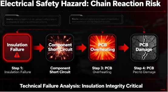
To ensure optimal performance and safety, it is important to understand the differences between insulation methods for through-hole components. Don’t underestimate this layer of “insulation protection.” In high-voltage, humid, dusty, or other demanding scenarios, it directly determines the PCB’s lifespan and safety. For example, an inadequately insulated through-hole capacitor on an industrial power supply PCB might lead to leakage current between pins, causing a short circuit and burning out the entire board. Similarly, insulation failure in a connector on an appliance PCB can pose an electric shock risk. This article deconstructs the core aspects of insulating through-hole components: why it’s essential, what solutions to use in different scenarios, and how to solve common problems, helping you avoid PCB failures caused by improper insulation.
Part 1: Understanding the ‘Why’ – The 3 Core Risks Mitigated by Insulation
Many assume that “since through-hole component pins are soldered to the PCB and protected by solder mask, extra insulation is unnecessary.” This thinking fails to account for the complex risks in real-world applications. Insulating through-hole components is fundamentally about mitigating three core issues:
Preventing Leakage Current Between Pins
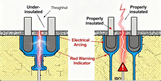
Avoiding shorts between adjacent pins. The pins of through-hole components are often closely spaced (e.g., some DIP IC pins have a pitch of only 2.54mm). In high-voltage environments (like a 220V input section on a power supply PCB), insufficient creepage distance between pins can lead to leakage current. Creepage distance is the path along the insulation surface between two conductive parts. If this distance is less than the safety standard (e.g., ≥6mm for high-voltage scenarios), a leakage path can form even without direct contact, leading to short circuits.
Example: On an industrial power supply PCB, the pins of a through-hole bridge rectifier were 3mm apart with no extra insulation. In a humid environment, moisture condensed on the pins, creating a leakage path that caused a short circuit upon power-up, destroying the board. Proper insulation (e.g., adding an insulating spacer between pins) blocks such leakage paths.
Preventing Contact with External Conductors
Avoiding accidental shock or shorts. Many PCBs are mounted near metal enclosures or other wiring inside devices. Excessively long pins of through-hole components might accidentally contact the metal casing (e.g., a connector pin touching the chassis), potentially energizing the casing and creating a shock hazard, or contacting adjacent wires, causing shorts between different circuits.
Example: In a washing machine control PCB, the pins of a through-hole water level sensor protruded 5mm from the board. During operation, vibration caused a pin to contact the metal inner drum, energizing it. The ground fault circuit interrupter thankfully tripped, preventing a serious accident. Insulating sleeves on the pins would have prevented this contact.
Mitigating Environmental Degradation
Extending component lifespan. In harsh environments—humid, dusty, oily (e.g., industrial workshops, kitchen appliances)—the pins of through-hole components are susceptible to corrosion. Moisture, dust, and contaminants can accelerate oxidation, leading to rust and poor contact, while grease can degrade insulation, promoting leakage.
Example: On a range hood control PCB, the pins of a through-hole relay, exposed to cooking oil fumes without insulation, corroded within six months, causing relay failure and hood malfunction. Coating the pins with insulating conformal coating isolated them from fumes and moisture, extending service life beyond three years.
Part 2: Choosing the Right Solution – 3 Main Insulation Methods for Through-Hole Components
The number of insulation solutions available depends on the application and component type. Insulation for through-hole components isn’t one-size-fits-all. The method must match the application and component type. Here are three common industry methods, their applications, and key points:
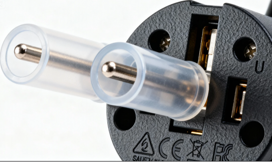
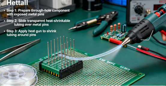
Scenario 1: High Voltage, Close Pin Spacing (e.g., Power Supplies, Industrial Equipment) → Use “Insulating Sleeves / Heat-Shrink Tubing”
Applicable Components: Through-hole capacitors, bridge rectifiers, high-voltage connectors, etc., with thicker pins requiring individual insulation.
Method:
·Select sleeves (PVC or Silicone) matching the pin diameter. For high voltage, prioritize high-voltage rated silicone tubing (rated voltage ≥250V).
·Slide the sleeve over the component pin, covering the section from the component body to the PCB surface (typically 5-10mm long). Cover any excessive pin length protruding from the PCB.
·For heat-shrink tubing, apply heat (120-150°C) with a hot air gun to shrink it snugly onto the pin.
·Advantages: Excellent insulation, high voltage resistance (silicone can withstand >1000V), simple installation.
·Note: Do not cover the solder joint itself, as this can compromise solder reliability.
Example: A power supply manufacturer uses 10mm long silicone insulating sleeves on the pins of filter capacitors on its 220V input PCBs, rated for 500V, effectively eliminating pin leakage issues.
Scenario 2: Humid, Dusty Environments (e.g., Appliances, Outdoor Equipment) → Use “Conformal Coating / Potting Compound”
Applicable Components: Rows of components (DIP ICs, connectors) or entire through-hole areas requiring bulk insulation.
Method:
·Select a conformal coating suitable for the environment (waterproof for humidity, anti-contamination for dust, RoHS compliant for appliances).
·Apply the coating evenly via brush or spray onto the pins, solder joints, and surrounding PCB area. Control thickness to 0.1-0.2mm (excessive thickness impedes heat dissipation).
·For extreme environments (e.g., outdoor power PCBs), use potting: encapsulate the entire through-hole area with a compound (e.g., epoxy). Potting compounds are often combined from two components, such as resin and hardener, before application. Once cured, it forms a sealed, insulating layer blocking moisture and dust completely.
·Advantages: Comprehensive protection for multiple components simultaneously.
·Note: Select high-temperature resistant coatings/potting (≥120°C) to prevent melting during soldering or operation.
Example: An outdoor LED driver PCB uses waterproof conformal coating on the area containing a through-hole power management IC. Even when exposed to rain, it functions reliably, reducing the failure rate from 15% to 0.5%.
These methods help protect components from environmental hazards and improve reliability. Potting and conformal coating are used to insulate multiple pins or areas at once, providing a robust barrier against moisture and dust.
Scenario 3: Proximity to Metal Enclosures (e.g., Appliances, Instruments) → Use “Insulating Spacers / Barriers”
Applicable Components: Connectors, switches, etc., whose pins might contact the metal enclosure.
Method:
·Select insulating spacers (1-2mm thick, materials like FR-4, plastic; dielectric strength ≥2kV/mm). Cut to size based on component shape.
·Place the spacer between the component and the metal enclosure, or around the pins, ensuring sufficient insulation distance (generally ≥5mm).
·If an entire section of the PCB is close to metal parts, install an insulating barrier (e.g., plastic sheet) between the PCB and the metal.
·Washers can be used in conjunction with spacers to secure insulation barriers in place.
·Advantages: Quickly increases creepage/clearance distance, prevents accidental contact.
·Note: Secure spacers/barriers firmly to prevent displacement from vibration.
Example: A desktop instrument’s control PCB had a through-hole power jack whose pins were close to the metal chassis. Adding an FR-4 insulating spacer eliminated the contact risk, allowing the product to pass safety certification tests.
Part 3: Pitfall Avoidance Guide – 4 Common Insulation Mistakes to Stop Making
Many failures occur despite insulation efforts, often due to these common pitfalls:
Mistake 1: Wrong Insulation Material – Using Low-Voltage Rated Materials in High-Voltage Applications.
·Typical Error: Using PVC sleeving rated for 100V on a 220V PCB, leading to breakdown and insulation failure.
·Correct Approach: Select materials based on the PCB’s working voltage, following the “voltage rating ≥ 2x operating voltage” rule. Use standard PVC for low voltage (≤36V); mandatory use of high-voltage rated silicone or epoxy materials for high voltage (≥220V). Also check the material’s temperature rating (e.g., ≥105°C for appliances, ≥125°C for industrial).
Mistake 2: Incomplete Coverage – Missing ‘Critical Spots’
·Typical Error: Sleeving only the upper part of a capacitor pin, leaving the solder joint exposed where damaged solder mask could cause leakage to adjacent pins.
·Correct Approach: Insulation must cover the entire pin area from the component body to the PCB surface. If solder joints are exposed, coat them additionally with insulating varnish. For component rows (e.g., DIP ICs), ensure insulation fills gaps between all pins. Proper insulation work ensures both safety and performance.
Mistake 3: Impeding Heat Dissipation – Overly Thick Material or Tight Encapsulation.
·Typical Error: Power components (e.g., resistors) over-insulated with multiple layers of heat-shrink or fully potted without thermal pathways, causing overheating and failure.
·Correct Approach: For power components, prioritize thermal management alongside insulation. Use thin materials (e.g., 0.1mm coating), select thermally conductive potting compounds (≥0.8 W/m·K), and leave air gaps around components for heat dissipation, avoiding complete sealing.
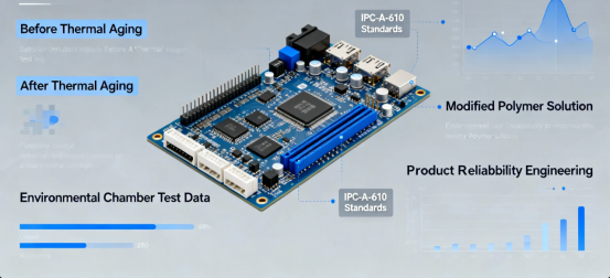
Mistake 4: Ignoring Aging – Using Prone-to-Degrade Materials.
·Typical Error: Using cheap, low-quality materials (e.g., recycled PVC sleeves) that crack and degrade quickly under heat or UV exposure, losing insulating properties within months.
·Correct Approach: Select industry-standard materials with relevant certifications. Prioritize products with RoHS, UL listings – e.g., UL94 V-0 rated sleeves (flame retardant), IEC 60664 compliant coatings (aging resistance) – ensuring they last the PCB’s expected lifespan (typically 3-5 years).
Part 4: Case Studies – From Failure to Solution
Let’s examine two real cases showing the consequences of poor insulation and how correct methods solved them.
Case 1: Industrial Control PCB – Connector Insulation Failure Causing Frequent Tripping
Problem: A factory line control PCB used a through-hole power connector (220V input) without extra insulation. Dust and humidity in the workshop built up on the pins, degrading insulation and causing leakage current, which repeatedly tripped the factory’s ground fault protector, halting production.
Solution:
1.Replaced the connector with one featuring an integral insulating housing (Flame-retardant PA66, Rating: AC 250V).
2.Applied waterproof conformal coating (125°C rating, UL94 V-0) around the connector pins and solder joints.
3.Installed an FR-4 insulating barrier between the PCB and the metal enclosure.
Result: No further leakage trips occurred; equipment ran continuously for 6 months without failure.
Case 2: Appliance PCB – Capacitor Insulation Failure Causing Short Circuit
Problem: On a brand oven’s control PCB, the pins of a through-hole filter capacitor (400V rated) were 3mm apart, lacking insulation. During high-temperature baking, the solder mask between pins degraded and cracked due to heat, leading to leakage, eventual short circuit, and board failure.
Solutin:
1.Fitted high-voltage silicone sleeves (1000V rating, 200°C) on the capacitor pins, covering them from body to PCB.
2.Re-laid out the PCB to increase pin spacing from 3mm to 8mm, meeting creepage requirements.
3.Sprayed high-temperature conformal coating around the capacitor for added protection.
Result: PCB failure rate for that oven model dropped from 8% to 0.3%, significantly reducing customer complaints.
Conclusion: Insulation for Through-Hole Components – The PCB’s ‘Silent Guardian’ for Safety
In PCB design and assembly, insulating through-hole components might not be the most glamorous task, but it’s a critical safety measure. Especially in fields demanding high reliability like industrial, appliances, and power supplies, proper insulation can prevent over 90% of PCB failures caused by pin leakage and shorts.
To recap the key takeaways:
·Match Solution to Scenario: Use sleeves for high voltage, coating for moisture, spacers for near-metal.
·Specify Qualified Materials: Ensure voltage, temperature, and aging resistance meet application demands. Prefer certified products.
·Execute Meticulously: Ensure complete coverage without compromising thermal management.
Don’t neglect this “silent protection.” Implementing proper insulation for your through-hole components is fundamental to creating safer, more durable PCBs.
FAQs
Q. What is the core function of insulation for through-hole components on PCBs?
A. Its primary role is to block leakage current paths between pins and between pins and external conductors, thereby avoiding short-circuit and electric shock risks. It also isolates moisture, dust, and other contaminants to prevent electrochemical migration (such as dendrite growth) and ensure the stability of the PCB's insulation resistance.
Q. What are the common insulation methods?
A. They are categorized into three types: use insulating sleeves / heat-shrink tubing for high-voltage scenarios; use insulating varnish / potting compound for humid/dusty environments; and use insulating spacers / barriers for areas near metal parts. Match the method to the specific scenario as needed.
Q. What key specifications of insulating materials should be focused on during selection?
A. Focus on the withstand voltage rating (must be ≥2x the operating voltage), temperature resistance (compatible with PCB operating temperature), insulation resistance (typically must be ≥10⁹ Ω), and flame retardancy rating (UL94 V-0 is recommended).
Q. What is creepage distance?
A. How is it matched to insulation requirements during design? It refers to the path length of leakage current along the insulation surface. A distance of ≥6mm is required for high-voltage scenarios (≥220V), and ≥0.25mm for low-voltage scenarios. Use insulating materials to compensate when the distance is insufficient.
Q. What are the common causes of insulation failure?
A. Incorrect material selection (e.g., using low-voltage sleeves for high voltage), incomplete coverage (missing solder pads / pin roots), residue contamination leading to electrochemical corrosion, or material aging and cracking.
Q. How can insulation for power-type through-hole components also address heat dissipation?
A. Select thin, highly thermally conductive insulating materials (e.g., potting compound with thermal conductivity ≥0.8 W/(m·K)), avoid complete sealing, reserve gaps for heat dissipation, and prioritize using insulating varnish instead of thick sleeves.
Q. How is insulation done for fine-pitch through-hole components on high-density PCBs?
A. Use low-viscosity insulating varnish for precise application into pin gaps, or use custom insulating spacers for isolation. Simultaneously, control the solder mask accuracy to prevent misalignment that compresses the insulation distance.
Q. How to test whether the insulation treatment is qualified?
A. Routinely measure insulation resistance (must be ≥500 MΩ in damp-heat environments); perform breakdown voltage tests additionally for high-voltage scenarios; long-term reliability can also be verified through SIR (Surface Insulation Resistance) testing.
Q. If leakage current occurs after insulation treatment, what is the most likely problem?
A. It is often due to insufficient material withstand voltage leading to breakdown, coverage omissions on solder pads / pin gaps, or residual ionic contaminants causing surface corrosion. Targeted material replacement or rework/cleaning is required.
Q. Are there special requirements for insulating connector-type components?
A. Prioritize models with insulated housings (e.g., PA66 material). The solder points of the pins require additional coating with insulating varnish. For sealed applications, use low-sulfur rubber sealing rings to enhance protection.
Author: Jack Wang

