


Applications of Stainless Steel Core PCBs Technological Breakthroughs from New Energy Vehicles to Deep-Sea Equipment
I. Technical Characteristics and Market Positioning of Stainless Steel Core PCBs

According to the latest 2024 report by Prismark, the global metal core PCB market has reached $5.8 billion, with stainless steel-based products surging from 7% in 2020 to 19% of the market share. Its core competitiveness lies in:
1. Extreme Environmental Adaptability
①Tensile Strength: 520 MPa (2× higher than aerospace-grade aluminum)
②Corrosion Resistance Lifespan: 15 years (ASTM G85 acid salt spray test)
③Thermal Resistance: 0.8℃·cm²/W (1mm thickness), 33% lower than aluminum substrates
2. Cost-Effectiveness Turning Point
①SUS304 Substrate Price in 2023: Reduced to $85/m² (42% drop since 2018)
②Lifecycle Cost: 28% lower than aluminum substrates (Tsinghua Shenzhen International Graduate School calculation)
II. New Energy Vehicle E-Systems: Solving Thermal Runaway Challenges
2.1 Motor Controller Case Study
A Leading Automotive Manufacturer’s 800V High-Voltage Platform Project:
①Operating Temperature: Sustained 150℃ (traditional solutions max at 120℃)
②Thermal Stress Test Results:
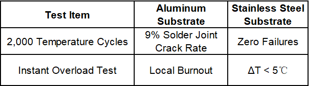
Key Design Innovations:
1. Direct contact between power modules and substrate via window openings (65% reduction in thermal resistance)
2. Nano-silver sintering process (thermal conductivity: 250 W/mK)
3. Substrate thickness optimized to 0.8mm (30% weight reduction)
2.2 Onboard Charger (OBC) Breakthrough
Mass Production Data for a 22kW OBC:
①Power Density: 3.2 kW/L (industry average: 2.5 kW/L)
②Full-Load Temperature Rise: 42℃ → 29℃ (ambient temperature: 25℃)
③EMI Radiation Levels:
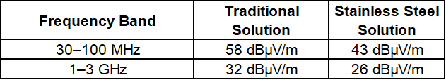
III. Industrial Equipment: Reliability Revolution in Heavy-Duty Scenarios
3.1 Industrial Robot Servo Drivers
An International Brand’s Sixth-Axis Joint Module:
①Vibration Resistance: Passed IEC 60068-2-64 20Grms test
②Protection Rating: IP67 (direct exposure to cutting fluid)
③MTBF: Increased from 30,000 to 80,000 hours
Key Innovations:
Sandwich Structure Design (Figure 1):
①Top Layer: 0.3mm PI copper-clad laminate (signal layer)
②Middle Layer: 1.0mm SUS304 (thermal conduction + structural support)
③Bottom Layer: 0.2mm graphene coating (EMI shielding)
Laser Microvia Technology: Aperture <50μm, positional accuracy ±5μm
3.2 Photovoltaic Inverter Cooling Solutions
Comparison Test at a 5MW Power Plant (Ambient Temperature: 45℃):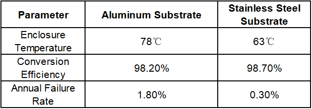
Integrated Fin Design (Figure 2):
40% increase in heat dissipation area with only 15% weight gain
IV. Marine Engineering: Breaking Deep-Sea Corrosion Barriers
4.1 Submarine Cable Repeaters
A Transoceanic Communication Project (Depth: 5,500m):
Pressure Test: Withstood 100 MPa hydrostatic pressure (equivalent to 10,000m depth)
Anti-Corrosion System:
①Base Material: SUS316L (Mo content: 2.5%)
②Coating: PEEK + nano-ceramic composite layer (total thickness: 80μm)
Field Data:
①10-year corrosion rate <0.03mm/year (ASTM G59 standard)
②Maintenance cycle extended from 18 months to 5 years
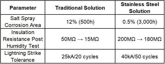
4.2 Offshore Wind Power Converters
Comparison Data for an 8MW Wind Turbine:
V. Military & Aerospace: Extreme Environment Validation
5.1 Satellite Power Controllers
A Low-Earth Orbit Satellite Project:
Thermal Cycling Range: -180℃ to +150℃ (vacuum environment)
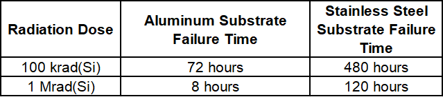
Radiation Resistance:
Laser Direct Structuring (LDS) Technology:
Line precision ±3μm, eliminating side etching issues in traditional processes
5.2 Armored Vehicle Electronic Systems
Field Tests for a Main Battle Tank:
Impact Resistance: Passed MIL-STD-810H 40g/11ms test
Environmental Protection:
①Mold Resistance: Grade 0 (GB/T 2423.16)
②Salt Spray Resistance: >3,000 hours without corrosion
③Dust Protection: IP6K9K rating
VI. Cost Control and Mass Production Practices
6.1 Material Innovation for Cost Reduction
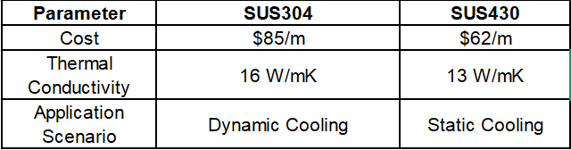
SUS430 vs. SUS304 Comparison:
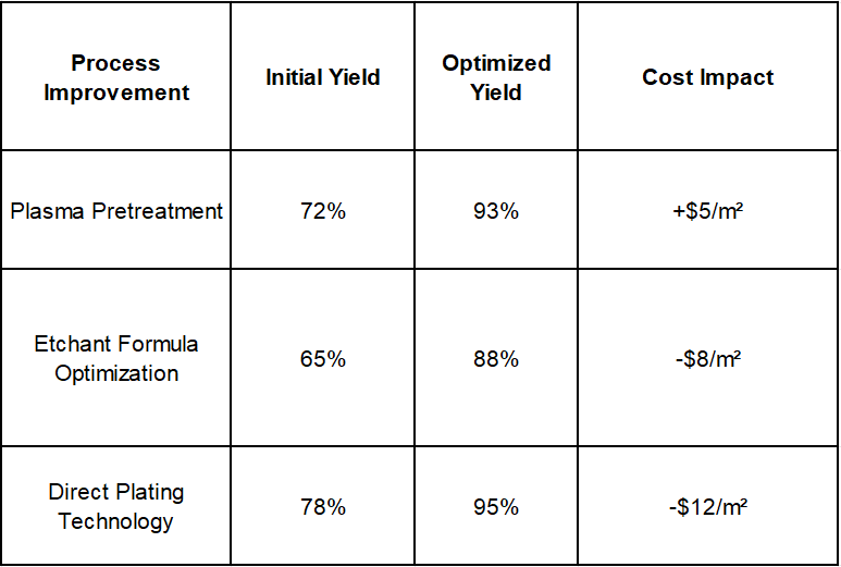
6.2 Process Optimization for Yield Improvement
Production Data from a Leading Manufacturer:
Technological Outlook: Next-Generation Stainless Steel Core PCB Trends
1. Ultra-Thin Technology: 0.3mm-thick substrates validated for automotive standards
2. Smart Thermal Management: Integrated temperature-sensing films (±0.5℃ accuracy)
3. Green Manufacturing: Etchant waste recovery rate increased to 98%
(Data sources: IPC, Fraunhofer Institute, and field reports from industry leaders. Case details are technically desensitized.)
Future Market Prospects of Stainless Steel Core PCBs

