








EV BMS PCB: How to Choose the Right PCB for Electric Vehicle Battery Management Systems
Electric vehicle batteries work with high voltage, big current and constantly changing driving conditions. High quality battery cells are not enough to keep them safe and efficient – you need an effective Battery Management System (BMS) . The BMS constantly monitors the battery voltage, current, and temperature, calculates the battery’s state of charge (SOC) and state of health (SOH) , and protects against problems like overcharging, over-discharging, overheating, and short-circuiting. Even the best battery pack will not be able to provide consistent performance or long life span without a reliable BMS.
At the core of every EV BMS is the printed circuit board (PCB) . The PCB is not only a substrate for mounting electronic components. It is an electrical connection, it carries sensitive measurement signals, it distributes power and helps manage heat across the system. Bad PCB design or selection can lead to signal errors, lower reliability and even risk battery safety. So, selection of the right EV BMS PCB is an important step in the process of developing a reliable battery management system.
This guide is all about choosing the right PCB for your electric car battery management system. You will learn about the special requirements of EV BMS hardware, the importance of PCB characteristics, the common types of PCBs, and the key considerations when choosing the best PCB for different EV BMS applications.
What Is an EV Battery Management System (BMS)?
An EV BMS is an electronic control system that monitors, controls and protects an EV battery pack. It ensures safe, efficient and reliable operation of the battery during its life.
The EV battery pack is made of hundreds of lithium-ion cells working together. Due to their different nature, age and behaviour these cells should be constantly monitored and controlled. The EV BMS can collect data from the battery pack, analyze the condition of the battery pack in real time, and make decisions to optimize charging, discharging, and overall battery performance. A good quality battery pack, without a reliable BMS, will not provide consistent performance and meet automotive safety requirements.
What is the purpose of an EV BMS?
The EV BMS is developed to monitor state of the battery, estimate state of the battery and protect battery pack from unsafe operation conditions.
The Battery Management System (BMS) of an EV does many functions to ensure safe and efficient operation of the battery:
- Monitor battery voltage, current, and temperature to detect abnormal conditions in real time.
- Calculate State of Charge (SOC) to estimate the remaining battery capacity.
- Estimate State of Health (SOH) to evaluate battery aging and overall health.
- Protect the battery pack from overcharging, over-discharging, overcurrent, overheating, and short circuits.
For example, with DC fast charging, if one battery cell reaches its temperature limit before the others, the BMS can reduce the charge current or stop charging altogether. This helps improve safety, prevent battery damage and extend battery life.
What makes an EV BMS different from other BMSs?
An EV BMS has been designed for higher voltage, more cells, higher measurement accuracy and tighter safety requirements compared to battery management systems in most other applications.
Electric vehicle BMSs need to face much more serious operating conditions than BMSs for consumer electronics or small energy storage systems. The main features are
- High-voltage battery packs, usually between 400 V and 800 V or more.
- Large numbers of battery cells that need each cell to be continuously monitored.
- High measurement accuracy for optimal battery balancing and charging control.
- Long service life and functional safety for reliable operation under vibration, temperature changes and years of daily driving.
For example, a battery pack for a power tool may have fewer than 20 cells, whereas a battery pack for an EV may have several hundred. To manage such a large and complex battery system you need far more sophisticated hardware and software.
What are the main hardware components of an EV BMS?
The main hardware components of an EV BMS are battery monitoring ICs , microcontroller , communication interfaces , current sensing , and protection circuits .
Each plays a part in the safe and reliable operation of the battery:
- Battery monitoring ICs are used to measure voltage and temperature accuracy for each cell.
- The microcontroller (MCU) processes the measurement data to calculate the SOC and SOH and to control the charging, discharging and protection strategies.
- Communication interfaces like CAN bus, LIN bus etc. allow exchange of information with the vehicle control unit, charger and other electronics.
- Current sense and protection circuitry. The current sensing circuits sense the current flowing through the battery and sense the faults like over current, short circuit.
They are implemented on the EV BMS PCB which is the base of the whole hardware system. The harsh environment of electric cars requires a proper PCB design for reliable signal propagation, stable power distribution and reliable operation.
Why Is PCB Selection Important for an EV BMS?
The choice of PCB is an important process as it is directly related to the accuracy, safety, reliability and long-term performance of an EV Battery Management System (BMS).
An EV BMS PCB is so much more than a base for electronic parts. It carries the sensitive measurement signals, distributes power, dissipates heat and interconnects every part of the battery management system. The wrong choice of PCB material, layer structure or layout can decrease the accuracy of measurements, increase electrical interference and reduce the lifetime of the system. The choice of the correct PCB is vital for the correct performance of BMS in the harsh conditions of electric vehicles.
How does the PCB affect battery monitoring accuracy?
A good PCB design improves the precision of battery monitoring by providing stable signal propagation, reduced electrical noise and support for proper analogue measurements.
Battery monitoring circuits measure small changes in voltage, current and temperature. These readings will be affected by any small electrical interference. How an EV BMS PCB Improves Measurement Accuracy
- Signal transmission from the sensors to the monitoring ICs is guaranteed to be stable .
- Proper grounding and routing of signals to minimize electrical noise.
- Accurate sensing of voltage and current with reliable analogue measurements
For example, a few millivolts of cell voltage difference can impact battery balancing decisions. If PCB is noisy the measurement can be distorted and BMS can misinterpret the state of the battery. Good PCB design will reduce the interference of signals and help BMS make correct control decisions.
Why is PCB reliability critical in EV applications?
The safety of the EV BMS under high voltages, high temperatures, vibration and other harsh automotive conditions makes the reliability of the PCB a key issue.
Unlike consumer electronics, an EV Battery Management System PCB is exposed to harsh environments throughout the life of the vehicle. For reliable operation the PCB must provide:
- High voltage insulation to safely disconnect power circuits and prevent electrical leakage.
- Resistance to repeated cycles of heating and cooling during charging and driving. Thermal stability.
- High resistance and vibration resistant, for severe environments such as unpaved roads, humidity, dust and temperature changes.
For example, an electric vehicle could be exposed to freezing temperatures in the winter and high battery temperatures during fast charging in the summer. The automotive PCB is reliable and can maintain stable electrical performance under the two conditions, which can decrease the risk of unexpected failures.
How does PCB design improve overall BMS performance?
Good PCB design contributes to the performance of the BMS by reducing electromagnetic interference, better heat dissipation, and higher long-term reliability of the system.
Apart from selection of the right PCB material, PCB layout has a major role in the overall system performance. Effective EV BMS PCB design can help:
- Enhance electromagnetic compatibility (EMC) by optimizing grounding and signal routing to reduce interference between electronic circuits.
- Correct copper distribution, thermal vias and component placement avoiding excessive temperatures improving heat dissipation.
- Iimprove long term reliability by reducing the electrical stress and ensuring stable operation for years of vehicle operation.
A practical example is placement of high power components. Accurate readings and longer life of the entire Battery Management System can be achieved by implementing thermal management features and moving heat-generating devices away from sensitive measurement circuits.
What Type of PCB Is Best for an EV Battery Management System?
What is the best PCB for EV Battery Management System ( BMS ) ? The best PCB for EV BMS depends on the voltage and current , size and reliability requirements of the system . Most EV BMS designs are based on multilayer PCBs made of automotive-grade FR-4, while specific applications are using technologies such as HDI, heavy copper, or rigid-flex PCBs.
The engineers do not use one type of PCB but select the right combination of PCB structure, material, copper thickness and surface finish in order to meet the performance and safety requirements of the battery management system.
Why are multilayer PCBs the preferred choice?
Multilayer PCBs are preferred because it allows higher routing density, better signal organization and better Electromagnetic compatibility (EMC) .
Typically an EV BMS consists of battery monitoring ICs, microcontrollers, communication interfaces and protection circuits on one PCB. The use of a multilayer PCB makes the integration of these circuits easier because it permits:
- More routing density for complex electronic designs.
- Separate signal and power layers to reduce interference between sensitive analogue signals and high current traces.
- Improved electromagnetic compatibility (EMC) performance to allow reliable operation of the BMS in the electrically noisy environment of automotive applications.
For example in a normal 6 layer pcb you can have a power layer, a ground layer and the rest for route signals. This layout is easier to design than a two layer PCB and has better signal integrity.
Which PCB materials are commonly used?
Automotive grade FR-4 is the most common PCB material used for EV BMS applications, but when higher thermal or electrical performance is required, high-Tg and specialty laminates are deployed.
Material selection influences reliability and cost of manufacture. Some of the common ones are:
- Automotive Grade FR-4: The most preferred material that provides good electrical insulation, mechanical strength and cost effectiveness to most of the EV BMS designs.
- High Tg FR-4: Improved thermal stability to better suit applications with frequent temperature cycling.
- Specialty laminates: For use when the BMS needs better thermal performance, lower dielectric loss or better performance at high frequency.
In terms of performance, reliability and manufacturing cost, most electric vehicle battery management systems operate best with automotive-grade FR-4.
When should heavy copper PCBs be used?
Heavy copper PCBs are used in the EV BMS for high current paths or power distribution circuits where higher current carrying capability is required.
Most of the monitoring circuits are only carrying a very small current but some parts of the BMS carry much higher electrical loads. Heavy copper PCBs have several benefits in these areas:
- Higher current-carrying capacity without excessive temperature rise.
- Lower electrical resistance, reducing power loss.
- Improved heat dissipation for power distribution circuits.
This is useful for power distribution networks , battery disconnect circuits or high current sensing paths where thicker copper can be designed for more reliability and less overheating .
When is an HDI PCB a better option?
If the EV BMS requires high density of circuits, small size or fine pitch electronic components, HDI PCB will be a better choice.
Then there are HDI ( High Density Interconnect ) PCBs which use microvias and finer traces to fit more circuits into a smaller space . They are typically selected to:
- Space-saving small BMS modules for mounting
- Dense Routing of Fine Pitch Automotive ICs
- More integrated design for better use of PCB space.
For instance, space constraints are usually very tight for each battery module for a distributed BMS. HDI PCB engineers can squeeze more functionality into a tight design.
Is a rigid-flex PCB necessary?
Not always. You only need a rigid-flex PCB if your EV BMS has to fit into tight spaces or needs flexible electrical connections between the different sections of the board.
A rigid flex PCB is a combination of rigid circuit boards and flexible circuit layers as one unit. It is widely used in:
- Battery packs for space-constrained applications where conventional wiring cannot be used.
- Used in applications where flexible interconnects between various PCB sections are required.
- Minimized connectors and increased mechanical reliability.
On the other hand, rigid-flex PCBs are generally more expensive than the normal rigid PCBs. In several designs of the EV BMS, a conventional multilayer rigid PCB can provide sufficient performance with a reduced manufacturing cost.
Which PCB surface finish is most suitable?
ENIG is typically the surface finish of choice for EV BMS PCBs because of its better solderability, corrosion resistance and long-term reliability.
There are a number of surface finishes available for automotive PCBs:
- ENIG (Electroless Nickel Immersion Gold): It has excellent solderability, flatness and corrosion resistance and is the most popular finish for automotive electronics.
- OSP (Organic Solderability Preservative): An economic solution for less complex designs and controlled assembly conditions.
- Immersion Tin: Provides good solderability and a flat surface, but care must be taken to avoid oxidation.
Because of the criticality of reliable solder joints and the need for stable performance over the long service life expected of automotive applications, ENIG is widely regarded as the best choice for most EV Battery Management System PCBs.
What PCB Design Requirements Should an EV BMS Meet?
An EV BMS PCB must meet strict design requirements in terms of electrical safety, signal accuracy, thermal management and mechanical reliability. A well designed PCB will ensure safe operation of the battery management system under high voltage, high temperature, vibration and long-term use in a vehicle.
Electric vehicle battery packs store a lot of energy, so PCB design must carefully balance power circuits, sensitive measurement signals, heat generation, and physical durability. Good PCB design allows the BMS to continue providing accurate monitoring and reliable protection over the lifetime of the vehicle.
How should high-voltage isolation be implemented?
Proper creepage distance, clearance distance and isolation structures are used in an EV BMS PCB to guarantee high-voltage isolation and prevent electrical breakdown and safety hazards.
The PCB in an EV battery pack has to be able to prevent unwanted current flow between high and low voltage circuits, since the battery pack operates at hundreds of volts. The principal isolation methods are:
- Creepage distance: The shortest distance between two conductive parts on the surface of the PCB. The greater the creepage distance, the lower the chance of surface leakage.
- Clearance distance: The shortest distance in air between conducting parts. Good clearance prevents electrical arcing.
- Isolation slots: Cutouts in the PCB to increase the effective distance between high voltage areas
For instance, a BMS PCB can employ isolation slots and carefully designed PCB spacing to isolate high-voltage battery monitoring circuits from communication circuits. This enhances electrical safety and supports to achieve the automotive reliability requirements.
How should signal and power circuits be arranged?
An EV BMS PCB carefully separates and routes a signal circuit and power circuit to reduce interference and keep accurate measurements.
An EV BMS has high current power paths and sensitive measurement circuits. Bad layout can couple power noise into voltage and temperature measurements. Efficient placement of PCBs consists of
- Analogue/digital divide:Keep sensitive analogue measurement circuits away from noisy digital switching circuits.
- Ground plane design: Use good ground planes to provide good signal references and reduce noise.
- Power Routing: Use wider copper traces and optimized current paths to safely distribute power.
E.g., battery current traces should not be routed near low level cell voltage sense lines. These circuits are isolated from each other to prevent signal distortion. And it allows the BMS to make better decisions when it is managing the battery.
How can thermal performance be improved?
The thermal performance of an EV BMS PCB can be improved by effective heat dissipation measures, a well-balanced copper design and optimized component placement.
The battery is run so that power components, current paths and electronic devices generate heat. Excessive heating will reduce the life of the component, and deteriorate the measurement accuracy. Common thermal design methods are:
- Thermal Vias : Small holes with copper plating to transfer heat from the component side of the PCB to the internal or bottom copper layers.
- Copper balancing : Spread copper evenly to balance the heat across the PCB.
- Mounting of Components : Keep heat-producing parts away from sensitive circuits. Place parts to ensure good airflow.
For example, a power protection device next to a large copper area will distribute the heat more evenly and not create hot spots. A good thermal design helps the EV BMS PCB to maintain stable performance in charging, accelerating and continuous running.
How can the PCB withstand automotive operating conditions?
The EV BMS PCB needs to be designed with sufficient mechanical strength, vibration resistance and manufacturing reliability to withstand the harsh automotive environments.
Electric vehicle electronic system is subjected to road vibration, temperature variation, humidity and long operating time . Important design considerations include:
- Board thickness : The thickness of the PCB should be such that it provides the PCB with enough mechanical strength and reduces bending during the vehicle operation.
- Vibration proof : Correct mounting of components, choice of connectors and PCB support avoid repeated vibration failures.
- Manufacturability : DFM (Design for Manufacturability) leads to stable quality production and fewer defects in PCB fabrication and assembly.
For example, a battery pack that is mounted under the floor of a vehicle could experience thousands of vibration cycles during driving. A good automotive BMS PCB with reliable solder joints, robust mechanical structure and optimized manufacturing process can ensure performance over the vehicle’s service life.
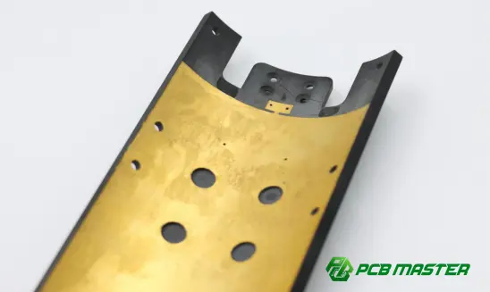
How Do You Choose the Right PCB for Different EV BMS Applications?
The choice of PCB for an EV Battery Management System (BMS) depends on the battery pack structure, voltage level, current demand, space availability and reliability requirements.
Priorities of EV BMS applications vary. For the high voltage battery pack, strong electrical isolation is required, for the small battery module, high density PCB solutions are required, and for high current applications, better thermal and current handling is required. Choosing the right EV BMS PCB can help strike the right balance between safety, performance, size and cost.
PCB priorities for high-voltage battery packs
High-voltage EV battery packs demand PCBs with superior electrical insulation, reliable insulation properties and robust safety design.
Modern EV battery systems are generally 400 V or 800 V, putting high standards on PCB design. Main PCB priorities are:
- High voltage isolation : adequate creepage and clearance distances to prevent electrical leakage and arcing between circuits.
- Trustworthy insulation materials : Automotive-grade PCB materials have stable performance against long-time voltage stress .
- Good safety design : Isolation structures, protective spacing and controlled PCB layout minimize the risk of electrical failures.
Due to the fact that a BMS PCB on an 800V battery platform must isolate high voltage monitoring circuits from low voltage communication circuits, There should be more attention on insulation distance and electrical safety compared with the low-voltage battery system.
PCB priorities for compact battery modules
Compact battery modules require PCBs with high density of circuits, small size and effective integration of components.
Many EV makers put the BMS electronics inside battery modules, to save space and simplify wiring. Important PCB considerations for these applications include:
- High density routing : To fit more circuits and components in a limited PCB spac
- Compact PCB design : Shrinking the size and weight of the battery management system.
- Reliable interconnections : Less connectors, less points of potential failure
HDI PCBs are often considered for compact BMS designs as smaller boards with micro vias and fine traces can support more functions. For example, a distributed BMS close to the single battery cells requires a smaller PCB than a centralized battery control unit.
PCB priorities for high-current applications
For EV BMS applications dealing with high currents, the PCB should have better heat dissipation, higher copper thickness and strong current carrying capacity.
The majority of BMS circuits are dealing with low level measurement signals, but there are some parts of the circuit that deal with higher current paths, such as battery protection and power distribution circuits. Some of the major requirements of PCB’s are:
- Thick Copper Layers : Lower Resistive Losses and Better Current Carrying Capacity.
- Better temperature control : Stops the temperature from getting too high when it is running.
- Optimized power routing : Verify that current is flowing safely in the designed paths.
In a BMS circuit that controls the battery disconnect devices, there can be high current when charging or in an emergency shutdown. A regular PCB may not have enough thermal capability, but a heavy copper PCB can improve reliability and prevent overheating.
A practical checklist for selecting an EV BMS PCB
When selecting the EV BMS PCB, the number of layers, material, copper weight, thermal performance, isolation capability and reliability requirements should be considered.
Engineers should take the following into account before choosing a PCB solution:
- Layers count : The circuit complexity, signal integrity and power distribution requirement determines the number of PCB layers.More advanced EV BMS designs use multilayer PCBs for additional routing flexibility.
- Material : Automotive grade FR-4 is used for most applications.If the PCB will be subject to higher temperatures or frequent thermal cycling, use high-Tg materials.
- Weight of copper : Monitoring lines (standard) copper thickness. Use heavy copper in high-current paths and power distribution areas.
- Thermal performance : Evaluate heat dissipation strategies like thermal vias, copper areas, and component location.
- Ability to separate : Make sure creepage distance, clearance distance and insulation design are adequate for the battery voltage level.
- Reliability specifications : Resistance to vibration, temperature range, service life, automotive standards
While not a PCB for an EV BMS has to be more than the smallest or the cheapest. The best PCB is one that is well matched to the specific battery architecture and offers the right combination of electrical performance, thermal management, safety and long term reliability.
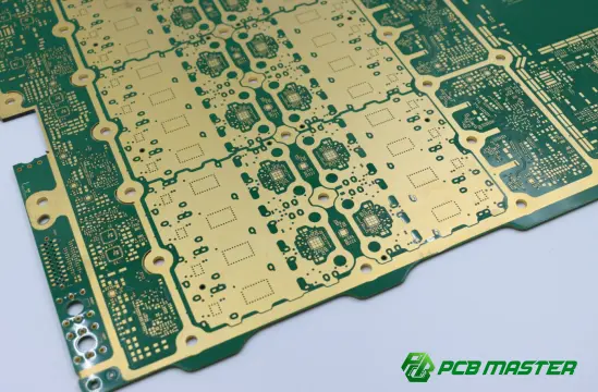
Conclusion
One of the most important steps in designing a reliable EV Battery Management System (BMS) is choosing the right PCB. The PCB affects the accuracy of the battery monitoring, electrical safety, thermal performance and long term reliability of the system. A good EV BMS PCB guarantees the battery pack to work efficiently and safely under different driving and charging scenarios.
The best solution for the PCB will depend on many factors such as the battery voltage, current requirements, available space for installation, thermal conditions and automotive durability expectations. Engineers can achieve a more robust and dependable BMS design by carefully evaluating the PCB type, material selection, layer stack-up, copper thickness and design requirements together.
EV BMS applications demand a combination of advanced engineering knowledge and manufacturing expertise; selecting an experienced PCB partner can help minimize design risks and improve manufacturing reliability. Leveraging automotive PCB solution expertise, PCBMASTER offers professional PCB manufacturing , material selection assistance, and DFM optimization for EV BMS projects to assist customers in building robust battery management solutions.
FAQs
What is the typical PCB layer count for an EV BMS?
Most of the EV BMS PCBs are 4 to 8 layers but more complex battery management system may require more layers. It depends upon the circuit complexity and performance requirements.
For many cases, a 4 layer PCB will be enough, such as for simple BMS designs that do not have many routing requirements. However, complex EV BMS solutions generally use 6 or 8 layer PCBs and need special layers for power, ground, signal routing and electromagnetic interference (EMI) control.
The number of layers is defined by the number of battery cells, communication interfaces, power circuits, thermal requirements and space. Routing at high density in a compact distributed BMS embedded in the battery modules may require a large number of layers for a small size PCB.
Can a standard FR-4 PCB be used in an electric vehicle BMS?
Because of their good balance of electrical isolation, mechanical toughness, thermal performance and cost, automotive grade FR-4 PCBs are a good fit for many EV BMS applications.
FR-4 is the most widely used PCB material for EV BMS builds. FR-4 is a common commercial material and may not meet all automotive requirements. In EV applications, FR-4 materials are used, which are generally of higher quality, having better properties, e.g.:
- Higher glass transition temperature (Tg) for better thermal stability.
- Better resistance to temperature cycling.
- More reliable performance under long-term automotive conditions.
If the BMS is designed to operate at higher temperatures, handle higher voltage stress, or meet specific electrical requirements, engineers may opt for high-Tg FR-4 or specialty laminates.
Does every EV BMS require an HDI PCB?
No. Not every EV BMS needs HDI PCBs. Typically, the BMS uses HDI technology if the circuit density is higher, the size is smaller or more sophisticated components are integrated.
Conventional multilayer PCBs are good for many applications of the EV BMS. Nevertheless, HDI PCBs are valuable in space-constrained applications such as:
- Battery modules with integrated BMS electronics.
- Compact automotive control units.
- Designs using fine-pitch IC packages.
HDI technology uses microvias and smaller traces to fit more circuits into a smaller area. While it offers design advantages, it complicates and increases the costs of manufacturing. So, engineers should choose HDI only when necessary in the application.
What is the most important PCB requirement for EV battery safety?
The most important PCB requirement for EV battery safety is to detect a short circuit and then cut off the power supply.
The most important PCB requirement for EV battery safety is reliable electrical isolation, particularly for high voltage battery systems.
An EV battery pack PCB needs to be able to keep circuits separate from each other so they don’t come into unwanted electrical contact at hundreds of volts. The main safety design features:
- Proper creepage and clearance distances.
- Reliable insulation materials.
- Isolation slots between high-voltage and low-voltage areas.
- Stable performance under temperature and environmental changes.
In addition to electrical isolation, another requirement is to accurately measure voltage and temperature, so that the BMS can recognize the abnormality of the battery in time. The EV BMS PCB design combines electrical safety, measurement accuracy and thermal reliability to guarantee battery system.
How does PCB quality affect the lifespan of an EV BMS?
PCB quality affects an EV BMS lifetime in terms of electrical stability, thermal performance, mechanical durability, and environmental stress tolerance.
A good quality PCB will ensure reliable connections and stable operation for years of vehicle use. Some of the problems with poor quality PCB can be:
- Signal errors caused by unstable connections.
- Overheating caused by poor thermal design.
- Cracks or solder failures caused by vibration.
- Reduced reliability caused by material degradation.
For example, an EV exposed to temperature fluctuations and vibration while driving needs a PCB capable of withstanding constant mechanical and thermal stress. The quality of the materials, correct manufacturing techniques and optimized PCB design increase the life of the BMS and overall reliability of the vehicle.
About the Author

Carol Luo
PCB Design EngineerI'm Carol, a PCB Engineer at PCBMASTER with experience in PCB design and manufacturing engineering since 2018. I focus on translating engineering requirements into reliable PCB solutions, with expertise in stack-up design, material selection, and design-for-manufacturing (DFM). I share practical engineering insights from real-world PCB design and production experience.
Visit Carol Luo's Profile

