







PCB Drilling Guidelines for Different FR-4 Materials: How to Optimize Hole Quality and Reliability
FR-4 is the most widely used material in PCB manufacturing because it offers a strong balance of electrical performance, mechanical stability, and cost efficiency. However, although FR-4 is often discussed as a single material category, it actually includes several different types, such as standard Tg FR-4, high Tg FR-4, halogen-free FR-4, high-frequency FR-4, heavy copper boards, and thin-core materials. Since each type has different resin systems, thermal characteristics, hardness, and structural properties, their drilling behavior can vary significantly during PCB fabrication.
As a result, using the same drilling process across all FR-4 materials can easily create manufacturing problems, including resin smear, rough hole walls, burrs, nail heading, delamination, excessive drill wear, and even drill breakage. Therefore, manufacturers must adjust drilling parameters, drill bit selection, chip removal strategies, and machine control according to the specific board material in order to maintain stable quality and production efficiency.
With extensive experience in manufacturing complex PCBs and PCBAs, PCBMASTER understands how different FR-4 materials respond to drilling processes under real production conditions. In the following sections, PCBMASTER will explain the key drilling considerations for different FR-4 board materials and share practical recommendations for improving drilling quality, reliability, and process stability.
What Problems Should Be Considered When Drilling Standard FR-4 PCB Materials?
Standard FR-4 is the most commonly used PCB substrate in the electronics industry, so its drilling process is relatively mature and stable. However, even though standard Tg FR-4 is easier to machine than high Tg or halogen-free materials, manufacturers still need to control drill selection, spindle speed, feed rate, chip removal, and hole wall cleanliness to avoid defects such as burrs, smear, and rough holes. At PCBMASTER, standard FR-4 drilling parameters are optimized based on board thickness, hole size, copper thickness, and production volume to ensure stable drilling quality and long drill life.
What Are the Material Characteristics and Processing Advantages of Standard FR-4?
Standard Tg FR-4 is easier to drill because its resin system is softer and less abrasive than many advanced PCB materials.
Common Parameters of Standard Tg FR-4
Standard FR-4 usually has a glass transition temperature (Tg) of around 130°C to 140°C. It combines woven fiberglass with epoxy resin, giving the board good mechanical strength and stable electrical insulation at a reasonable cost.
Compared with high Tg or high-frequency materials, standard FR-4 is less brittle and creates lower cutting resistance during drilling. This means the drill bit experiences less stress and slower wear. For example, many consumer electronics PCBs, LED boards, and industrial control boards still use standard FR-4 because it offers stable drilling performance and lower production cost.
Why Does Standard FR-4 Have a Wider Processing Window?
Standard FR-4 is more forgiving during drilling because its resin softens more evenly under heat and produces fewer severe chip removal problems. As a result, manufacturers can use a wider range of spindle speeds and feed rates without causing serious hole defects.
For example:
- Slight parameter changes usually do not cause immediate drill breakage.
- The risk of severe smear is lower than with halogen-free FR-4.
- Drill bit wear develops more slowly than with high Tg materials.
This wider process window helps PCB factories improve drilling efficiency while maintaining stable hole quality.
What Drill Bit Selection Is Recommended for Standard FR-4?
Standard carbide drill bits are usually sufficient for standard FR-4 drilling, but tool condition must be monitored carefully.
Application of Standard Carbide Drill Bits
Most PCB manufacturers use solid tungsten carbide drill bits for standard FR-4 because they provide high hardness, stable cutting performance, and good wear resistance.
Typical drill bit features include:
- Sharp cutting edges for smoother hole walls
- Strong rigidity for accurate hole positioning
- Good heat resistance during high-speed drilling
At PCBMASTER, drill geometry is selected based on hole diameter, board thickness, and stack-up structure. Smaller holes usually require sharper drill points and more frequent replacement intervals.
How Can Manufacturers Identify Drill Bit Wear?
Drill bit wear directly affects hole quality. A worn drill may produce:
- Rough hole walls
- Excessive resin smear
- Burrs around hole openings
- Increased drill temperature
- Hole size deviation
Operators typically inspect drill wear using microscopes or automated tool monitoring systems. In high-volume PCB production, drill life is tracked by hit count, meaning the number of holes drilled before replacement.
PCBMASTER’s Drill Life Management Experience
PCBMASTER uses drill life control standards based on:
- Board material type
- Hole diameter
- Copper thickness
- Total drilling depth
For example, smaller drill bits used for microvias are replaced much earlier than large-diameter drills because they wear faster and are more likely to break. This preventive management helps maintain consistent drilling quality and reduces production risk.
How Can Standard FR-4 Drilling Parameters Be Set More Stably?
Stable drilling requires balancing spindle speed, feed rate, and drilling temperature according to board structure and hole size.
Recommended Spindle Speed Range
Standard FR-4 is compatible with relatively high spindle speeds because the material is not extremely hard. High-speed drilling helps produce cleaner cuts and smoother hole walls.
In most PCB factories:
- Small holes use higher spindle speeds
- Larger holes use lower spindle speeds
- Thick boards may require reduced speed to control heat
Excessive speed, however, may still increase resin softening and smear if chip removal becomes insufficient.
Recommended Feed Rate Control
Feed rate controls how quickly the drill moves into the material. Proper feed rates help maintain cutting efficiency while preventing excessive heat buildup.
If feed is too low:
- Friction increases
- Drill temperature rises
- Resin smear becomes worse
If feed is too high:
- Drill stress increases
- Hole roughness may worsen
- Drill breakage risk rises
PCBMASTER adjusts feed rates according to hole aspect ratio and copper thickness to maintain stable cutting conditions.
How Can Efficiency and Hole Wall Quality Be Balanced?
Higher drilling speed improves productivity, but overly aggressive settings may damage hole quality. Therefore, manufacturers must balance:
- Production efficiency
- Drill lifespan
- Hole wall smoothness
- Burr control
For example, a slightly lower spindle speed combined with optimized feed can often improve overall yield and reduce drill replacement cost.
How Can Burrs and Resin Smear Be Reduced During Standard FR-4 Drilling?
Effective chip removal, sharp drill bits, and proper cleaning control are the main ways to reduce burrs and smear.
Why Is the Vacuum System Important?
During drilling, fiberglass dust and resin chips must be removed quickly from the hole. A strong vacuum system helps:
- Reduce heat buildup
- Prevent chip blockage
- Improve hole wall cleanliness
- Extend drill life
Poor dust collection often causes resin smear and rough hole walls because trapped chips increase friction inside the hole.
Why Must Drill Bits Remain Sharp?
Sharp drill bits cut cleanly through fiberglass and resin with lower cutting force. In contrast, dull drills create more friction and heat, leading to:
- Smear around inner copper layers
- Burrs at hole entry and exit
- Rougher hole walls
Regular drill replacement is one of the simplest ways to maintain stable PCB drilling quality.
How Is Hole Wall Cleanliness Controlled?
After drilling, PCB manufacturers usually inspect hole walls for:
- Resin residue
- Burr formation
- Fiber pull-out
- Copper exposure quality
PCBMASTER combines optimized drilling parameters with controlled desmear and cleaning processes to ensure clean hole walls before plating. This is especially important for multilayer PCBs, where poor hole cleanliness can affect plating reliability and long-term electrical performance.
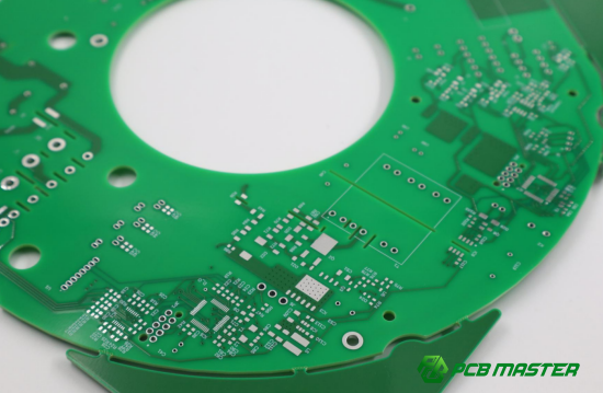
What Are the Key Control Points When Drilling High Tg FR-4 PCB Materials?
High Tg FR-4 is widely used in automotive electronics, industrial control systems, servers, and high-reliability PCBs because it can withstand higher operating temperatures than standard FR-4. However, its higher hardness and stronger thermal resistance also make drilling more difficult. Compared with standard FR-4, high Tg materials generate more drill wear, higher cutting stress, and greater risk of rough hole walls or nail heading defects. At PCBMASTER, high Tg PCB drilling processes are optimized through strict drill selection, parameter adjustment, and machine stability control to maintain reliable hole quality.
Why Is High Tg FR-4 More Difficult to Drill?
High Tg FR-4 is harder and more brittle, so it creates higher cutting resistance and faster drill wear during PCB drilling.
High Hardness and Brittleness Characteristics
High Tg FR-4 typically has a Tg value above 170°C. Its resin system remains stable at higher temperatures, but this also makes the material harder and less flexible during drilling.
Compared with standard FR-4:
- Cutting force becomes higher
- The material is less forgiving
- Hole wall cracking risk increases
- Drill stress becomes more concentrated
For example, when drilling multilayer automotive PCBs, high Tg boards are more likely to produce rough hole walls if drilling parameters are too aggressive.
How Does High Tg FR-4 Affect Drill Wear?
Because high Tg materials are more abrasive, drill bits wear faster during high-speed drilling. A dull drill quickly increases:
- Hole wall roughness
- Resin smear
- Nail heading defects
- Drill breakage risk
This is why high Tg PCB production usually requires shorter drill life cycles and more frequent tool inspection.
Why Is High Tg Material Stable in High-Temperature Environments?
The advantage of high Tg FR-4 is its ability to maintain structural stability under thermal stress. During soldering or high-power operation, the material resists softening better than standard FR-4.
However, during drilling, this heat resistance means the resin does not soften easily, so the drill experiences greater mechanical resistance instead of softer cutting action.
What Type of PCB Drill Bit Is Suitable for High Tg FR-4?
High Tg FR-4 requires stronger, sharper, and more wear-resistant drill bits than standard FR-4.
Why Is High-Strength Cutting Edge Design Important?
High Tg drilling creates greater impact force on the drill tip. Therefore, drill bits need reinforced cutting edges to resist:
- Edge chipping
- Premature wear
- Drill cracking
- Sudden breakage
Strong edge geometry helps maintain stable cutting performance even during long production runs.
Why Are Wear-Resistant Coatings Important?
Special coatings improve drill durability when cutting hard PCB materials. Common coating benefits include:
- Reduced friction
- Lower heat generation
- Better wear resistance
- Longer tool life
For example, coated carbide drills often last significantly longer when drilling high Tg multilayer PCBs compared with uncoated tools.
What Drill Point Structure Works Best for High Tg Materials?
High Tg PCB drilling usually uses:
- Sharper cutting angles
- Optimized chip evacuation grooves
- Reinforced drill tips
These designs reduce cutting resistance while improving chip removal. At PCBMASTER, drill geometry is selected according to hole diameter, stack thickness, and copper layer count.
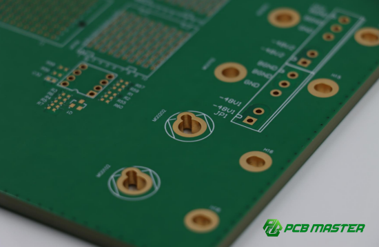
How Should High Tg FR-4 Drilling Parameters Be Optimized?
High Tg drilling parameters should reduce heat and cutting stress while maintaining stable chip removal.
Why Should Spindle Speed Be Reduced Slightly?
Although high-speed drilling improves productivity, excessive spindle speed increases:
- Friction heat
- Drill wear
- Hole wall damage
- Resin burning risk
Therefore, high Tg PCB drilling usually uses slightly lower spindle speed than standard FR-4 to reduce thermal stress on both the material and the drill bit.
What Happens If Feed Rate Is Too High or Too Low?
Feed rate must remain balanced.
If feed is too low:
- Friction increases
- Resin overheating becomes worse
- Drill wear accelerates
If feed is too high:
- Drill stress rises sharply
- Nail heading risk increases
- Drill breakage becomes more likely
PCBMASTER adjusts feed settings according to hole size and board thickness to maintain stable cutting force.
How Can Heat Accumulation Be Reduced?
Heat control is critical during high Tg drilling. Common methods include:
- Reducing spindle speed slightly
- Improving chip evacuation
- Limiting stack height
- Using sharp drill bits
- Increasing vacuum efficiency
For deep-hole drilling, periodic peck drilling may also help improve cooling and chip removal.
How Can Nail Heading and Rough Hole Walls Be Reduced in High Tg FR-4?
Stable cutting force and low machine vibration are the key factors for improving hole wall quality.
How Can Cutting Force Be Controlled?
Lower cutting force helps reduce copper deformation and hole wall damage. Manufacturers usually achieve this by:
- Using sharp drills
- Optimizing feed rates
- Reducing excessive spindle speed
- Controlling stack thickness
Lower cutting force is especially important for multilayer PCBs with dense inner copper layers.
Why Is Reducing Spindle Runout Important?
Spindle runout means the drill rotates unevenly. Even small vibration can cause:
- Hole position deviation
- Rough hole walls
- Drill edge chipping
- Nail heading around inner layers
Because high Tg materials are harder, they are more sensitive to vibration than standard FR-4.
PCBMASTER’s Experience in High Tg PCB Drilling
PCBMASTER uses strict spindle calibration and drill monitoring systems for high Tg PCB production. Drill replacement intervals are shortened for smaller holes and thick multilayer boards to maintain stable hole wall quality and reduce defect rates during mass production.
How Should Drilling Machine Conditions Be Controlled for High Tg PCB Materials?
High Tg PCB drilling requires highly stable drilling equipment with precise spindle control and temperature monitoring.
What Spindle Accuracy Is Required?
High Tg drilling requires minimal spindle runout because harder materials amplify vibration problems. High-precision spindles help:
- Maintain hole accuracy
- Reduce drill wear
- Improve hole wall smoothness
- Lower breakage risk
This becomes especially important for small-diameter holes and HDI PCBs.
Why Is Vibration Control Important?
Machine vibration directly affects drilling stability. Excessive vibration may cause:
- Delamination
- Rough hole walls
- Drill edge damage
- Inconsistent hole sizes
PCBMASTER regularly maintains drilling equipment to ensure stable spindle rotation and positioning accuracy.
How Is Drilling Temperature Monitored?
Temperature monitoring helps prevent overheating during continuous drilling. Manufacturers usually monitor:
- Drill wear condition
- Hole wall appearance
- Chip color and shape
- Machine operating temperature
If overheating is detected, drilling parameters are adjusted immediately to prevent damage to the PCB material and drill bit.
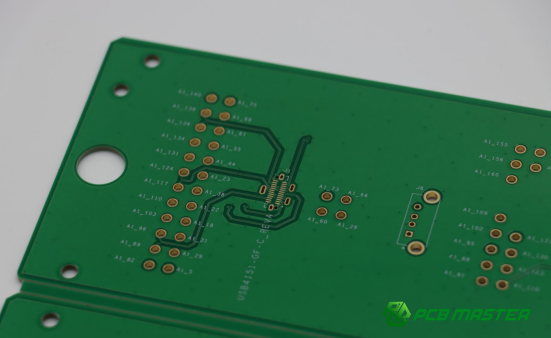
Why Does Halogen-Free FR-4 Produce More Resin Smear During PCB Drilling?
Halogen-free FR-4 is widely used in environmentally friendly electronics because it avoids brominated flame retardants. However, compared with standard FR-4, halogen-free materials are usually tougher, stickier, and less thermally conductive. These differences make chip removal more difficult during drilling and increase the risk of resin smear, drill clogging, rough hole walls, and drill breakage. At PCBMASTER, halogen-free PCB drilling is carefully controlled through optimized drill geometry, drilling parameters, and vacuum systems to maintain stable hole quality.
What Material Property Changes Exist in Halogen-Free FR-4?
Halogen-free FR-4 uses different flame retardants, which change the resin behavior during drilling.
Characteristics of Phosphorus- and Nitrogen-Based Flame Retardants
Traditional FR-4 uses bromine-based flame retardants, while halogen-free FR-4 commonly uses phosphorus- or nitrogen-based systems. These new materials improve environmental compliance but also change machining behavior.
Compared with standard FR-4:
- The resin becomes tougher
- Chips become stickier
- Cutting resistance may increase
- Heat dissipation can become weaker
This is why halogen-free PCB drilling often requires different drilling strategies.
How Does Resin Toughness Change?
Halogen-free resin is usually less brittle and more elastic during cutting. Instead of breaking into small chips easily, the material may stretch and stick to the drill surface.
This increases:
- Chip adhesion
- Drill temperature
- Hole wall smear
- Risk of drill clogging
For example, small-hole drilling in halogen-free multilayer PCBs often produces longer resin chips than standard FR-4.
How Does Thermal Conductivity Affect Drilling?
Some halogen-free materials transfer heat less efficiently. As a result, heat stays around the drill tip longer during high-speed drilling.
This can lead to:
- Resin softening
- Increased smear
- Faster drill wear
- Poor hole wall quality
Proper heat control therefore becomes very important when drilling halogen-free PCB materials.
Why Is Chip Clogging More Common in Halogen-Free FR-4 Drilling?
Tougher resin chips stick more easily to the drill and are harder to remove from the hole.
Why Do Resin Chips Stick to the Drill?
During drilling, halogen-free resin can become soft and adhesive under heat. Instead of leaving the hole smoothly, chips may stick to:
- The drill flute
- The drill tip
- The hole wall
This sticky behavior reduces chip evacuation efficiency and increases friction inside the hole.
What Problems Are Caused by Poor Chip Removal?
Poor chip evacuation creates several drilling problems:
- Drill overheating
- Faster drill wear
- Hole wall roughness
- Heavy resin smear
- Drill breakage
If chips remain trapped inside the hole, cutting force increases rapidly and drilling stability decreases.
Why Are Small Holes and Deep Holes Higher Risk?
Small-diameter holes and high aspect ratio holes have less space for chip evacuation. This makes clogging much more likely in halogen-free PCB drilling.
For example:
- Microvias generate heat faster
- Deep holes trap chips more easily
- Long drilling paths increase friction
PCBMASTER therefore applies stricter drilling controls for small-hole halogen-free PCB production.
How Should Halogen-Free FR-4 Drilling Parameters Be Adjusted?
Halogen-free PCB drilling usually requires slightly higher spindle speed, optimized feed rate, and controlled peck drilling.
Why Is Higher Spindle Speed Often Used?
Slightly higher spindle speed helps cut tough resin fibers more cleanly and improves chip separation.
Benefits include:
- Cleaner cutting action
- Reduced chip tearing
- Better chip evacuation
- Lower resin adhesion
However, speed increases must remain controlled to avoid excessive heat buildup.
What Is the Purpose of Increasing Feed Rate?
A moderate feed increase helps reduce the amount of time the drill rubs against the material. This lowers friction heat and reduces resin sticking.
If feed is too low:
- Friction rises
- Chips become softer
- Smear becomes worse
Balanced feed settings help maintain stable drilling performance.
How Does Peck Drilling Help?
Peck drilling means the drill periodically retracts during drilling. This strategy helps:
- Remove trapped chips
- Reduce drill temperature
- Improve airflow
- Lower clogging risk
PCBMASTER often uses peck drilling for:
- Deep holes
- Small-diameter holes
- Thick multilayer halogen-free PCBs
How Can Chip Evacuation Be Improved in Halogen-Free FR-4 Drilling?
Proper drill flute design and strong vacuum suction are critical for stable chip removal.
Why Is Drill Flute Design Important?
Optimized drill flute geometry improves the movement of chips out of the hole. Halogen-free PCB drilling often benefits from:
- Larger flute space
- Smoother chip channels
- Improved cutting edge geometry
These features reduce chip accumulation and lower drilling temperature.
Why Is the Vacuum System So Important?
Strong vacuum suction removes resin dust and chips before they build up around the drill.
A high-efficiency vacuum system helps:
- Reduce smear
- Prevent drill clogging
- Lower heat buildup
- Improve hole cleanliness
Weak suction is one of the main causes of poor drilling quality in halogen-free PCB production.
PCBMASTER’s Chip Removal Control Recommendations
PCBMASTER combines:
- Optimized spindle speed
- Controlled feed rate
- Advanced vacuum systems
- Frequent drill replacement
This process helps maintain stable chip evacuation even during high-volume halogen-free PCB manufacturing.
How Can Resin Smear Residue Be Reduced in Halogen-Free FR-4?
Clean drilling, proper desmear processing, and careful hole inspection are necessary to control smear residue.
What Should Be Controlled During Post-Drilling Cleaning?
After drilling, manufacturers should remove:
- Resin residue
- Fiberglass dust
- Copper particles
- Loose burrs
Proper cleaning improves plating reliability and reduces electrical connection problems later in production.
Why Is Desmear Processing Important?
Desmear is a chemical process that removes resin residue from hole walls after drilling. Because halogen-free smear can be more difficult to remove than standard FR-4 smear, desmear control becomes especially important.
Proper desmear processing helps:
- Expose clean inner-layer copper
- Improve plating adhesion
- Reduce reliability failures
How Are Hole Walls Inspected?
Manufacturers usually inspect:
- Hole wall smoothness
- Resin residue levels
- Copper exposure quality
- Delamination risk
At PCBMASTER, hole wall quality is checked through microscope inspection and process verification to ensure reliable multilayer PCB performance after plating.
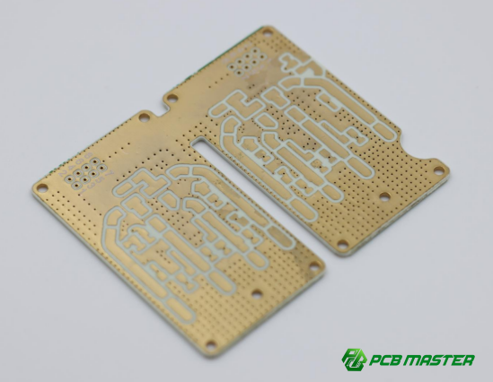
How Can Signal Performance Be Maintained When Drilling High-Frequency FR-4 PCB Materials?
High-frequency FR-4 materials are widely used in RF PCBs, communication systems, automotive radar, antennas, and high-speed digital applications. These materials are designed to reduce signal loss, but they are also more sensitive to drilling quality than standard FR-4. Poor drilling can increase signal attenuation, impedance instability, and reliability problems. At PCBMASTER, high-frequency PCB drilling focuses on low cutting force, smooth hole walls, stable machine accuracy, and strict cleanliness control to protect electrical performance.
What Special Processing Requirements Do High-Frequency FR-4 Materials Have?
High-frequency FR-4 materials require cleaner drilling, lower mechanical stress, and smoother hole walls to maintain stable signal transmission.
Characteristics of Low Dk and Low Df Materials
High-frequency PCB materials are designed with low dielectric constant (Dk) and low dissipation factor (Df) . These properties help signals travel faster and reduce energy loss during transmission.
Compared with standard FR-4:
- Signal loss is lower
- Impedance control is more sensitive
- Hole wall quality becomes more critical
Even small drilling defects can affect high-speed signal performance in RF and microwave PCBs.
How Do Special Fillers Affect Drilling?
Many high-frequency FR-4 materials contain ceramic fillers or modified resin systems to improve electrical performance. These fillers can make the material:
- Harder to cut
- More brittle
- More abrasive to drill bits
As a result, drill wear may increase faster than with ordinary FR-4 materials.
Why Do High-Frequency PCBs Require Better Hole Wall Quality?
In high-frequency circuits, signal current flows along the copper surface. Rough hole walls increase electrical resistance and signal loss.
For this reason, high-frequency PCB drilling must minimize:
- Hole wall roughness
- Burrs
- Resin smear
- Copper deformation
Smooth hole walls help maintain stable signal integrity and impedance consistency.
Why Is Hole Wall Roughness More Important for High-Frequency PCBs?
Rough hole walls increase signal loss and interfere with high-frequency signal transmission.
How Does Hole Wall Roughness Affect Signal Loss?
When copper plating follows a rough drilled surface, the electrical path becomes uneven. High-frequency signals lose more energy when traveling through rough conductive surfaces.
This can cause:
- Higher insertion loss
- Reduced signal strength
- Unstable transmission performance
For example, in 5G communication PCBs, rough vias can directly reduce signal quality.
How Does Skin Effect Influence High-Frequency Signals?
At high frequencies, electrical current mainly travels along the outer surface of the conductor. This is called the skin effect.
Because of this:
- Smooth copper surfaces become very important
- Small surface defects increase resistance
- Hole wall quality directly affects signal flow
Even microscopic drilling defects can influence high-speed PCB performance.
How Do Micro Burrs Affect Impedance?
Tiny burrs or irregular copper edges can disturb controlled impedance structures. This may cause:
- Signal reflection
- Noise increase
- Impedance mismatch
- Reduced RF stability
High-frequency PCB manufacturing therefore requires stricter drilling quality control than standard digital PCBs.
What Drilling Parameters Are Suitable for High-Frequency FR-4?
High-frequency PCB drilling should use low cutting force, controlled heat generation, and stable chip evacuation.
Why Is Low Cutting Force Important?
Excessive cutting force may damage delicate resin systems or special fillers inside high-frequency materials.
Lower cutting force helps:
- Reduce delamination risk
- Improve hole wall smoothness
- Protect inner-layer structure
- Reduce burr formation
Sharp drill bits and optimized feed rates are commonly used to lower drilling stress.
Why Must Heat Generation Be Controlled?
High drilling temperature may soften resin, damage fillers, or increase smear. This affects both electrical and mechanical performance.
To reduce heat:
- Spindle speed is carefully optimized
- Feed rate is balanced
- Drill wear is monitored closely
- Vacuum systems remove chips efficiently
Stable temperature control is especially important for multilayer RF PCBs.
How Can Chip Evacuation and Hole Smoothness Be Balanced?
Good chip evacuation prevents overheating, but aggressive chip removal may increase cutting damage. Manufacturers must balance:
- Efficient chip removal
- Smooth hole walls
- Stable cutting force
- Minimal vibration
PCBMASTER adjusts drilling parameters according to board thickness, via size, and material structure to maintain stable high-frequency PCB quality.
How Can Delamination Risk Be Reduced During High-Frequency PCB Drilling?
Lower mechanical stress and stable board support help prevent layer separation during drilling.
How Can Mechanical Stress Be Controlled?
High-frequency PCB materials may be more brittle than standard FR-4. Excessive drilling force can separate resin layers or damage internal structures.
Manufacturers reduce stress by:
- Using sharp drill bits
- Reducing excessive feed force
- Optimizing spindle speed
- Controlling drill wear
Stable drilling force helps protect multilayer bonding integrity.
Why Should Stack Height Be Optimized?
Drilling too many panels together increases:
- Heat buildup
- Mechanical load
- Vibration
- Hole quality variation
For high-frequency PCB drilling, stack height is usually reduced compared with standard FR-4 production.
Why Are Material Support and Clamping Important?
Proper backup boards and clamping systems help stabilize thin or fragile high-frequency materials during drilling.
Good support reduces:
- Board movement
- Entry burrs
- Exit tearing
- Hole position deviation
PCBMASTER uses controlled panel support systems for high-frequency PCB production to improve drilling consistency.
How Does PCBMASTER Improve High-Frequency PCB Drilling Quality?
PCBMASTER combines precision drilling equipment, roughness control, and specialized process validation for high-frequency PCB manufacturing.
How Does High-Precision Drilling Equipment Help?
High-frequency PCBs require excellent drilling accuracy. PCBMASTER uses high-precision drilling machines with:
- Low spindle runout
- Stable positioning accuracy
- Controlled vibration
- High-speed processing capability
These systems help maintain smooth hole walls and accurate via positioning.
What Hole Wall Roughness Standards Are Controlled?
PCBMASTER closely monitors:
- Hole wall smoothness
- Burr formation
- Resin smear levels
- Copper exposure quality
Strict roughness control helps improve signal integrity in RF and high-speed PCB applications.
What Is Included in PCBMASTER’s High-Frequency PCB Validation Process?
Before mass production, PCBMASTER verifies:
- Drill parameter stability
- Hole wall quality
- Material compatibility
- Signal performance reliability
This process helps ensure that high-frequency PCB drilling remains stable across different material types and production volumes.
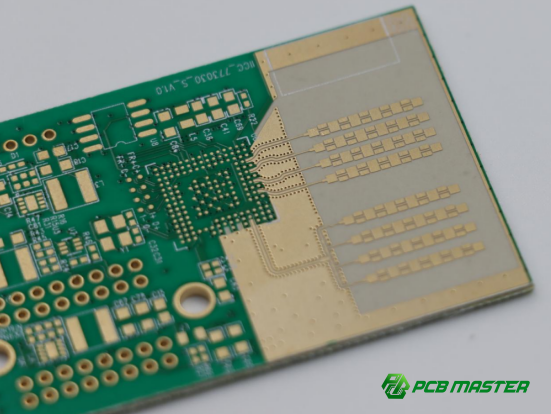
Why Do Thick Copper PCBs Break Drills More Easily During Drilling?
Thick copper PCB drilling is one of the most challenging processes in PCB manufacturing because the drill must pass through very hard copper layers before reaching the substrate. Compared with standard FR-4, 3oz or 4oz copper boards create much higher cutting resistance, stronger impact force, and faster tool wear. These conditions significantly increase the risk of drill breakage, copper burrs, and hole quality instability. At PCBMASTER, thick copper drilling is controlled through optimized drill geometry, reduced mechanical stress, and strict tool life management.
What Are the Main Processing Challenges in Thick Copper PCB Drilling?
Thick copper layers increase cutting force, chip congestion, and tool load, making drilling more unstable.
Impact Force from Thick Copper Layers
When the drill first contacts thick copper, it experiences a sudden high-impact force. This is much stronger than standard copper layers.
This can cause:
- Drill tip chipping
- Entry burrs
- Hole position deviation
- Instant tool stress increase
For example, in 4oz copper boards, the first contact point is often where most drill failures occur.
Why Is Copper Chip Removal Difficult?
Thick copper produces heavy and dense chips during drilling. These chips are harder to evacuate from the hole.
Poor chip removal leads to:
- Heat accumulation
- Drill clogging
- Increased friction
- Faster wear
If chips stay inside the hole, they act like abrasive particles and damage the drill edges.
Why Does Drill Load Increase So Quickly?
As the drill penetrates thick copper, resistance builds up very quickly. This sudden load increase can exceed the tool’s mechanical limit if parameters are not controlled properly.
This results in:
- Drill overload
- Sudden breakage
- Reduced tool life
- Unstable hole quality
What Type of Drill Bits Are Suitable for Thick Copper PCBs?
Thick copper PCBs require reinforced, high-strength drill bits with optimized cutting angles and better chip evacuation design.
Why Are 135° and 140° Drill Point Angles Better?
A 135°–140° drill point provides stronger tip support and better impact resistance.
Benefits include:
- Reduced tip chipping
- Better penetration through copper
- Lower entry stress
- Improved stability in thick copper drilling
Compared with standard 118° drills, these angles are more suitable for heavy copper PCB drilling.
What Is the Role of Reinforced Chisel Edge Design?
The chisel edge is the center part of the drill tip. In thick copper drilling, this area takes the highest stress.
A reinforced design helps:
- Distribute cutting force evenly
- Reduce center wear
- Improve drill stability
- Lower breakage risk
This is especially important in high-layer industrial PCBs.
Why Are Special Chip Flute Designs Needed?
Thick copper generates heavy chips, so drill flutes must provide enough space for fast evacuation.
Improved flute design helps:
- Prevent chip clogging
- Reduce heat buildup
- Maintain smooth cutting
- Extend tool life
PCBMASTER selects flute designs based on copper thickness and hole diameter to ensure stable production.
How Should Drilling Parameters Be Set for Thick Copper PCBs?
Thick copper drilling requires lower speed, controlled feed, and sometimes step-by-step cutting to reduce stress.
Why Must Spindle Speed Be Reduced?
Lower spindle speed reduces impact force when the drill enters thick copper.
This helps:
- Reduce drill tip damage
- Lower heat generation
- Improve tool stability
- Prevent sudden breakage
Too high speed increases friction and accelerates wear.
Why Is Feed Rate Control Important?
Feed rate must be carefully balanced.
If feed is too high:
- Drill overload occurs
- Breakage risk increases
If feed is too low:
- Friction increases
- Heat buildup worsens
- Burr formation may increase
PCBMASTER adjusts feed rate based on copper thickness and hole diameter to maintain stable drilling force.
What Is a Step Drilling Strategy?
Step drilling means the process is divided into stages instead of cutting all at once.
For thick copper:
- First stage penetrates copper slowly
- Second stage continues into substrate
- Sometimes additional pecking is used
This reduces stress concentration and improves tool life.
How Can Nail Heading and Copper Burrs Be Reduced in Thick Copper PCBs?
Controlling deformation, maintaining sharp tools, and optimizing cutting conditions help reduce defects.
How Can Copper Layer Deformation Be Controlled?
Copper deformation (nail heading) happens when excessive force pushes copper into the hole.
To reduce it:
- Lower feed rate slightly
- Use stronger drill tip geometry
- Ensure stable clamping
- Reduce vibration
This helps maintain clean inner layer connections.
How Can Hole Entry and Exit Burrs Be Reduced?
Burrs occur when copper tears instead of being cut cleanly.
Reduction methods include:
- Using sharp drill bits
- Optimizing spindle speed
- Supporting PCB with proper backing boards
- Keeping tools within correct wear limits
Clean cutting edges reduce burr formation significantly.
Why Is Drill Sharpness So Important?
A sharp drill cuts copper cleanly with less force. A dull drill increases:
- Burr size
- Heat generation
- Hole wall roughness
- Breakage risk
Regular tool replacement is essential in thick copper PCB production.
How Can Drill Life Be Controlled in Thick Copper PCB Drilling?
Drill life is controlled through wear monitoring, scheduled replacement, and stable process management.
What Are the Wear Characteristics in Thick Copper Drilling?
Thick copper causes:
- Fast edge wear
- Tip chipping
- Flute abrasion
- Rapid performance decline
Compared with standard FR-4, tool life is significantly shorter.
Why Is Tool Replacement Scheduling Important?
If drills are used too long:
- Breakage risk increases sharply
- Hole quality becomes unstable
- Production defects rise
Therefore, drill replacement is usually based on:
- Hit count (number of holes)
- Copper thickness
- Hole diameter
PCBMASTER’s Drill Breakage Prevention System
PCBMASTER uses a structured control system including:
- Real-time tool wear tracking
- Copper thickness-based drill life standards
- Preventive replacement scheduling
- Process parameter optimization
This approach significantly reduces drill breakage risk and improves yield in thick copper PCB manufacturing.
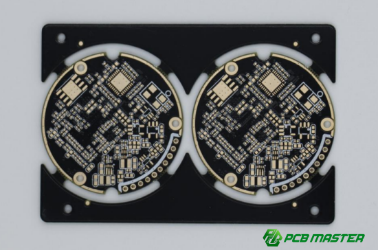
How Can PCB Deformation Be Prevented During Thin and Ultra-Thin PCB Drilling?
Thin and ultra-thin PCB drilling is highly sensitive because the board has very low mechanical strength. Even small changes in pressure, temperature, or clamping force can cause bending, hole misalignment, tearing, or burr formation. Compared with standard FR-4 boards, thin PCB drilling requires stricter control of support materials, drilling parameters, and fixture stability. At PCBMASTER, ultra-thin PCB drilling is managed through reinforced support systems, optimized cutting conditions, and precise alignment control to ensure stable hole quality.
Why Do Thin PCBs More Easily Cause Hole Position Deviation?
Thin PCBs lack rigidity, so they deform easily during drilling, leading to position errors and unstable hole quality.
Why Is Low Board Rigidity a Problem?
Thin PCB materials (<0.8mm or <0.4mm) cannot resist drilling force effectively. When the drill contacts the board, it may cause:
- Board bending
- Local vibration
- Hole position shift
- Irregular hole shape
For example, in LED light strips and wearable devices, thin boards often show slight misalignment if not properly supported.
How Does Thermal Deformation Affect Drilling Accuracy?
During high-speed drilling, heat is generated at the contact point. Thin boards absorb this heat unevenly, which can lead to:
- Local expansion
- Slight warping
- Dimensional instability
This affects precise hole positioning, especially in dense via designs.
Why Is Unstable Clamping a Risk?
If the PCB is not firmly fixed:
- The board may move during drilling
- Vibration increases
- Hole accuracy decreases
PCBMASTER uses controlled vacuum clamping systems to ensure stable positioning during thin PCB drilling.
Why Are Backup and Cover Boards Critical in Thin PCB Drilling?
Support materials prevent bending, reduce burrs, and improve drilling stability for thin PCB processing.
How Does Aluminum Backing Improve Stability?
Aluminum backing plates provide a strong and flat support surface under the PCB.
They help:
- Prevent board bending
- Reduce drill exit deformation
- Improve hole position accuracy
- Stabilize drilling pressure
This is especially important for ultra-thin flexible rigid boards.
Why Is Phenolic Backup Board Important for Exit Quality?
Phenolic boards (bakelite-type materials) support the drill exit area and reduce tearing.
They help:
- Reduce exit burrs
- Prevent fiber pull-out
- Improve hole roundness
Without proper backup, thin PCB exit holes often appear rough or torn.
How Do Backup Boards Help Heat Dissipation?
Support materials also help absorb and distribute drilling heat.
Benefits include:
- Lower thermal stress on PCB
- Reduced resin softening
- Improved hole wall quality
How Should Drilling Parameters Be Optimized for Thin PCBs?
Thin PCB drilling requires high speed, controlled feed, and minimal drill contact time.
Why Is High Spindle Speed Used?
High spindle speed helps:
- Reduce cutting force per rotation
- Improve drilling smoothness
- Minimize mechanical stress
For thin PCBs, smoother cutting is more important than deep force penetration.
What Is the Logic Behind Higher Feed Rates?
A properly controlled higher feed rate reduces the time the drill interacts with the board.
This helps:
- Reduce heat buildup
- Prevent board deformation
- Lower smear risk
However, feed must not be too high, or it may tear the board.
Why Must Dwell Time Be Minimized?
Dwell time means the drill staying in one position too long.
Reducing it helps:
- Prevent local overheating
- Avoid resin melting
- Improve hole cleanliness
PCBMASTER optimizes cycle time to ensure minimal contact stress during thin PCB drilling.
How Can Hole Entry and Exit Quality Be Improved in Thin PCBs?
Clean cutting, proper support, and stable drilling motion help improve hole quality.
How Can Exit Tearing Be Prevented?
Exit tearing happens when the drill leaves the board without support.
Prevention methods include:
- Using backup boards
- Optimizing feed rate
- Keeping drill sharp
- Ensuring stable clamping
This is especially important for ultra-thin FR-4 and flex-rigid PCBs.
How Can Burr Formation Be Reduced?
Burrs are caused by fiber tearing instead of clean cutting.
Reduction methods:
- Use sharp drill bits
- Maintain stable spindle speed
- Improve chip evacuation
- Avoid excessive pressure
How Can Hole Consistency Be Improved?
Consistency depends on stable process control.
Key methods:
- Uniform stack setup
- Controlled drilling parameters
- Stable machine vibration levels
PCBMASTER uses standardized drilling profiles to maintain consistent hole quality across large production batches.
How Does PCBMASTER Ensure High Precision in Ultra-Thin PCB Drilling?
PCBMASTER uses precision fixtures, calibration systems, and specialized thin-board experience to maintain stable accuracy.
How Do High-Flatness Fixtures Help?
High-flatness fixtures ensure the PCB remains completely level during drilling.
They help:
- Prevent bending
- Improve hole alignment
- Reduce vibration errors
This is essential for ultra-thin PCB manufacturing.
What Is Automatic Positioning Calibration?
Automatic calibration systems ensure the drill aligns precisely with the PCB design data.
Benefits include:
- Improved hole accuracy
- Reduced misalignment defects
- Stable mass production performance
PCBMASTER’s Experience in Ultra-Thin PCB Manufacturing
PCBMASTER has extensive experience in processing:
- Flexible rigid boards
- Ultra-thin FR-4 (<0.4mm)
- High-density small-hole designs
Through optimized support systems and strict process control, PCBMASTER ensures high yield and stable quality in ultra-thin PCB drilling applications.
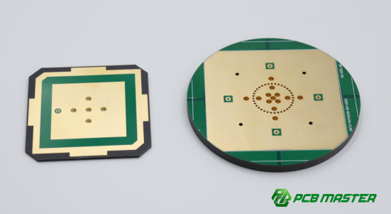
Which Key Factors Determine Final Quality in PCB Drilling Processes?
PCB drilling quality is not determined by a single factor. Instead, it is the combined result of drill bit performance, drilling parameters, machine condition, and environmental control. Even small deviations in any of these areas can lead to defects such as burrs, smear, hole misalignment, rough walls, or drill breakage. At PCBMASTER, final drilling quality is controlled through a full-process system that integrates tool management, parameter optimization, and equipment monitoring to ensure stable PCB hole quality in mass production.
How Does Drill Bit Performance Affect PCB Drilling Stability?
Drill bit quality directly determines cutting precision, hole wall smoothness, and tool life stability.
Why Does Drill Bit Material Matter?
The drill bit material determines how well it can resist wear and heat during PCB drilling.
Common materials include:
- Solid tungsten carbide (most widely used in PCB drilling)
- Reinforced carbide for heavy copper boards
- Special alloys for high-frequency materials
High-quality carbide drills provide:
- Strong hardness
- Stable cutting performance
- Longer tool life
For example, low-quality drills wear quickly and produce rough hole walls after only a few hundred holes.
How Do Coatings Improve Drill Performance?
Coatings reduce friction between the drill and PCB material.
Common benefits include:
- Lower heat generation
- Reduced resin adhesion
- Longer drill lifespan
- Better chip evacuation
In high-volume PCB manufacturing, coated drills are especially important for maintaining stable performance in long production runs.
Why Is Cutting Edge Sharpness Critical?
A sharp cutting edge ensures clean slicing of fiberglass and resin.
If the drill becomes dull:
- Cutting force increases
- Burrs become larger
- Smear appears more easily
- Breakage risk rises
PCBMASTER performs regular drill inspection to ensure sharpness before mass production runs.
Which Parameters Are Most Important in PCB Drilling Optimization?
Spindle speed, feed rate, peck cycles, and temperature control are the key parameters that define drilling stability.
Why Is Spindle Speed Important?
Spindle speed controls how fast the drill rotates.
If speed is too high:
- Heat increases
- Resin smear may occur
If speed is too low:
- Cutting becomes rough
- Burrs increase
Proper speed balance ensures clean and stable hole formation.
How Does Feed Rate Affect Hole Quality?
Feed rate controls how fast the drill moves into the board.
If feed is too high:
- Drill stress increases
- Breakage risk rises
If feed is too low:
- Friction increases
- Heat buildup worsens
Stable feed rate is essential for consistent PCB drilling performance.
Why Is Peck Drilling Important?
Peck drilling means the drill periodically retracts during drilling.
It helps:
- Remove chips efficiently
- Reduce heat buildup
- Prevent clogging
This is especially useful for deep holes and small-diameter vias.
Why Must Cutting Temperature Be Controlled?
Excessive heat can soften resin and damage copper bonding.
Proper temperature control helps:
- Reduce smear
- Improve hole wall quality
lExtend drill life
Why Does Machine Condition Directly Affect Hole Quality?
Machine precision and stability determine drilling accuracy and consistency.
What Is Spindle Runout and Why Does It Matter?
Spindle runout means the drill rotates slightly off-center.
Even small runout causes:
- Hole misalignment
- Rough hole walls
- Drill wear imbalance
- Increased breakage risk
High-precision spindles are essential for stable PCB drilling.
Why Is Dust Collection (Vacuum System) Important?
A strong vacuum system removes chips and dust during drilling.
If vacuum is weak:
- Chips accumulate
- Heat increases
- Smear becomes worse
- Drill clogs easily
Efficient dust removal is critical for stable mass production.
How Does Machine Vibration Affect Drilling?
Vibration causes unstable cutting conditions.
It may lead to:
- Irregular hole shape
- Increased burrs
- Delamination risk
- Reduced accuracy
PCBMASTER regularly maintains drilling machines to minimize vibration impact.
How Do Environment and Process Management Affect PCB Yield?
Stable environment and strict process control ensure consistent drilling quality and higher production yield.
Why Is Temperature and Humidity Control Important?
PCB materials absorb moisture and expand under unstable environmental conditions.
Poor control may cause:
- Dimensional changes
- Hole misalignment
- Layer instability
Stable workshop conditions improve repeatability in PCB drilling.
Why Is Tool Life Tracking Important?
Drill tools wear over time, even under stable conditions.
Without tracking:
- Unexpected breakage may occur
- Hole quality becomes inconsistent
- Production yield decreases
Tool life is usually tracked by:
- Number of holes drilled (hit count)
- Material type
- Hole size and thickness
Why Is Drilling Data Standardization Important?
Standardized data ensures every production batch follows controlled parameters.
This helps:
- Improve repeatability
- Reduce operator variation
- Enable process optimization
- Support quality traceability
PCBMASTER uses standardized drilling databases to ensure consistent quality across different PCB materials and production orders.
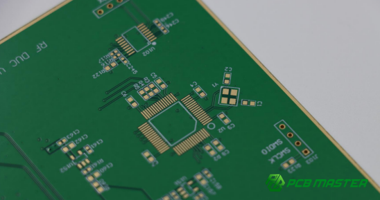
How Does PCBMASTER Provide Stable Drilling Solutions for Different FR-4 PCB Materials?
PCB drilling performance changes significantly across different FR-4 material types, such as high-frequency boards, thick copper boards, high Tg FR-4, and halogen-free FR-4. Each material has different hardness, thermal behavior, and chip removal characteristics, which directly affect hole quality and tool life. PCBMASTER provides stable PCB drilling solutions by combining material-specific process design, drill bit optimization, and strict quality control to ensure consistent results across all FR-4 categories.
What Is PCBMASTER’s Experience in Multi-Material PCB Drilling?
PCBMASTER has practical drilling experience across multiple FR-4 material types, allowing stable process control for different PCB applications.
High-Frequency PCB Drilling Experience
High-frequency FR-4 materials require smooth hole walls and low signal loss. PCBMASTER focuses on:
- Low roughness drilling control
- Stable impedance-related hole quality
- Reduced mechanical stress during drilling
This is critical for RF and high-speed digital PCBs used in communication systems.
Thick Copper PCB Drilling Experience
For thick copper boards (3oz–4oz and above), PCBMASTER controls:
- High impact force at copper entry
- Rapid tool wear
- Chip evacuation efficiency
Special drill selection and reduced stress parameters are used to prevent drill breakage.
High Tg PCB Drilling Experience
High Tg FR-4 requires stronger cutting stability due to higher hardness. PCBMASTER applies:
- Reinforced drill bits
- Controlled spindle speed
- Vibration reduction methods
This improves hole wall quality in automotive and industrial PCBs.
Halogen-Free PCB Drilling Experience
Halogen-free FR-4 is more sticky and difficult to evacuate chips. PCBMASTER improves:
- Chip removal efficiency
- Anti-smear control
- Peck drilling optimization
This reduces clogging and improves hole cleanliness.
Multi-Material Comparison Overview
| Material Type | Main Challenge | PCBMASTER Solution |
| High-Frequency FR-4 | Signal loss sensitivity | Low roughness drilling control |
| Thick Copper PCB | Drill breakage risk | Reinforced drill + slow entry control |
| High Tg FR-4 | High cutting resistance | Vibration control + optimized speed |
| Halogen-Free FR-4 | Chip sticking & smear | Improved evacuation + peck drilling |
How Does PCBMASTER Build a PCB Drilling Process Database?
PCBMASTER builds a drilling database by collecting material data, tool performance records, and standardized hole size parameters.
How Is Material Parameter Data Collected?
PCBMASTER records key parameters for each FR-4 type, including:
- Resin hardness
- Copper thickness
- Thermal behavior
- Drill wear patterns
This helps create material-specific drilling profiles for stable production.
How Are Drill Bit Matching Rules Defined?
Drill bit selection is standardized based on:
Material type (high Tg, halogen-free, etc.)
- Hole diameter
- Stack height
- Copper thickness
For example, thick copper boards require reinforced drill geometry, while high-frequency boards require smoother cutting edges.
How Are Different Hole Sizes Standardized?
Different hole diameters require different drilling strategies:
- Small holes → higher precision, faster wear control
- Large holes → lower stress, stable chip evacuation
- Deep holes → peck drilling optimization
This ensures consistent quality across all PCB designs.
How Does PCBMASTER Control PCB Drilling Yield?
PCBMASTER improves yield through real-time monitoring, sampling inspection, and strict hole quality verification.
What Is the Role of Online Inspection Systems?
Online systems monitor:
- Drill wear status
- Machine vibration
- Drilling consistency
This helps detect issues early before mass defects occur.
How Is Quality Sampling Inspection Performed?
PCBMASTER performs random sampling during production to check:
- Hole diameter accuracy
- Burr formation
- Resin smear levels
- Copper integrity
This ensures process stability throughout production batches.
What Is the Hole Wall Verification Process?
After drilling, hole walls are inspected for:
- Smoothness
- Clean copper exposure
- No delamination
- No residue contamination
This step is critical for multilayer PCB reliability before plating.
Why Do Customers Choose PCBMASTER for High-Difficulty PCB Manufacturing?
Customers choose PCBMASTER because of its stable process control, material expertise, and fast engineering response.
Why Does Material Experience Matter?
PCBMASTER understands how different FR-4 materials behave during drilling. This reduces:
- Trial-and-error time
- Production defects
- Tool breakage risk
This expertise is especially valuable for high-reliability industries like automotive and aerospace.
How Is Batch Consistency Maintained?
PCBMASTER ensures consistency through:
- Standardized drilling parameters
- Controlled tool replacement cycles
- Stable machine calibration
This guarantees that every batch meets the same quality level.
Why Is Engineering Support Important?
PCBMASTER provides fast engineering response for:
- Parameter optimization
- Drill selection advice
- Problem troubleshooting
This helps customers quickly solve production issues and improve efficiency in PCB manufacturing projects.
Conclusion
PCB drilling is a precision manufacturing process, and even small differences in material type, tool selection, or machine stability can significantly impact final PCB quality. Across different FR-4 categories—including standard FR-4, high Tg, halogen-free, high-frequency, thick copper, and ultra-thin boards—each material introduces unique challenges in cutting resistance, heat behavior, chip evacuation, and hole wall integrity.
Therefore, achieving stable drilling performance is not the result of a single adjustment, but rather the outcome of coordinated control across multiple factors, such as drill bit selection, optimized process parameters, equipment precision, and strict quality management. When these elements work together effectively, manufacturers can greatly reduce common defects like resin smear, burrs, delamination, nail heading, and drill breakage, while also improving overall yield and production efficiency.
With extensive experience across a wide range of FR-4 materials, PCBMASTER continues to provide reliable and process-stable PCB drilling solutions tailored to different application requirements. In addition, by combining engineering expertise, standardized drilling databases, and strict quality control systems, PCBMASTER ensures consistent hole quality and reliable performance in both prototype development and mass production.
Ultimately, for engineers and procurement teams, understanding these drilling fundamentals is essential. More importantly, it helps in selecting a capable manufacturing partner that can deliver high-reliability PCB products with stable and repeatable quality.
FAQs
Why Does High Tg FR-4 Wear Drill Bits Faster Than Standard FR-4?
High Tg FR-4 is more abrasive and harder than standard FR-4, which directly increases drill wear during PCB drilling.
The main reason is its higher glass transition temperature (Tg ≥ 170°C), which indicates a more rigid and heat-resistant resin system. While this improves thermal reliability in end applications, it also makes the material harder to cut. As a result, the drill experiences higher cutting resistance and faster edge wear.
In addition, high Tg FR-4 often has a denser resin structure, which increases friction during drilling. This leads to higher heat generation, accelerating tool dulling and increasing the risk of drill breakage or rough hole walls.
Therefore, PCB manufacturers typically use reinforced carbide drills, optimized cutting parameters, and stricter tool life control when processing high Tg FR-4 materials.
Why Does Halogen-Free FR-4 Produce Severe Resin Smear During Drilling?
Halogen-free FR-4 tends to generate more resin smear because its material properties make chip removal more difficult during drilling.
This type of FR-4 uses phosphorus- or nitrogen-based flame retardants instead of halogen systems. As a result, the resin becomes more elastic and slightly more adhesive under heat. During drilling, this causes chips to stick to the drill bit and the hole wall instead of being cleanly removed.
Furthermore, halogen-free materials often have lower thermal conductivity, which means heat builds up more easily around the drill zone. This softens the resin further and increases smear formation.
To reduce this issue, manufacturers typically optimize spindle speed, increase feed rate moderately, and use efficient vacuum systems combined with peck drilling strategies.
Why Is Hole Wall Roughness So Critical in High-Frequency PCBs?
Hole wall roughness is critical in high-frequency PCBs because it directly affects signal integrity and transmission loss.
At high frequencies, electrical signals travel mainly along the conductor surface due to the skin effect. Therefore, any surface irregularity on the plated via wall increases resistance and causes signal attenuation.
In addition, rough hole walls can lead to impedance instability, signal reflection, and higher insertion loss, which are especially harmful in RF, 5G, and high-speed digital circuits.
Even microscopic burrs or resin irregularities can disrupt controlled impedance structures. For this reason, high-frequency PCB drilling requires extremely smooth hole walls, low mechanical stress, and strict process control to maintain consistent electrical performance.
How Can Breakage Risk Be Reduced When Drilling Thick Copper PCBs?
Breakage risk in thick copper PCB drilling can be reduced by controlling cutting force, improving chip evacuation, and using reinforced drill tools.
Thick copper layers (3oz and above) create high impact force when the drill first contacts the copper surface. This sudden load is a major cause of drill chipping or breakage.
To reduce this risk, manufacturers use drills with stronger tip geometry (such as 135°–140° points), reinforced chisel edges, and improved flute designs for better chip removal.
In addition, drilling parameters must be carefully controlled. Lower spindle speed reduces impact force, while optimized feed rate prevents overload. In many cases, a step drilling strategy is also applied to gradually penetrate thick copper layers and reduce stress concentration.
Together, these measures significantly improve tool life and drilling stability.
How Can Hole Position Deviation Be Reduced in Thin PCB Drilling?
Hole position deviation in thin PCB drilling can be reduced by improving mechanical support, optimizing drilling parameters, and stabilizing the PCB during processing.
Thin PCBs have low rigidity, so they easily bend or shift under drilling force. This leads to positional errors and inconsistent hole alignment.
To prevent this, proper backup materials such as aluminum plates and phenolic boards are used to support the PCB and maintain flatness during drilling. Strong clamping systems, such as vacuum fixtures, are also essential to prevent movement.
In addition, high spindle speed combined with controlled feed rate helps reduce drilling force and minimize deformation. Reducing dwell time also prevents localized heat buildup, which can distort thin materials.
With proper fixture design and parameter control, manufacturers can significantly improve accuracy and consistency in ultra-thin PCB drilling.
About the Author

Carol Luo
PCB Design EngineerI'm Carol, a PCB Engineer at PCBMASTER with experience in PCB design and manufacturing engineering since 2018. I focus on translating engineering requirements into reliable PCB solutions, with expertise in stack-up design, material selection, and design-for-manufacturing (DFM). I share practical engineering insights from real-world PCB design and production experience.
Visit Carol Luo's Profile