








Circuit Board Repair Made Easy: Expert Methods for Fast Fixes
Circuit board repair is a critical part of keeping electronic devices working reliably. Small faults like broken traces, damaged components, or loose solder joints can stop a device from functioning, and knowing how to fix them quickly can save time and money. PCBMASTER, as an experienced supplier of high-quality PCBs and PCBAs , provides not only the components but also expert guidance on repair methods that are efficient and reliable. By following professional techniques, you can restore devices faster while avoiding further damage, making repairs safer and more cost-effective.
In this guide, readers will gain practical steps for diagnosing and repairing circuit boards, learn which tools are essential for efficient fixes, and discover expert tips directly from PCBMASTER. We will cover how to identify common problems, the best methods for replacing components or fixing broken traces, and strategies to prevent future issues. Whether you are a hobbyist or a technician, this article delivers clear, actionable insights to make circuit board repair straightforward, even for beginners, and helps you achieve fast, high-quality results.
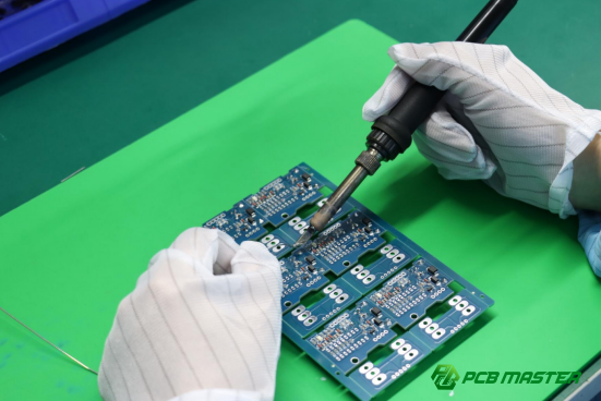
What Are the Common Issues That Require Circuit Board Repair?
Common issues include faulty components, broken traces, bad solder joints, short circuits, and overheating. Identifying these problems early is crucial for fast and effective repair.
Identifying Faulty Components on PCBs
Faulty components are often the main cause of PCB failure and can be detected through visual inspection or testing.
1. Signs of Damaged Resistors, Capacitors, ICs, and Connectors
- Resistors: Look for discoloration, burn marks, or a sudden change in resistance.
- Capacitors: Bulging tops, leaking fluids, or low capacitance indicate failure.
- ICs (Integrated Circuits): Cracks, burnt spots, or unresponsive pins are common signs.
- Connectors: Bent pins, corrosion, or loose contacts can disrupt circuits.
2. Examples of Heat Damage, Corrosion, or Mechanical Stress
- Overheated components may appear blackened or charred.
- Corrosion often shows as a white powdery residue, especially in humid environments.
- Mechanical stress, such as bending or dropping, can crack solder joints or break leads.
Practical Example: In a home router repair, a burned capacitor can prevent power-up. Detecting the bulge visually and measuring capacitance confirms the problem.
Diagnosing Broken Traces and Solder Joints
Broken traces and cracked solder joints interrupt the electrical flow. Diagnosing them requires careful inspection and testing.
1. Methods to Locate Open Circuits and Cracked Solder Joints
- Use a multimeter in continuity mode to check if current flows along traces.
- Inspect solder joints under magnification to spot cracks or gaps.
- Tap lightly on suspicious components while testing; intermittent connections can reveal hidden breaks.
2. Tools Recommended by PCBMASTER for Diagnosis
- Multimeter: For voltage, resistance, and continuity testing.
- Magnifying glass or microscope: Essential for high-density boards.
- Thermal imaging camera: Detects hotspots that indicate faulty components or broken traces.
Practical Example: PCBMASTER technicians often use a thermal camera to quickly find a trace break on a power supply board, reducing troubleshooting time.
Recognizing Signs of Short Circuits and Overheating
Shorts and overheating can damage the entire PCB if left untreated. Recognizing early symptoms helps prevent further failures.
1. Symptoms of Shorts in Consumer Electronics and Industrial Boards
- Unexpected shutdowns, smoke, or burning smell.
- Flickering lights or devices drawing excessive current.
- Tripped fuses or blown protection circuits.
2. How Expert Repair Methods Prevent Further Damage
- Isolating faulty areas before powering the board.
- Using controlled heat methods to replace damaged components.
- Testing with low voltage first to ensure the repair is effective.
Practical Example: In an industrial motor controller, a shorted MOSFET caused repeated fuse failures. PCBMASTER experts isolated the short and replaced the faulty MOSFET, restoring safe operation.
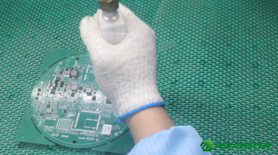
How Can You Prepare for Efficient Circuit Board Repair?
Preparing properly is essential for fast, safe, and successful circuit board repair. This involves gathering the right tools, creating a safe workspace, and understanding the PCB layout before starting.
Gathering the Right Tools and Equipment
Having the proper tools ensures repairs are precise and reduces the risk of damaging the board.
1. Essential Tools
- Soldering station: Provides consistent heat for removing and attaching components.
- Flux: Helps solder flow smoothly and prevents oxidation.
- Desoldering pump: Quickly removes excess solder or damaged components.
- Precision tweezers: Allows careful handling of small components without bending or breaking them.
2. Optional Professional Tools
- Hot air rework station: Ideal for removing surface-mounted devices (SMDs) efficiently.
- Microscope or magnifier: Helps inspect small solder joints and identify micro-cracks.
Practical Example: PCBMASTER technicians often use a microscope to locate tiny cracks in smartphone PCBs, which are invisible to the naked eye but can cause intermittent failures.
Ensuring a Safe and Controlled Repair Environment
Safety and environment control prevent accidental damage to the PCB and ensure consistent repair quality.
1. Anti-Static Precautions
- Use ESD mats and wrist straps to prevent static electricity from damaging sensitive components.
- Avoid synthetic clothing or surfaces that generate static.
2. Temperature Control and Workspace Cleanliness
- Maintain moderate room temperature to prevent overheating during soldering.
- Keep the workspace tidy, free from dust or conductive debris that could short circuits.
Practical Example: In industrial PCB repair, a dusty workspace caused repeated short circuits.After installing anti-static mats and improving cleanliness, repair efficiency improved significantly.
Understanding the PCB Layout Before Repairing
Knowing the board layout reduces mistakes, speeds up repairs, and ensures correct component replacement.
1. Reading Schematics and Identifying Component Placements
- Study the circuit diagram to locate critical components and understand signal flow.
- Recognize test points for easier troubleshooting.
2. PCBMASTER Tips for Documentation and Labeling
- Label components removed during repair to avoid confusion during reassembly.
- Take photos or notes to document connections and orientations.
Practical Example: For a multi-layered PCB , PCBMASTER recommends labeling pins on a disconnected microcontroller. This prevents miswiring when reinstalling the component, saving time and avoiding damage.
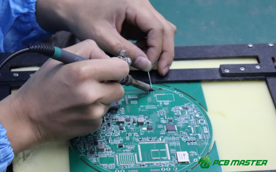
What Are the Step-by-Step Methods to Repair Circuit Boards Quickly?
Efficient circuit board repair follows a structured sequence: cleaning, fixing solder joints, replacing faulty components, repairing broken traces, and testing the board. Each step minimizes errors and speeds up the repair process.
Cleaning and Preparing the PCB Surface
A clean PCB surface ensures better soldering and reduces the risk of shorts or poor connections.
1. Removing Dust, Oxidation, and Flux Residues
- Use soft brushes or compressed air to remove dust.
- Oxidized areas can be cleaned gently with a fine abrasive pad or chemical solution.
- Residual flux should be wiped using isopropyl alcohol (IPA) or other electronics-safe cleaners.
2. Example of Chemical Cleaners Safe for Electronics
- Isopropyl alcohol (90%+): Evaporates quickly, leaving no residue.
- Flux removers: Specially formulated for PCBs to clean soldering residues.
Practical Example: PCBMASTER technicians cleaned a dusty LED controller board with IPA before soldering new components, preventing cold solder joints.
Fixing Damaged Solder Joints
Repairing solder joints restores electrical continuity and prevents intermittent failures.
1. Reflowing vs. Resoldering: When to Use Each Method
| Method | Description | When to Use | Advantages |
| Reflowing | Heat the existing solder to reconnect a loose joint. | Minor cracks or slightly loose solder joints. | Quick, preserves existing solder, minimal disturbance to components. |
| Resoldering | Remove old solder completely and apply new solder to the joint. | Severely damaged, contaminated, or oxidized joints. | Ensures strong, clean connection; prevents future failures. |
2. Step-by-Step Soldering Guidance from PCBMASTER
- Heat the joint with a soldering iron for 2–3 seconds.
- Apply flux to improve solder flow.
- Add a small amount of fresh solder and remove the iron.
- Inspect under magnification to ensure smooth, shiny joints.
Practical Example: On a motherboard repair, reflowing a cracked capacitor joint restored stability without removing the component, saving time.
Replacing Faulty Components Efficiently
Replacing components must be precise to avoid damaging the PCB.
1. How to Remove Damaged ICs, Resistors, and Capacitors Without Harming the PCB
- Use a desoldering pump or solder wick to remove solder.
- Lift components gently with tweezers once solder is melted.
- For ICs, use a hot air station to evenly heat pins and prevent board warping.
2. Recommended Replacement Sourcing Tips
- Use high-quality components from trusted suppliers.
- PCBMASTER recommends checking part numbers carefully and comparing datasheets.
Practical Example: A burned-out voltage regulator on a power supply board was replaced using proper desoldering and sourcing, restoring full function within 20 minutes.
Repairing Broken Traces and Circuit Paths
Broken traces interrupt current flow; repairing them restores connectivity.
1. Methods: Wire Jumpers, Conductive Ink, or Copper Tape
- Wire jumpers: Solder a thin insulated wire to reconnect separated points.
- Conductive ink: Apply to small breaks in traces for low-current circuits.
- Copper tape: Best for larger or high-current traces on multi-layer boards.
2. Illustrative Examples for High-Density Boards
- On a smartphone PCB, PCBMASTER engineers used fine wire jumpers under a microscope to repair tiny broken traces without removing surrounding components.
Testing and Verification After Repair
Testing ensures the repair is successful and prevents future issues.
1. Functional Testing Using Multimeter and Power-Up Checks
- Measure voltage at critical points.
- Check continuity to confirm repaired traces.
- Power the device at low voltage first to verify safety.
2. PCBMASTER Advice on Iterative Verification to Avoid Repeat Repairs
- Test each repair step before moving to the next.
- Document test results for future reference.
Practical Example: After replacing a faulty microcontroller, PCBMASTER tested all input/output pins individually, preventing a second round of repairs due to missed errors.
Which Expert Tips Can Reduce Circuit Board Repair Time?
Efficient workflow, proper thermal management, access to expert resources, and preventive measures can significantly reduce the time spent on circuit board repair while maintaining quality.
Organizing Components and Tools for Workflow Efficiency
Keeping components and tools well-organized saves time and prevents mistakes during repair.
- Component Trays and Labeling: Sort and label all components before starting repairs. Use small trays or bins for resistors, capacitors, ICs, and screws.
- Pre-Sorting Strategies: Arrange components in the order of repair steps to avoid searching during work. Keep frequently used tools like soldering irons, tweezers, and multimeters within easy reach.
Practical Example: PCBMASTER engineers prepare a labeled tray for a smartphone motherboard repair, reducing the time spent finding tiny SMD components from 10 minutes to under 2 minutes.
Using Thermal Management Techniques During Repair
Controlling heat during soldering prevents damage and speeds up repair.
- Heat Sinks: Attach heat sinks to sensitive components when applying high temperatures to avoid overheating.
- Temperature-Controlled Soldering: Use soldering irons with adjustable temperature settings to apply just enough heat.
- Avoiding Heat Damage: Always heat only the target joint, not the entire board, to protect surrounding components.
Practical Example: When repairing a high-density PCB, PCBMASTER technicians use a temperature-controlled soldering station and a clip-on heat sink, preventing warping of adjacent ICs.
Leveraging PCBMASTER’s Technical Support and Resources
Using expert resources speeds troubleshooting and ensures accurate repairs.
- Repair Guides and Datasheets: Refer to official datasheets for correct pinouts, voltage limits, and component specs.
- Consultation Services: PCBMASTER offers support to clarify complex repair issues, avoiding trial-and-error approaches.
- Reference Examples: Follow PCBMASTER step-by-step guides for similar boards to replicate proven repair strategies.
Practical Example: A technician repairing a multi-layer power supply consults PCBMASTER’s datasheet and saves hours identifying the correct voltage test points.
Preventive Measures to Minimize Future Repairs
Preventive practices reduce the likelihood of recurring failures and save repair time in the long run.
- Proper PCB Handling: Avoid bending or touching sensitive components unnecessarily.
- Protective Coatings: Apply conformal coating to prevent moisture and dust damage.
- Design Considerations: Ensure components are spaced correctly and that heat-generating parts have adequate dissipation.
Practical Example: In an industrial controller board, PCBMASTER recommended applying conformal coating, which prevented corrosion and reduced repeat repair requests by 60%.
What Are the Cost-Effective Ways to Repair Circuit Boards Without Compromising Quality?
Cost-effective circuit board repair balances quality and expense by choosing the right repairs, sourcing reliable components, and optimizing workflow. This ensures durable repairs without overspending.
Identifying Which Repairs Can Be Done In-House vs. Professional Help
Not all PCB repairs are suitable for DIY; understanding what can be done in-house saves money and prevents mistakes.
- Cost-Benefit of DIY Repair: Simple repairs like replacing small resistors or cleaning solder joints can be done in-house with basic tools. This saves money but requires careful attention to avoid damage.
- Outsourcing to PCBMASTER-Certified Technicians: Complex issues such as multi-layer PCB faults, microcontroller replacement, or high-current traces should be handled by experts. Outsourcing avoids repeat repairs and protects expensive boards.
Practical Example: A home electronics enthusiast replaced a burnt LED resistor successfully in-house, but when a microprocessor IC failed, PCBMASTER’s certified repair service restored the board in one session, avoiding costly trial-and-error.
Choosing High-Quality Replacement Components
Using reliable components prevents future failures and ensures cost-effectiveness over time.
- Avoiding Counterfeit Parts: Low-cost counterfeit components may fail quickly and damage other parts. Always check datasheets and verify suppliers.
- Sourcing from Trusted Suppliers Like PCBMASTER: Trusted suppliers guarantee authentic, high-quality components with proper specifications, ensuring repairs last longer and reducing repeat expenses.
Practical Example: A power supply board failed twice after using cheap capacitors. Switching to genuine PCBMASTER capacitors eliminated repeat failures and saved repair costs in the long run.
Efficient Workflow Techniques to Save Time and Resources
Organized repair methods reduce wasted time, minimize errors, and cut overall repair costs.
- Batch Repairs: Repair multiple boards of the same type together, maximizing tool usage and efficiency.
- Modular Replacement: Replace faulty modules rather than individual components when feasible, saving inspection and troubleshooting time.
- Minimizing Component Wastage: Plan repairs, use proper handling, and store unused parts safely to reduce losses.
Practical Example: PCBMASTER repaired a batch of 20 identical motor controller boards using modular replacement. This reduced total labor time by 40% and minimized part wastage.
Conclusion
Efficient circuit board repair starts with careful preparation, including gathering the right tools, organizing components, and understanding the PCB layout. Accurate diagnosis is essential to identify faulty components, broken traces, and signs of short circuits or overheating, which allows targeted and effective repairs. Following step-by-step repair methods, such as cleaning the board, fixing solder joints, replacing faulty components, and repairing broken traces, ensures both speed and reliability. Applying expert tips, including thermal management, workflow optimization, and leveraging trusted resources, further reduces repair time and minimizes errors.
PCBMASTER plays a vital role in supporting successful repairs by providing high-quality components, detailed datasheets, repair guides, and technical consultation. Using authentic parts and following PCBMASTER’s expert recommendations prevents repeat failures and improves the overall durability of repaired boards. By combining practical repair strategies with expert guidance, users can achieve professional-level results without unnecessary trial and error.
Ultimately, following these best practices ensures safe, fast, and cost-effective circuit board repair. Whether performing minor in-house fixes or consulting PCBMASTER-certified technicians for complex issues, adhering to a structured approach maximizes efficiency while protecting sensitive electronics. Implementing these methods consistently will save time, reduce costs, and maintain the performance and longevity of your PCBs.
FAQs
1. How can I tell if my circuit board is worth repairing or needs replacement?
A circuit board is usually worth repairing if the damage is limited to a few components, broken solder joints, or minor trace issues. Replacement is recommended when there are extensive burnt areas, multiple short circuits, or critical microcontroller damage. Checking the cost of components and labor versus the value of a new board helps make this decision. For high-value or complex boards, consulting PCBMASTER-certified technicians ensures a safe and cost-effective choice.
2. What is the safest way to desolder components without damaging the PCB?
Use a temperature-controlled soldering iron and a desoldering pump or wick to remove solder gradually. For sensitive components, a hot air rework station distributes heat evenly, reducing the risk of lifting pads or traces. Always handle the PCB with anti-static precautions and avoid applying excessive force on the component. Applying flux helps solder flow smoothly and minimizes thermal stress.
3. Can small cracks in PCB traces be reliably repaired at home?
Yes, small cracks can be repaired using wire jumpers, conductive ink, or copper tape, depending on the trace size and current. Using a magnifier ensures precise placement. However, for high-density or multilayer boards, professional repair by PCBMASTER is recommended, as improper repair may cause intermittent failures.
4. How often should I perform preventive maintenance on circuit boards?
Preventive maintenance should be done every 6–12 months for consumer electronics and more frequently for industrial boards exposed to heat, dust, or moisture. Maintenance includes cleaning dust, inspecting solder joints, checking connectors, and testing for early signs of component wear. Regular maintenance helps avoid costly repairs and extends PCB lifespan.
5. Are there specialized tools recommended by PCBMASTER for high-density PCB repair?
Yes, PCBMASTER recommends tools such as microscopes or magnifiers, hot air rework stations, temperature-controlled soldering irons, and precision tweezers for high-density PCB repair. These tools allow accurate work on tiny components and closely spaced traces, reducing repair errors and preventing damage to surrounding parts.
About the Author

Carol Luo
PCB Design EngineerI'm Carol, a PCB Engineer at PCBMASTER with experience in PCB design and manufacturing engineering since 2018. I focus on translating engineering requirements into reliable PCB solutions, with expertise in stack-up design, material selection, and design-for-manufacturing (DFM). I share practical engineering insights from real-world PCB design and production experience.
Visit Carol Luo's Profile

