


Metal Core PCB Ultimate Guide for Efficient Thermal Management
Understanding Metal Core PCBs
**·**Metal core boards are designed for efficient heat management and incorporate a metal base for effective heat management.
**·**Metal Core PCBs use a metal base layer, often aluminum or copper, instead of traditional fiberglass, enhancing thermal management.
**·**The basic structure of metal core PCBs includes a metal plate, metal copper foil, and thermal insulating layers. The metal plate provides structural support and thermal conductivity.
**·**A typical metal core PCB is made up of the solder mask layer, circuit layer, copper layer, dielectric layer, and metal core layer (also referred to as the metallic core).
**·**The main purpose of the metal in metal core PCBs is to transfer heat from critical board components to less crucial areas, helping to manage thermal performance.
**·**Metal core PCBs divert heat away from critical components, effectively managing temperature and preventing overheating.
**·**Using metal core printed circuit boards (a type of printed circuit board) is a method to address heat dissipation issues in high-power applications.
**·**Metal core PCBs are commonly used in LED lighting applications for their excellent heat dissipation properties, which extend the lifespan of the LEDs.
Key Applications of Metal Core PCBs
· Metal core PCBs are most widely used in LED lighting technologies due to their effective thermal management, and are widely found in LED lighting systems where reliable performance is critical.
· Key applications of metal core PCBs include audio equipment, power regulators, and sensor systems, which all benefit from their effective heat dissipation capabilities.
· Metal core PCBs are essential in applications requiring effective heat management, such as residential, industrial, and automotive lighting, especially for high power LEDs that demand superior thermal performance.
LED Lighting Solutions
**·**Metal core PCBs help solve heat dissipation issues encountered in high-power LED applications.
**·**Single-layer metal core PCBs with an aluminum substrate help keep heat generating components cooler, providing the lowest operating temperature and maximum brightness for LED lighting.
**·**Aluminum MCPCBs are favored for their balance of thermal performance and cost efficiency in various LED applications.
**·**Aluminum has excellent heat dissipation properties and is lightweight, making it ideal for LED applications.
**·**Aluminum is considered the most economical choice for metal core PCBs, ensuring cost-effectiveness in production.
**·**Single-layer metal core PCBs are utilized in various applications including LED lighting, automotive relays, and audio devices.
Power Supplies and High-Power Electronics
**·**Metal core PCBs are increasingly utilized in power supplies and high-power electronics due to their superior thermal management capabilities, effectively removing heat to maintain optimal performance.
**·**Copper MCPCBs are preferred for automotive lighting as they effectively handle the high thermal loads from power-intensive applications.
**·**Effective thermal management in power supplies ensures improved performance and extends the lifespan of high-power electronic devices.
Types of Metal Core PCBs
Board MCPCBs can be manufactured with single, two, or multiple layers depending on application requirements.
**·**Single-sided metal core PCBs are known for their simplicity and cost-effectiveness, making them suitable for a range of less complex electronic designs.
**·**Double-sided metal core PCBs, often referred to as two-layer designs, allow for more complex design layouts, enabling higher component density and better thermal performance.
**·**Multi-layer metal core PCBs can include multiple layers and sometimes two layers of copper, providing enhanced thermal management and are ideal for advanced electronic systems requiring intricate circuit configurations.
Single-Sided Metal Core PCBs
·Single-sided metal core PCBs consist of a single conductive copper layer atop a dielectric layer and a metal substrate for thermal management.
·The structure typically includes a single copper layer above a dielectric layer.
·Aluminum is often used for single-sided metal core PCBs due to its lightweight nature and effective thermal conductivity.
·Common materials used in single-sided metal core PCBs include aluminum and copper.
·Aluminum-based MCPCBs are widely utilized in residential LED bulbs due to their cost-effectiveness and efficient heat management.
Double-Sided Metal Core PCBs
**·**Double-sided metal core PCBs feature conductive layers on both sides, often utilizing two copper layers for improved circuit complexity and performance.
**·**These PCBs use plated through holes to connect layers, enabling both surface mount and through-hole components to be placed on either side.
**·**In double-sided metal core PCBs, the antipad serves to indicate the areas of via holes that need insulation.
**·**Copper MCPCBs are utilized for high-performance needs due to their superior thermal and electrical conductivity.
Multi-Layer Metal Core PCBs
·Multi-layer metal core PCBs consist of several conductive layers separated by thermal dielectric material, enhancing their heat dissipation capabilities.
·In multi-layer configurations, SMT components are generally limited to one side, while internal layers can accommodate advanced routing techniques.
Material Choices for Metal Core PCBs
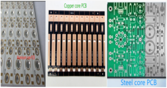
**·**The common metals used in manufacturing metal core PCBs include aluminum, copper, and steel alloys. The choice of metal material (such as aluminum, copper, or steel alloys) is crucial for both thermal and electrical performance.
**·**Metal core PCBs typically utilize a metal layer, often aluminum, as a core component to enhance thermal conductivity. These metal substrates provide advantages such as superior heat dissipation and increased durability.
**·**The manufacturing process begins with selecting appropriate materials, followed by layering and bonding techniques.
**·**The selection of suitable core material, typically aluminum or copper, significantly influences thermal performance of metal core PCBs.
**·**Aluminum-based metal core PCBs are non toxic and environmentally friendly compared to traditional PCB materials, making them a safer and more sustainable choice.
Aluminum Core PCBs
**·**The thermal conductivity of aluminum PCBs is approximately 200 W/mK, which is substantially higher than standard FR4 materials.
**·**Aluminum cores generally provide a thermal conductivity around 237 W/m·K, while copper cores can reach approximately 398 W/m·K.
**·**Materials typically used for the metal core in double-layer MCPCBs include aluminum or copper.
**·**For single-sided LED MCPCBs, materials can include Aluminum 5052, Aluminum 6061, or Copper C1100.
**·**The typical thickness range for aluminum cores in metal core PCBs is 40 to 120 mils, commonly 40 to 60 mils.
**·**Aluminum circuit boards can withstand temperatures up to 400 °C.
**·**Immersion silver is also a common surface finish option for aluminum core PCBs, providing enhanced surface protection.
Copper Core PCBs
**·**Copper core PCBs are favored for their outstanding thermal performance, especially in high-demand applications, offering better performance in heat dissipation compared to aluminum core options.
**·**The benefits of copper core PCBs enhance their use in applications that require efficient heat dissipation.
**·**A disadvantage of using copper in single-sided metal core PCBs is their higher cost compared to other materials.
**·**Thermally conductive prepreg plays a crucial role in facilitating electric insulation and heat transfer between the copper and metal layer.
**·**Higher thermal conductivity of the prepreg significantly improves heat transfer in copper core PCBs.
Steel Alloy Core PCBs
·Steel alloy core PCBs offer superior strength and durability compared to other materials, making them ideal for heavy-duty applications.
·The strength of steel alloys allows them to withstand higher mechanical stress, ensuring long-term reliability in demanding environments.
·Applications in industries such as automotive and aerospace often require the enhanced strength that steel alloy core PCBs provide.
·Manufacturing steel alloy core PCBs may involve specialized processing techniques to accommodate the unique properties of steel.
Manufacturing Process of Metal Core PCBs
**·**The mcpcb manufacturing process includes specialized steps like material selection, layer bonding, drilling, and final assembly to ensure effective heat dissipation and structural integrity.
**·**Metal core PCBs are made by bonding copper with a thermally conductive dielectric layer, which is then attached to the metal base. The standard process for PCB fabrication, often used with FR4 laminates, is adapted for metal core PCBs by adding steps such as additional drilling and insulation to accommodate layer transitions without short circuits.
**·**Copper foil is typically adhered to the dielectric material before bonding it to the metal substrate.
**·**The arrangement of layers in a metal core PCB stackup is crucial for effective routing and component placement. The design process for metal core PCBs must consider factors like minimizing plated through holes and ensuring proper lamination for optimal performance.
Bonding Layers
**·**The bonding process in metal core PCBs generally begins with the copper foil being bonded to a layer of thermally conductive dielectric material, which is often a dielectric polymer layer designed for high thermal conductivity.
**·**In a single-sided LED MCPCB, a layer of thermally conductive dielectric material is typically bonded to the metal layer.
**·**For a one-layer MCPCB, the electroless plating process is bypassed after the drilling process.
Plated Through Holes and SMT Components
**·**Minimize use of plated through-hole components, as this is a major factor in optimizing MCPCB design and maintaining performance in metal core PCBs.
**·**Antipads are essential in double-sided metal core PCBs as they indicate the via-hole region that needs insulating filter.
Ensuring Symmetrical Stack-Up
·In metal core PCBs, the stack-up refers to the arrangement of layers, including the metal core and dielectric materials.
·Maintaining symmetry in the stack-up of multilayer metal core PCBs is crucial to prevent warpage issues.
·If the stack-up is not symmetrical, it can lead to mechanical stresses that cause the PCB to warp during manufacturing or operation.
Thermal Management in Metal Core PCBs
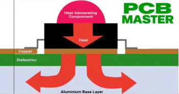
**·**The metal layer in MCPCBs functions as a heat sink and can also serve as a heat spreader in certain designs, effectively dissipating the heat produced by components like LEDs.
**·**Metal core PCBs are engineered to draw heat away from components and help dissipate heat generated by electronic components, enhancing performance and reliability.
**·**Excellent heat conduction in metal core PCBs directs heat to heat sink areas, and conductive cooling is achieved by transferring heat directly from components to the metal core.
**·**The incorporation of metal cores into PCBs allows for reduced thermal resistance, and the use of a dielectric polymer layer with high thermal conductivity results in lower thermal resistance, promoting quicker heat dissipation.
**·**Effective thermal management in PCBs is crucial for reliability with high power and high component density.
**·**To prevent total loss of system functionality, it is essential to manage heat generation and dissipation effectively.
**·**Heat is easily dissipated in metal core PCBs, allowing critical components to function without issues.
**·**Metal core PCBs can help manage heat generation in power supplies, making them suitable for high-efficiency applications.
**·**Thermal issues, such as starved thermals, can hinder effective heat transfer and lead to overheating.
**·**Properly implemented plated through-holes enhance the mechanical strength and thermal dissipation in PCBs.
Heat Sinks vs. Heat Spreaders
**·**Heat sinks and heat spreaders both serve the purpose of dissipating heat from heat-generating components to the surrounding air. In metal core PCBs (MCPCBs), a metal heatsink backing is often integrated to enhance heat dissipation and improve thermal management.
**·**Heat sinks maximize surface area and airflow to effectively dissipate heat.
**·**There are two types of heat sinks: passive heat sinks, which rely on natural convection, and active heat sinks, which use fans or mechanisms to assist in airflow.
**·**Heat spreaders work by distributing heat evenly across a larger area, facilitating more efficient cooling.
**·**Heat spreaders are ideal for applications under extreme shock and vibration, as well as in sealed systems where efficient thermal management is crucial.
Thermally Conductive Dielectric Materials
**·**Thermally conductive dielectric materials are essential for effective heat transfer in MCPCBs, and dielectric thickness is a key parameter influencing both heat transfer and electrical insulation.
**·**Higher thermal conductivity in dielectric materials allows for better heat transfer efficiency in metal core PCBs.
**·**The insulating layer applied to the metal core is essential for electrical isolation while allowing thermal transfer.
**·**Thermally conductive dielectrics are crucial for ensuring electrical insulation while also facilitating heat flow.
**·**Metal core PCBs can be designed to enhance heat transfer efficiency by integrating a dielectric layer with high thermal conductivity.
**·**In MCPCBs, thermal vias can significantly improve heat transfer from LEDs to the metal core.
Design Guidelines for Metal Core PCBs
·Access to the right design tools and a complete library of stackup materials is necessary for designing a multilayer metal core PCB.
·Metal core PCB design guidelines differ from conventional FR4 design guidelines, requiring specific considerations.
·Design flaws can arise from improper component placement or material selection, negatively impacting metal core PCB performance.
·Designing effective ground planes is essential to minimize electromagnetic interference (EMI) in metal core PCBs.
·Altium Designer provides access to a complete suite of design tools, integrating all necessary functions into one platform.
·Altium Designer includes features for schematic capture, ultra-accurate CAD features, and a complete routing suite.
·Using surface mount technology components allows for a more streamlined design in metal core PCBs.
·Metal core PCBs are preferred in high switching power applications due to their efficient thermal performance.
·After defining dielectric layers in PCB design, it is crucial to begin placing components and routing traces to avoid potential issues.
Component Selection
·Selecting appropriate components is crucial for optimizing performance in metal core PCBs.
·Surface-mount components are preferred in metal core PCBs due to their efficiency and ease of assembly.
·Single-sided metal core PCBs can accommodate surface mount components effectively.
·Designers must ensure that solder does not wick through to the backside when using through-hole components.
Grounding Techniques
·Grounding techniques in metal core PCBs are critical for preventing issues such as ground loops, especially in high-frequency applications.
·Grounding of metal core PCB planes is essential to prevent ground loops in high-frequency applications.
·Ground planes in metal core PCBs can enhance plane capacitance, which is beneficial for signal integrity.
·Proper grounding techniques help maintain low surface temperatures in metal core PCBs, ensuring efficient thermal management.
Advantages of Metal Core PCBs over Traditional PCBs
·Metal core PCBs have improved heat dissipation capabilities, transferring heat 8 to 9 times faster than traditional FR4 PCBs.
·The replacement of ceramics and fiberglass with metal cores enhances the durability of metal core PCBs.
·Metal core PCBs utilize thermally conductive dielectric materials that enhance thermal management.
·Metal core PCBs offer greater structural integrity and are less prone to thermal-induced distortions compared to traditional PCBs.
Common Challenges and Solutions in Metal Core PCB Design
·Acid traps, caused by acute angles in circuit designs, can lead to material degradation during the etching process.
·Interconnect defects can occur during drilling processes and can compromise the electrical connectivity of multi-layer PCBs.
·Insufficient copper-to-edge clearance can expose copper layers to corrosion and short-circuiting risks if not properly managed.
·Through-hole components can be utilized, but care must be taken to prevent solder from wicking through to the opposite side.
·These boards effectively minimize vibration issues, preventing component dislodgment.
·Ionic contamination from residues can lead to electrochemical issues, affecting the performance and reliability of PCBs.
FAQs
Q. What is a metal core PCB? What is the fundamental difference from traditional PCBs?
A. A metal core PCB is a special type of circuit board that uses metal (such as aluminum or copper) as its base. Its structure includes a metal core layer, a thermal insulation layer, a copper circuit layer, etc., with the core function of efficient heat dissipation.
The fundamental differences from traditional FR4 PCBs are:
Base material: Metal replaces fiberglass, increasing thermal conductivity by 8-9 times (e.g., aluminum core ≈237 W/m·K, FR4 only 0.2-0.3 W/m·K);
Thermal management capability: Directly conducts component heat to the metal base, avoiding performance degradation or shortened lifespan caused by insufficient heat dissipation in traditional PCBs.
Q. What metal materials are commonly used in metal core PCBs? What scenarios are they suitable for?
A. Common materials and applicable scenarios are as follows:
Aluminum: Low cost (≈1/3 of copper), lightweight, thermal conductivity ≈237 W/m·K. Suitable for mid-to-low power applications like LED lighting (e.g., household bulbs, streetlights) and consumer electronics;
Copper: High thermal conductivity (398 W/m·K), but expensive and heavy. Suitable for high-power equipment (e.g., automotive inverters, 5G base station power amplifiers);
Steel alloys: High strength, resistant to mechanical stress, lower thermal conductivity (20-30 W/m·K). Primarily used in scenarios requiring extreme structural stability like automotive engine bays and aerospace.
Q. Is the production cycle for metal core PCBs longer than traditional PCBs? Why?
A. Yes, typically 50%-100% longer. Traditional FR4 PCB production takes 3-5 days, while aluminum-based PCBs require 7-8 days, and copper-based ones take 10 days.
Key reasons: Metal bases require special pretreatment (e.g., oxidation prevention); the lamination process for thermal insulation layers is complex (requiring precise temperature and pressure control to balance insulation and thermal conductivity); and copper-based material processing causes greater equipment wear, reducing drilling and cutting efficiency.
Q. What issues require special attention when designing metal core PCBs?
A. Material matching: Select the metal base according to power requirements (e.g., aluminum base for LEDs >100W, copper base for >500W);
Thermal design: Add thermal vias (diameter 0.4-0.6mm) to connect components to the metal core, or design heat sinks on the back;
Process limitations: Avoid excessive through-hole components (to prevent solder penetration and short circuits), prioritize Surface Mount Technology (SMT);
Symmetry control: Multilayer designs must ensure symmetrical stacking to reduce warpage risk under high temperatures.
Why choose PCBMASTER: https://www.pcbmaster.com/why
Join us: https://www.pcbmaster.com/login

