


Core Applications of Aluminum Substrates Technical Parameters and Product Design Guide
Ⅰ. Technical Characteristics of Aluminum Substrates

Aluminum substrates (Metal Core PCBs) feature a sandwich structure: conductive layer (copper foil), insulation layer (thermally conductive dielectric material), and metal baseplate (aluminum alloy). Their core advantages are reflected in three technical parameters:
1.Thermal Conductivity Breakthrough
Traditional FR-4 substrates: 0.3 W/m·K
Aluminum substrates:
①Modified epoxy dielectric layer: 1.5–3.0 W/m·K
②Ceramic-filled dielectric layer: Up to 8.0 W/m·K
Measured thermal resistance reduced by 60–80% compared to standard PCBs
2.Mechanical Strength Comparison
①5083 aluminum alloy baseplate: Tensile strength 270 MPa (8× FR-4’s 35 MPa)
②Vibration test (20G acceleration, 20–2000 Hz): Failure rate reduced by 92%
Voltage Resistance
①UL-certified dielectric layer: Withstands 4 kV/mm breakdown voltage
②Passes 3000V AC/1min withstand voltage test for EV high-voltage components
Ⅱ. Technical Solutions for Key Applications
2.1 High-Density LED Lighting Systems

Osram 150W LED Streetlight Module Test Data:
①Junction temperature reduced from 102°C to 68°C (1.5mm Al substrate)
②Luminous efficacy increased by 18% (130 lm/W → 153 lm/W)
③Lifespan extended from 3,000 to 10,000 hours (85°C/85% RH)
Critical Design Parameters:
①Copper thickness ≥ 2 oz (70 μm)
②Thermal via diameter: 0.3 mm, spacing: 1.2 mm
③Thermal resistance difference ≤15% between soldering/non-soldering zones
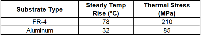
2.2 EV Power Modules

Tesla Model 3 Motor Controller Solution:
①Substrate dimensions: 220 mm × 150 mm × 2.0 mm
②Continuous current: 200A (400A peak)
③Passed 3,000 cycles (-40°C ↔ +150°C)
Thermal Simulation Comparison:
2.3 Industrial Power Supplies

3kW Telecom Power Supply Test Results:
①Volume reduced by 40% with Al substrate
②Efficiency improved from 92.1% to 94.4%
③Full-load temperature dropped from 95°C to 61°C
Layout Specifications:
①Power device spacing ≥3 mm
②Ground copper coverage ≥70%
③5 mm non-metal edge margin
Ⅲ. Key Design Parameters Reference

Ⅳ. Technology Trends
1.Composite Substrates: Mitsubishi’s Al-SiC substrate (220 W/m·K) deployed in 5G base station PAs
2.Direct Plating: 400 μm copper thickness, 300% current capacity improvement
3.3D Structures: Toyota’s patented wave-shaped substrate (+70%散热面积)
Market Data:
①2023 global Al substrate market: $1.87B (QYR)
②EV sector CAGR: 31.2% (2022–2027 forecast)
Ⅴ. Design Validation Protocol
①Thermal cycling: ≥500 cycles (-55°C ↔ +125°C)
②Insulation reliability: 1,000h @85°C/85% RH
③Mechanical vibration: 10–2000Hz random, PSD 0.04g²/Hz
Military Project Case:
①Vibration: 20G peak, 1h per axis
②Failed components: 17 (FR-4) → 2 (Al substrate)
③Temp rise rate: 3.2°C/min → 1.1°C/min
Data Sources:
1.IPC-2223B Metal Base Design Standard
2.IEEE Trans. Power Electronics Vol.37
3.CECA 2023 Annual Report
This technical analysis demonstrates aluminum substrates’ unparalleled advantages in thermal management and structural reliability. With the rise of wide-bandgap semiconductors, metal-core PCB technology is evolving toward higher integration and lower thermal resistance. Engineers should prioritize aluminum substrates for power modules, automotive electronics, and other high-stress applications.
Aluminum Substrate Market Outlook Technology-Driven Evolution in the Next Decade
Aluminum PCB Engineering Practical Guide From Material Properties to Design Pitfalls
Author: Jack Wang

