






Types of PCBs Used in Electric Vehicles: Applications by EV System
The automotive industry is being forced by electric vehicles (EVs) to move away from mechanically driven platforms to highly integrated electronic systems. EV has advanced electronic systems including battery management systems (BMS), motor controllers, power inverters, on-board chargers, advanced driver-assistance systems (ADAS) as compared to traditional internal combustion engine vehicles. At the heart of these systems are printed circuit boards (PCBs ). These are the necessary platform to integrate components, distribute power and transmit signals for the operation of modern vehicles. As vehicle electrification and intelligence continue to develop steadily, the market demand for automotive PCBs with high reliability and high performance is gradually increasing.
The different electrical, thermal and mechanical requirements of these systems mean that specific PCB technologies are needed in different sections of an EV to achieve optimal performance and reliability.
So, what specific PCB technologies are utilized in key EV systems, and why? We discuss these technologies in detail in this article.
Quick Overview: PCB Types Used Across EV Systems
| EV System | Common PCB Types | Primary Design Requirements |
|---|---|---|
| Battery Management System (BMS) | Heavy Copper PCB , FR-4 PCB , HDI PCB | High current capacity, thermal management, compact integration |
| Inverter & Motor Controller | Heavy Copper PCB, Ceramic PCB , IMS PCB | High power handling, electrical insulation, heat dissipation |
| On-Board Charger (OBC) & DC/DC Converter | Heavy Copper PCB, Metal Core PCB | Efficient power conversion, thermal stability |
| ADAS | HDI PCB, High-Speed PCB , High-Frequency PCB | High-speed communication, signal integrity, EMI control |
| Radar & Vehicle Communication | High-Frequency PCB | Low-loss RF signal transmission |
| Cameras & Intelligent Cockpit | HDI PCB, High-Speed PCB, Flexible PCB , Rigid-Flex PCB | Miniaturization, lightweight design, high-speed connectivity |
| LED Lighting | Aluminum PCB, Metal Core PCB | Efficient heat dissipation, extended LED lifespan |
| Body Electronics & ECUs | FR-4 PCB, HDI PCB | Reliable performance, cost efficiency |
1. Battery Management System (BMS)
What Does the BMS Do?
The battery management system (BMS) is the most important electronic system in an electric vehicle. It supervises and controls the performance, safety and lifetime of the battery pack. The BMS is always monitoring the data of the battery and controlling the charging and discharging to guarantee the stability of the battery operation under different driving conditions .
The main functions of a BMS include:
- Battery monitoring:Cell voltages, currents and overall battery health monitoring for accurate energy management.
- Cell balancing: Balances the charge level of individual battery cells to improve battery efficiency and prolong service life.
- Temperature monitoring: Monitor temperature changes to prevent overheating and ensure safe operation.
- Protection of the battery system: The battery system is protected by detection of abnormal conditions such as overvoltage, overcurrent, overtemperature or short circuit.
PCB Types Used in BMS
Different BMS designs require different PCB solutions depending on battery capacity, system complexity and available space. The types of PCBs mostly used in BMS applications are:
- Heavy Copper PCB
- FR-4 PCB
- HDI PCB
Why Are These PCB Types Used?
The BMS is responsible for managing the power and fine signal control, which entails certain performance requirements on the PCB.
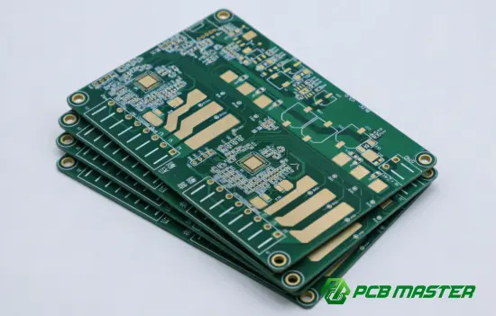
Heavy Copper PCB ’s are often used in high current battery management systems, to increase both the current carrying capacity and the heat dissipation. The thick copper layers reduce electrical resistance and prevent overheating during operation.
FR-4 PCBs are still widely used for BMS control circuits because of good electrical insulation, mechanical stability and low cost. They offer a secure platform for control elements, monitoring circuits and communication interfaces.
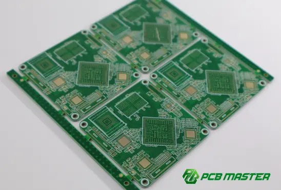
Higher component density is essential for compact and advanced BMS designs and HDI PCBs microvias, fine lines and optimized routing structures are well suited. This allows manufacturers to pack more function into a smaller footprint, reliably signalling.
The BMS PCBs must also address the challenges of high current capacity, thermal management, electrical reliability and compact circuit integration to ensure safe and efficient operation of the batteries in electric vehicles.
2. Inverter and Motor Controller
System Overview
The powertrain system in an electric car has two main components, the inverter and the motor controller. The battery pack stores and provides direct current (DC). The electric motor needs alternating current ( AC ) to operate . The inverter changes the battery 's direct current ( DC ) into alternating current ( AC ). It also decides how much energy the motor receives.
The motor controller controls the operation of the motor, controlling the speed, torque, acceleration and regenerative braking performance. High power levels. Severe electrical and thermal conditions. Therefore the PCB solutions used in the inverters and motor controllers should be reliable and have good heat management.
Main features are:
- DC to AC conversion: The battery delivers DC power, which is converted into the controlled AC output necessary for the electric motor.
- Motor Torque and Speed Control: Adjusts the power output to suit the driving situation and improve the vehicle’s performance.
- Energy management in operation: Control of the power flow between motor and battery, e.g. to support such functions as regenerative braking
PCB Types Used in Inverter and Motor Controller
Inverter and motor controller systems generate high voltage, high current and a lot of heat. This usually means that special PCB technologies are required:
- Heavy Copper PCB
- Ceramic PCB
- IMS (Insulated Metal Substrate) PCB
Why Are These PCB Types Used?
The inverter and motor controller PCBs need to be robust to resist electrical stress and stable in the harsh automotive environment.
Heavy Copper PCBs are commonly used in power electronics applications since they have thicker copper layers which are capable of handling high current flow and also reducing power loss. They also help to improve thermal performance by helping to spread heat away from high power components.
Ceramic PCBs are used in applications that require electrical insulation with high thermal conductivity. This enhances the heat dissipation and hence they are used in high power modules where stable operating temperature is required .
IMS PCBs are composed of a metal base layer, an insulating dielectric layer, and copper circuitry. They are a good thermal management solution for power electronics components. They electrically isolate the circuits from the metal substrate and dissipate heat well.
Inverter Motor Controller PCBs are demanding in terms of high voltage handling, high power density, excellent thermal conductivity, electrical insulation and long term durability for reliable EV performance.
3. On-Board Charger (OBC) and DC/DC Converter
System Overview
The major power conversion systems of electric vehicles are the On-Board Charger (OBC) and the DC/DC converter. The OBC is responsible for the charging process, where the AC power provided by external charging stations is converted to the DC power used by the battery pack and the DC/DC converter is responsible to control the voltage between the high voltage battery system and the low voltage electrical components.
The OBC ensures that the battery is charged safely and efficiently, and the DC/DC converter supplies stable power to systems such as vehicle control units, lighting, sensors and infotainment modules. Both systems are at high power levels, and are constantly converting electricity. Therefore the PCBs used in these applications must have excellent power handling capability, thermal performance and long-term reliability.
The main functions include:
- Charging of battery: Conversion of external AC power to suitable DC power for safe and efficient charging of the EV battery.
- Voltage Conversion: The auxiliary electronic systems require low-voltage levels, which are converted from the high-voltage battery.
- Power regulation: Providing a steady flow of energy so the vehicle's electronics can operate reliably.
PCB Types Used in OBC and DC/DC Converter
In general, the OBC and DC/DC converter systems require special PCB technologies because of the high power density and heat dissipation during operation. Such technologies are:
- Heavy Copper PCB
- Metal Core PCB
Why Are These PCB Types Used?
The OBC and DC/DC converter PCBs are required to have high electrical load capacity and stable performance under continuous operation.
Heavy Copper PCBs are widely used in power conversion applications. This is because of the thick thickness of copper which increases the current carrying capacity and reduces the electrical resistance. This will reduce power loss and increase the reliability of high current circuits.
Metal Core PCBs have a metal substrate that helps in heat dissipation as it gives a good heat conduction path away from the power components . This property makes them suitable for small power modules where heat dissipation is critical and thermal performance of traditional PCB materials may not be good enough.
OBC and DC/DC converter systems have excellent electrical performance and robust heat management, enabling high power density, efficient heat dissipation, stable power conversion, and long-term reliability under the stringent operating conditions of modern electric vehicles.
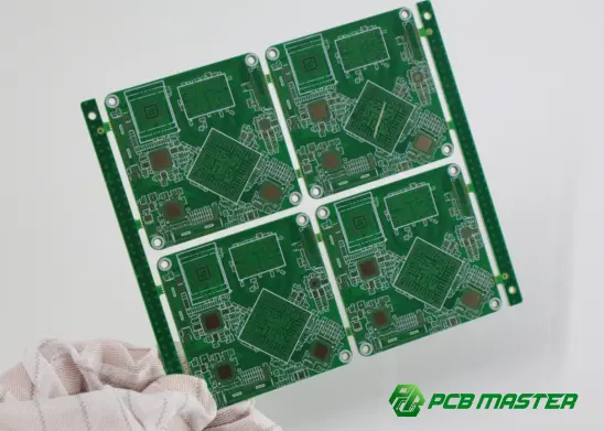
4. Advanced Driver Assistance Systems (ADAS)
System Overview
ADAS stands for Advanced Driver Assistance Systems . They are smart vehicle systems that improve driving safety, extend situational awareness and even support automated driving. ADAS uses information from several sensors and processes that data to provide capabilities such as adaptive cruise control, lane keeping assistance, automatic emergency braking and parking assistance.
ADAS systems today use a number of electronic components including:
- Cameras: They gather visual data for lane detection, recognition of traffic signs, detection of objects, etc.
- Radar: Can detect the speed and distance of surrounding vehicles and objects accurately under any weather or lighting conditions.
- Ultrasonic Sensors: Short range detection for obstacle detection and parking aid.
- AI Processors: Process vast quantities of sensor data in real-time to enable intelligent decision making and vehicle control.
Since ADAS needs high speed data processing and robust communication between multiple sensors and computer units, it is necessary that the PCBs used in such systems shall be able to support high density designs, high speed signal transmission and excellent electrical performance.
PCB Types Used in ADAS
The following are commonly used for ADAS applications to meet the requirements of small layout, high-speed data processing and reliable signal transmission:
- HDI PCB
- High-Speed PCB
- High-Frequency PCB
Why Are These PCB Types Used?
ADAS systems have complex processors, many sensors and high-speed communication interfaces in a limited space. Therefore, their PCBs need to have accurate control of signals and stable electrical performance.
HDI PCBs allow for a higher routing density with microvias and fine line patterns technologies. They enable the designer to pack more components and complex interconnections into tight ADAS modules, while still providing reliable signal paths.
High Speed PCB are used in applications where high speed data transfer is required between cameras, processors and communication interfaces. Controlled impedance design and optimized signal routing helps keep signal integrity and minimize transmission problems.
High Frequency PCBs are a critical for radar based ADAS applications especially for millimetre wave radar systems. These PCBs are made of low loss material and special design to ensure high frequency signals accurately transmitted and sensing performance consistently.
The main engineering challenges for ADAS PCBs are high routing density, signal integrity, controlled impedance, EMI suppression and high speed data transmission for reliable operation of modern intelligent driving systems.
5. Radar and Vehicle Communication Systems
System Overview
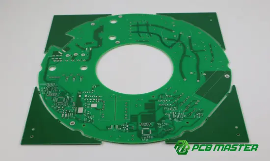
Since these systems rely on the transmission and processing of high-frequency signals, the PCBs used must maintain stable electrical performance while minimizing signal loss and interference.
The radar and vehicle-to-everything (V2X) communication systems are important to improve the vehicle perception, connectivity and intelligent driving capability. Such systems enable electric vehicles to sense the environment, communicate with external networks and provide reliable communication between the vehicle and other devices.
Applications are:
- Millimetre wave radar: This uses high frequency electromagnetic waves to sense distance, speed and motion of things. It is employed in several applications including adaptive cruise control, collision avoidance and autonomous driving features.
- V2X (Vehicle-to-Everything) communication: Data exchange between vehicles, infrastructure, pedestrians and networks for improving the traffic efficiency and the driving safety.
- GPS systems: GPS systems provide precise positioning data that can be used for navigation and location-based services.
- Telematics:Linking vehicles to remote monitoring, data communication and diagnostics.
- 5G communication: Higher data rate and more sophisticated connected vehicle services with lower latency.
These systems are based on the transmission and processing of high frequency signals so the used PCBs need to have an electrical performance stability and reduce the loss and the interference of signal.
PCB Types Used in Radar and Vehicle Communication Systems
The following applications are generally used due to the strict requirements of RF signal transmission:
- High-Frequency PCB
Why Are High-Frequency PCBs Used?
High frequency PCBs are used when signal accuracy and transmission reliability are the most important. High frequency PCB Materials are different from normal PCB Materials because they keep their electrical properties at high frequency. They are used in automotive radar and in communications applications.
For High Frequency transmission low dielectric loss is required to reduce the attenuation of the signal so that the signals can propagate with minimum loss of energy.
The radar and communication modules provide robust RF performance for precise sensing and reliable connectivity across a wide range of environmental conditions.
The PCBs are capable of transmitting signals at high frequencies and are therefore suitable for Millimetre wave radar, wireless communication and advanced vehicle connectivity systems.
This is especially the case in radar applications where even small differences can affect fidelity of object detection and measurement reliability. Therefore, high frequency PCBs nowadays are critical to the radar sensing accuracy, reliable communication and stable RF performance of electric vehicles.
6. Cameras, Displays, and Intelligent Cockpit
System Overview
The cameras, displays and smart cockpit systems in today’s EVs are all designed to give drivers better visibility, information displays and interactive experiences. With the increasing number of connected and smart EVs, these systems are requiring increasingly sophisticated electronic architectures to process the large data volumes and to facilitate real-time communication.
Standard use is:
- Surround view cameras: These cameras capture images from multiple angles to provide a 360-degree view around your vehicle. This is useful for parking, for seeing blind spots and for general awareness when driving.
- Digital instrument clusters: Analogue gauges are replaced by digital screens that display real-time information such as speed, battery charge, navigation and driving stats.
- Infotainment systems:Combine multimedia, navigation, wireless connectivity and vehicle controls.
- Head-up displays (HUDs): Project key driving information onto the windshield so drivers can see it without taking their eyes off the road.
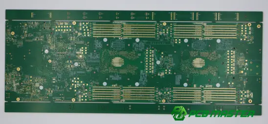
The systems are built on compact electronic assemblies, thus the PCBs used have to offer high density layouts, reliable signal transmission and flexible installation requirements.
PCB Types Used in Cameras, Displays, and Intelligent Cockpit Systems
These are typically built small in size with state-of-the-art functionality and high-velocity communication capabilities using:
- HDI PCB
- High-Speed PCB
- Flexible PCB
- Rigid-Flex PCB
Why Are These PCB Types Used?
Today’s camera modules, displays and cockpit electronics PCBs are expected to fit more functions into a smaller space while still providing reliable electrical performance.
HDI PCBs can fit components at high density with microvia technology and fine traces. This is a perfect match for compact modules such as a camera system, display controllers and advanced infotainment units.
High Speed PCBs are used in systems that requires data transfer at high-speed such as high resolution cameras, digital displays and multimedia processors. The proper routing and impedance control of the signals guarantee the signal integrity and communication between the components.
Flexible PCs are very flexible in their design, as they are bendable and can be placed in irregular areas. These are often used because it is difficult to fit conventional rigid boards into tightly packed electronic modules.
Rigid-flex PCBs offer the mechanical strength of a rigid board, and the ability to bend like a flexible circuit, eliminating connectors and improving reliability in automotive applications where space is at a premium.
These PCB technologies combined allow miniaturization, flexible installation, weight reduction and high speed interfaces to lay the foundation for smarter more connected electric vehicle cockpits.
7. Automotive LED Lighting Systems
System Overview
Automotive LED lighting systems are the latest technology in electric vehicles, providing improved visibility, energy saving and vehicle design. LEDs last longer, use less energy and give more design flexibility than traditional lighting technologies. LED components produce a large amount of heat during operation, therefore proper heat management is very crucial to maintain the performance and reliability of the LED.
Typical LED lighting applications in EVs include:
- Headlights: Illuminate the road ahead to allow for safe operation of the vehicle. They can also have advanced features like adaptive lighting and automatic beam control.
- Tail lights:Improves visibility of the vehicle to other road users and provides signalling functions related to safety.
- Daytime Running Lights (DRLs): Enhance vehicle visibility during daytime driving and offer a modern automotive design feature.
- Interior Lighting: Offers ambient and functional lighting options within the vehicle such as dashboard, door and cabin lighting.
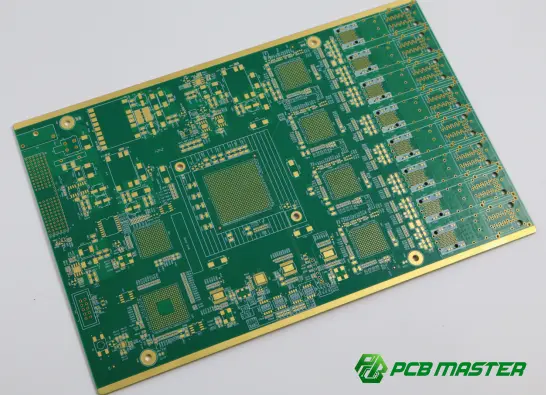
The operating temperature has a significant effect on the performance of LED. Therefore, the PCBs used in automotive lighting systems are required to have a stable electrical performance and to be able to transfer heat away from the LED components in an efficient way.
PCB Types Used in Automotive LED Lighting Systems
They are used in automotive LED lighting applications due to their excellent thermal management ability:
- Aluminum PCB
- Metal Core PCB (MCPCB)
Why Are These PCB Types Used?
The LED lighting system requires the use of PCB solutions that can withstand the continuous heat generation and offer reliable operation during the lifetime of the vehicle.
Aluminium PCBs have a metal base that helps in better heat dissipation from the LED components to the environment. This helps to prevent excess temperature build-up, thereby improving lighting stability and extending the LED service life.
Metal Core PCBs (MCPCBs) are manufactured with a metal core layer that has a higher thermal conductivity than traditional FR-4 materials. They are also extensively used in high power LED applications where heat dissipation is critical.
These PCB technologies improve thermal management with uniform lighting performance under various operating conditions. Therefore, aluminium and metal core PCBs are used in automotive LED lighting systems to ensure efficient heat dissipation, longer LED life and stable thermal behaviour to ensure reliable lighting performance during the service life of the vehicle.
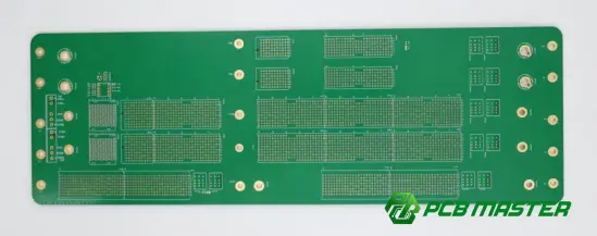
8. Body Electronics and Electronic Control Units (ECUs)
System Overview
Body electronics and electronic control units (ECUs) perform many comfort, convenience and support functions in today’s electric vehicles. They don’t usually operate at the power levels of battery systems or motor controllers, but they are essential in coordinating vehicle operations and enhancing the user experience.
Common applications include:
- Body Control Module (BCM):Manages functions like lighting, door locking, and vehicle system communications.
- Heating, Ventilation and Air Conditioning (HVAC): Confirms that the heating, ventilation and air conditioning functions are working to ensure passenger comfort and improve energy efficiency.
- Power windows - operates the window motors and related safety functions.
- Door control systems Operate electronic door systems (lock, sensors and access systems).
- Seat control systems: Support electrically adjustable seats and related comfort features.
- Mirror control systems. Electronic fold and heat of the outside mirrors.
As cars become smarter, these body electronics systems need sophisticated electronic control and communication capabilities. For these applications the PCBs should be robust, cost effective to manufacture and stable.
PCB Types Used in Body Electronics and ECUs
Typical PCB solutions are dependent on the complexity and functional requirements of the system:
- Standard FR-4 PCB
- HDI PCB (for advanced ECU designs)
Why Are These PCB Types Used?
For body electronics and ECUs, PCB technologies must balance performance, reliability and manufacturability.
Automotive control modules generally use standard FR-4 PCBs , due to their good electrical insulation, mechanical stability and cost effectiveness. Their mature manufacturing process and proven reliability make them the ideal choice for high volume automotive applications.
Advanced ECU designs are using HDI PCBs because of the need to fit more features into a smaller space. HDI PCBs use fine line routing and microvia technology to provide higher component density and more complex electronic designs.
Power electronics systems are different to body control applications which require more current but need to be reliable for the life of the vehicle in conditions such as vibration, temperature variation and environmental exposure.
Thus, the PCB solutions for body electronics and ECUs emphasize cost efficiency, reliable operation, mature manufacturing processes and long service life to support the growing electronic integration of modern electric vehicles.
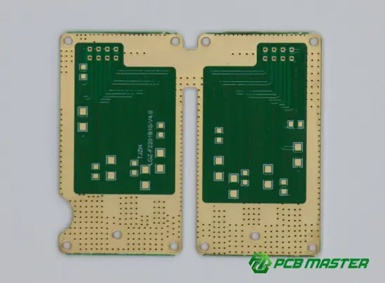
Conclusion
Because electric vehicles are based on many electronic systems and each system has its own unique performance requirements. Hence different PCB technologies are required to solve specific problems such as high current handling, thermal management, signal integrity, space limitations and long term reliability. Every technology is customized for different EV applications including battery management, power conversion, intelligent driving, communication and vehicle control systems from Heavy Copper PCB and HDI PCB to High Speed, High Frequency, Metal Core, Flexible, Rigid-Flex and Ceramic PCB solutions.
As the automotive industry moves forward with 800V high voltage platforms, advanced driver assistance systems and connected vehicle technologies, the need for high performance and very reliable automotive PCBs will only grow. As an experienced PCB and PCBA manufacturer, PCBMASTER offers reliable PCB and PCBA solutions for a range of electric vehicle applications to support customers with high-quality products, advanced manufacturing capabilities and professional engineering expertise.
FAQs
1. How many PCB’s in an electric car?
The amount of PCBs used in an electric vehicle depends on the design of the vehicle, electronic features and level of intelligence . Today many EVs have numerous PCB assemblies in the core systems of battery management, power electronics, driver assistance, communication, infotainment and body control modules. As cars become smarter and more electrified, the need for sophisticated automotive PCB solutions is increasing.
2.What is the common PCB material for EV battery management system?
The most used PCBs in the Battery Management System (BMS) are Heavy Copper, FR-4 and HDI PCBs. Power management and battery monitoring heavy copper PCBs with enhanced thermal properties and current carrying capacity. FR-4 PCBs are mostly used in control circuits because of their electrical insulation, mechanical stability and low cost. HDI PCBs offer better integration of circuits and higher component density needed for small and advanced BMS designs.
3. Why are heavy copper PCBs important in electric vehicles?
Heavy Copper PCBs are vital for electric vehicles as many EV power systems have to deal with high current and heat management. More copper means less electrical resistance and a better ability to carry current. It also dissipates heat created in use. As a result, heavy copper PCBs are commonly used in high power applications, such as battery management systems, inverters, onboard chargers, and DC/DC converters.
4. Why automotive radar system needs high frequency PCB?
Automotive radar systems use high-frequency signals to determine the distance, speed and motion of an object accurately. High-Frequency PCBs are constructed using special low-loss materials to reduce signal loss and maintain RF performance at high frequencies. These are essential features for accurate sensing, robust communication and stable performance of the millimeter-wave radar for advanced driver assistance systems (ADAS).
5. What Certification Should the Automotive PCB Maker Have?
A PCB manufacturer for the automotive industry must have certifications and quality systems to prove its reliability in manufacturing ability and quality control. Some common certifications are IATF 16949 (automotive quality management), ISO 9001 (quality management systems), UL certification (safety compliance) and RoHS compliance (environmental requirements). Besides certifications, automotive PCB suppliers need strong process controls, reliability testing capabilities and a proven track record of delivering high-performance PCB solutions for demanding automotive applications.
About the Author

Carol Luo
PCB Design EngineerI'm Carol, a PCB Engineer at PCBMASTER with experience in PCB design and manufacturing engineering since 2018. I focus on translating engineering requirements into reliable PCB solutions, with expertise in stack-up design, material selection, and design-for-manufacturing (DFM). I share practical engineering insights from real-world PCB design and production experience.
Visit Carol Luo's Profile