








What Is a Resistor in a Circuit? A Complete Guide to Its Function, Types, and Applications
A resistor is a passive electronic component that limits or regulates the flow of electric current in a circuit. Its resistance, measured in ohms (Ω), determines how much current flows for a given voltage. Resistors are fundamental to PCB and PCBA design because they are used for current limiting, voltage division, signal conditioning, biasing, termination, and power management. Understanding how resistors work is essential for designing reliable electronic circuits.
What Is a Resistor in a Circuit?
A resistor is a passive electronic component designed to oppose the flow of electric current .
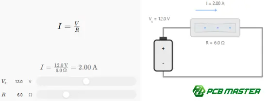
When a voltage is applied across a resistor, the resistor limits the resulting current according to Ohm's law :
I= V/R
where:
- I = current in amperes (A)
- V = voltage in volts (V)
- R = resistance in ohms (Ω)
For example, if a 10 V source is connected to a 1 kΩ resistor, the current through the resistor is 10 mA.
The resistor does not normally store electrical energy like a capacitor or inductor. Instead, it dissipates electrical energy primarily as heat .
This simple behavior makes resistors one of the most widely used components in electronic circuits.
What Does a Resistor Do in a Circuit?
A resistor can perform several different functions depending on where it is placed and how its value is selected.
1. Limit Current
One of the most common applications is current limiting .
For example, an LED typically requires a resistor to prevent excessive current from flowing through it. Without appropriate current limiting, the LED may be damaged.
A simplified circuit can be represented as:
Voltage source → Resistor → LED → Ground
The resistor absorbs part of the available voltage and controls the current reaching the LED.
2. Divide Voltage
Two or more resistors can create a voltage divider .
For two resistors connected in series, the output voltage across the second resistor is:
Vₒᵤₜ = Vᵢₙ [R₂ /(R₁ +R₂ )]
Voltage dividers are frequently used to reduce a voltage to a level suitable for an ADC, sensor input, microcontroller, or other circuit.
3. Set Circuit Bias
Resistors can establish the operating point of transistors, operational amplifiers, and other semiconductor devices.
For example, resistor networks are commonly used to establish the voltage applied to the base of a BJT or the gate of certain transistor circuits.
4. Pull Signals High or Low
Digital circuits often use pull-up and pull-down resistors .
A pull-up resistor connects a signal line to a positive supply voltage, while a pull-down resistor connects it to ground.
These resistors prevent an input from being left in an undefined floating state when no active device is driving the signal.
5. Terminate High-Speed Signals
In high-speed PCB designs, resistors can also be used for signal termination .
Poorly terminated transmission lines can experience reflections, ringing, overshoot, and undershoot. Appropriate termination resistance can help control signal integrity.
The resistor value therefore becomes part of the overall electrical design rather than simply a current-limiting component.
6. Dissipate Electrical Power
Some resistors are specifically selected to handle significant amounts of power.
The power dissipated by a resistor can be calculated as:
P=VI
It can also be expressed as:
P= I² R
or
P= V² /R
The resistor's power rating must be higher than the expected operating power , with an appropriate design margin.
How Does a Resistor Work?
At the physical level, resistance results from the interaction between moving charge carriers and the material through which they travel.
When current flows through a resistive material, electrical energy is converted into thermal energy.
The resistance of a uniform conductive material depends on several physical factors:
R=ρL / A
where:
- ρ = resistivity of the material
- L = length of the conductive path
- A = cross-sectional area
Therefore, resistance generally increases when the conductive path becomes longer and decreases when its cross-sectional area becomes larger.
The material itself also matters. Different materials have different resistivities, which is why resistor construction uses carefully selected resistive materials to achieve specific electrical characteristics.
What Are the Main Types of Resistors?
Resistors can be classified according to construction, operating characteristics, and application.
Fixed Resistors
A fixed resistor has a predetermined resistance value.
Common values include:
- 10 Ω
- 100 Ω
- 1 kΩ
- 10 kΩ
- 100 kΩ
- 1 MΩ
Fixed resistors are widely used in PCB assemblies because they are inexpensive, compact, reliable, and available in many package sizes.
Variable Resistors
A variable resistor allows its resistance to be adjusted.
Examples include:
- Potentiometers
- Trimmer potentiometers
- Rheostats
Variable resistors are useful when a circuit needs manual or calibrated adjustment.
Thermistors
A thermistor changes resistance according to temperature.
Two common categories are:
- NTC thermistors— resistance decreases as temperature increases.
- PTC thermistors— resistance increases as temperature increases.
They can be used for temperature sensing, compensation, and circuit protection.
Photoresistors
A photoresistor , also known as an LDR, changes resistance according to the amount of incident light.
It can be used in light-detection circuits and automatic lighting systems.
Current-Sense Resistors
A current-sense resistor is designed to have a very low and accurately controlled resistance.
The voltage developed across the resistor can be measured to determine the current flowing through a circuit.
These components are particularly important in power electronics, battery management systems, motor control, and other applications where current monitoring is required.
How Are Resistors Connected in a Circuit?
The way resistors are connected significantly affects the circuit's total resistance.
Resistors in Series
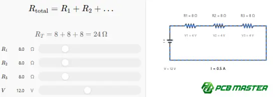
When resistors are connected end-to-end in series, their equivalent resistance is:
Rₜₒₜₐₗ = R₁ +R₂ + ⋯+Rₙ
For example:
| Resistor | Resistance |
|---|---|
| R1 | 100 Ω |
| R2 | 220 Ω |
| R3 | 330 Ω |
| Total | 650 Ω |
The same current flows through each resistor in an ideal series circuit, while the total voltage is distributed among the resistors.
Resistors in Parallel
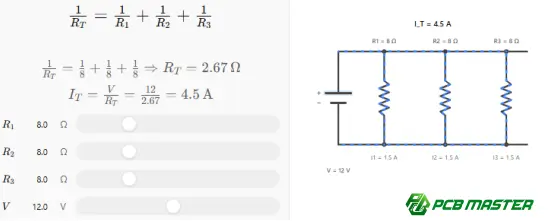
When resistors are connected in parallel, the equivalent resistance is calculated as:
1/Rₜₒₜₐₗ =1/R₁ +1/R₂ +⋯+ 1/Rₙ
For two equal 1 kΩ resistors connected in parallel, the equivalent resistance is 500 Ω.
In a parallel circuit, each branch experiences the same voltage, while the total current is divided among the branches.
What Is Resistance Measured In?
Resistance is measured in ohms , represented by the symbol Ω .
Common resistance units include:
| Unit | Symbol | Equivalent |
|---|---|---|
| Ohm | Ω | 1 Ω |
| Kilohm | kΩ | 1,000 Ω |
| Megohm | MΩ | 1,000,000 Ω |
The resistance value printed on or encoded into a resistor tells the designer how strongly the component will oppose current flow.
For surface-mount resistors, the value may be represented by a numerical code rather than a full resistance value.
How Do You Read a Resistor Value?
Traditional through-hole resistors often use color bands to identify their resistance value and tolerance.
For example, a four-band resistor typically uses:
- First significant digit
- Second significant digit
- Multiplier
- Tolerance
Surface-mount resistors commonly use numerical markings, although very small components may have no visible marking because of their limited physical dimensions.
When manufacturing a PCB assembly, the resistor's value must match the bill of materials (BOM) and PCB assembly data.
Incorrect resistor values can cause problems ranging from inaccurate sensor readings to complete circuit malfunction.
What Is Resistor Tolerance?
No physical resistor has a perfectly exact resistance value.
Tolerance specifies how much the actual resistance can deviate from its nominal value.
For example, a 1 kΩ resistor with ±5% tolerance can theoretically have an actual resistance between:
- 950 Ω
- 1,050 Ω
Common tolerance values include:
- ±10%
- ±5%
- ±1%
- ±0.5%
- ±0.1%
Precision applications may require tighter tolerances because even a small resistance variation can affect circuit performance.
Why Is Resistor Power Rating Important?
Resistance value alone is not enough when selecting a resistor.
The designer must also consider power dissipation .
Suppose a resistor dissipates 0.5 W continuously. Using a resistor rated for exactly 0.5 W leaves essentially no margin for temperature, environmental variation, or design uncertainty.
A resistor with a higher power rating may therefore be more appropriate.
Common Resistor Specifications
| Parameter | What It Determines |
|---|---|
| Resistance | How strongly current is opposed |
| Tolerance | Allowed deviation from nominal resistance |
| Power rating | Maximum rated power dissipation |
| Temperature coefficient | Resistance change with temperature |
| Package size | Physical dimensions and PCB footprint |
| Voltage rating | Maximum applicable voltage |
| Construction | Electrical and environmental characteristics |
A correct resistor selection requires evaluating all relevant parameters rather than choosing the resistance value alone.
How Are Resistors Used on PCBs?
Resistors are among the most common components found on printed circuit boards.
They can appear in:
- Power supply circuits
- Microcontroller boards
- Communication equipment
- Automotive electronics
- Industrial control systems
- Consumer electronics
- Medical electronics
- Battery management systems
- RF and high-speed circuits
- Sensor interfaces
On a PCB, the resistor must be matched not only to the electrical schematic but also to the PCB footprint, assembly process, thermal environment, voltage requirements, and manufacturing specifications .
For surface-mount technology (SMT) , package selection is particularly important.
Common SMD resistor package sizes include:
- 0201
- 0402
- 0603
- 0805
- 1206
Smaller packages can save board space but may introduce greater manufacturing and inspection challenges.
Common Mistakes When Selecting a Resistor
Choosing the Correct Resistance but the Wrong Power Rating
A resistor may have the correct resistance but fail because its power rating is insufficient.
Avoidance: Calculate expected power dissipation and select an appropriate rating with engineering margin.
Ignoring Tolerance
A circuit requiring precision measurement may not perform correctly with a resistor having excessive tolerance.
Avoidance: Determine the required resistance accuracy before selecting the component.
Using the Wrong PCB Footprint
A resistor with the correct electrical value can still create assembly problems if the PCB footprint does not match the component package.
Avoidance: Verify the manufacturer's component dimensions and PCB land pattern.
Selecting Components Without Considering Temperature
Resistance can vary with temperature.
Avoidance: Evaluate the resistor's temperature coefficient and expected operating temperature range for precision or temperature-sensitive applications.
Treating High-Speed Resistors Like Ordinary Components
At high frequencies, parasitic inductance and capacitance can affect resistor behavior.
Avoidance: Consider package geometry, placement, impedance, routing, and termination strategy when designing high-speed circuits.
What Is the Difference Between a Resistor and Other Passive Components?
| Component | Primary Function | Energy Behavior |
|---|---|---|
| Resistor | Limits current and establishes voltage relationships | Dissipates energy as heat |
| Capacitor | Stores electrical charge | Stores energy in an electric field |
| Inductor | Opposes changes in current | Stores energy in a magnetic field |
These components can work together to create filtering, timing, power conditioning, impedance matching, and signal-processing circuits.
For example, combining a resistor and capacitor can create an RC low-pass filter , which attenuates high-frequency signals while allowing lower-frequency signals to pass.
Practical PCB Design Considerations for Resistors
A resistor's electrical characteristics are only one part of a successful PCB design.
Engineers should also consider:
Placement
Place resistors close enough to the associated components to minimize unnecessary routing and parasitic effects.
Thermal Management
Power resistors may generate significant heat. Adequate copper area and thermal considerations may be necessary to prevent excessive temperature rise.
Signal Integrity
For high-speed interfaces, resistor placement can influence impedance discontinuities and signal reflections.
Manufacturing
The selected package must be compatible with the PCB assembly process and component availability.
DFM Verification
Before production, PCB design files should be checked for:
- Component footprints
- Component spacing
- Polarity requirements
- BOM consistency
- Soldering considerations
- Manufacturing constraints
Professional engineering review can identify these issues before they reach production.
PCBMASTER's Approach to PCB and PCBA Manufacturing
As a PCB and PCBA manufacturer serving applications across multiple industries, PCBMASTER integrates PCB fabrication, PCBA assembly, SMT, component sourcing, and engineering support into a one-stop manufacturing process.
Its engineering team provides free engineering file checking , reviewing design files for manufacturability, PCB performance, and cost-effectiveness before production. This is particularly relevant when resistor footprints, component placement, BOM information, and assembly requirements need to be verified together.
PCBMASTER operates an 80,000 m² factory and supports standard and advanced PCB technologies, including HDI , FPC , rigid-flex , high-frequency PCB , and metal-core PCB manufacturing. Its quality systems are supported by ISO 9001, IATF 16949, UL, and RoHS certifications .
For applications involving precision resistor networks, power electronics, high-speed signals, or complex SMT assemblies, the manufacturing process needs to consider the complete relationship between the component, PCB design, assembly process, and final electrical performance.
Resistor Selection Checklist
Before selecting a resistor for a circuit, engineers should verify:
- Resistance value
- Tolerance
- Power rating
- Operating voltage
- Temperature coefficient
- Operating temperature
- Package size
- PCB footprint
- Mounting technology
- Application frequency
- Required reliability
- Component availability
For high-volume PCB assembly, designers should also consider whether the selected resistor is suitable for automated SMT placement and reflow soldering.
Conclusion: Why Are Resistors Important in Circuits?
A resistor is a fundamental passive electronic component that controls current, divides voltage, establishes bias conditions, provides signal termination, and dissipates electrical energy .
Although a resistor is physically simple, selecting the right one requires more than identifying an ohmic value. Resistance, tolerance, power rating, temperature coefficient, package, voltage rating, and circuit frequency can all affect real-world performance.
For PCB designers and electronics engineers, understanding resistor behavior is therefore a foundational part of circuit design. For manufacturers, accurate component sourcing, PCB fabrication, SMT placement, soldering, inspection, and engineering verification are equally important for turning the circuit design into a reliable finished PCBA.
As electronic systems become more compact and increasingly dependent on high-speed communication and power-efficient architectures, resistor selection and PCB implementation will continue to be closely connected to overall system performance.
Tags: #Resistor #WhatIsAResistor #ResistorInCircuit #CircuitDesign #Electronics #PCB #PCBA #SMT #PCBDesign #ElectronicComponents #ElectronicsEngineering
About the Author

Carol Luo
PCB Design EngineerI'm Carol, a PCB Engineer at PCBMASTER with experience in PCB design and manufacturing engineering since 2018. I focus on translating engineering requirements into reliable PCB solutions, with expertise in stack-up design, material selection, and design-for-manufacturing (DFM). I share practical engineering insights from real-world PCB design and production experience.
Visit Carol Luo's Profile

