


Understanding PCB Shrinkage Factors: How Material, Design, and Environment Affect Size Stability
PCB shrinkage can be a silent yet powerful force, wreaking havoc on production efficiency and product quality. Even minor changes in a PCB’s dimensions can lead to misalignments, component placement errors, and ultimately failure in critical applications. While the problem may seem complex, it all boils down to a range of interconnected factors—from the materials used to the processes that shape them. Understanding these forces is key to minimizing shrinkage and enhancing overall performance. By tackling the root causes head-on, manufacturers can improve yield rates, optimize designs, and produce more reliable, high-quality PCBs.
What is PCB Shrinkage?
PCB shrinkage refers to the dimensional instability that occurs during the manufacturing and usage of printed circuit boards (PCBs). This phenomenon happens when a PCB’s size changes due to various internal and external factors such as temperature, humidity, material properties, and manufacturing processes. The result is that the dimensions of the PCB either expand or contract, which can significantly impact its performance and reliability.
In a typical PCB, shrinkage usually happens due to thermal expansion during soldering or temperature fluctuations. The materials that make up the PCB—such as resin, copper, and glass fibers—expand or contract at different rates when exposed to heat, which can cause the board to warp, bend, or shift in shape.
Example: Think of it like a sponge that shrinks or expands when exposed to water or heat. Similarly, a PCB "shrinks" or "expands" based on the conditions it's exposed to, and this can lead to problems like improper alignment of layers or incorrect component placement.
Impact on Dimensional Stability, Assembly Accuracy, and Performance
PCB shrinkage can have a significant impact on the overall functionality of a circuit board. These impacts can be categorized into three main areas: dimensional stability, assembly accuracy, and performance.
Dimensional Stability: Shrinkage alters the dimensions of the PCB, which can cause issues such as misalignment between layers. For multi-layer PCBs, precise alignment is crucial for proper functionality. Shrinkage can lead to gaps or overlaps between the layers, affecting both electrical and mechanical connections.
Assembly Accuracy: When a PCB shrinks or expands, it changes the distance between the components or the vias (small holes that connect different layers). This can result in poor component placement, which might lead to soldering issues or miscommunication between parts.
Performance: A warped or distorted PCB will not fit properly in the intended housing or system, which can cause stress on the components. In extreme cases, this can lead to component failure or poor signal integrity, affecting the PCB's overall performance.
Real-life example: Imagine a PCB in a smartphone. If the PCB shrinks due to heat, the small components like resistors or capacitors could shift, causing a malfunction or short circuit. This would directly impact the performance of the device, leading to poor user experience or failure.
What are the main factors affecting PCB shrinkage?
PCB shrinkage is influenced by several factors, including material properties, design, manufacturing processes, and environmental conditions. From differences in thermal expansion to moisture absorption, each element affects how much a PCB can shrink or warp. Understanding these factors is essential for minimizing shrinkage and improving PCB performance.
Material Factors
1. Thermal Expansion Coefficient (CTE) Differences and Their Impact
The thermal expansion coefficient (CTE) measures how much a material expands or contracts when exposed to temperature changes. PCB shrinkage often occurs because different materials used in the PCB have different CTE values. Copper and the base material (like FR-4) expand and contract at different rates when exposed to heat. For example, copper has a low CTE, while FR-4 can have a much higher CTE. This difference creates internal stress within the PCB, leading to warping or shrinkage.
Real-life example: Imagine a metal rod and a rubber band. When both are heated, the metal expands less than the rubber band, causing tension. Similarly, in a PCB, when heat is applied, the copper and the base material expand at different rates, leading to shrinkage or distortion.
2. Glass Fiber Weave Differences
PCB base materials often contain glass fibers, which are woven in two directions: the warp (length) and the weft (width). These two directions have different fiber densities and thermal expansion properties. The warp direction is tighter and more resistant to expansion, while the weft is looser and more susceptible to changes in size. This causes dimensional differences across the board, contributing to shrinkage.
Real-life example: Think of the difference between stretching a tightly held rubber band (warp) and a loosely held one (weft). The loose band stretches more, just like the weft fibers of a PCB.
3. Moisture Absorption and Water Evaporation
Some PCB materials, especially certain resins, are hygroscopic, meaning they absorb moisture from the environment. When exposed to heat, this moisture evaporates, causing the material to expand or deform. This is a common issue in high-humidity environments, especially during the soldering process.
Real-life example: Similar to how a wet sponge expands as it dries, a moisture-absorbing PCB can expand as its water content evaporates during manufacturing, leading to shrinkage.
4. Uneven Copper Foil Distribution
Copper is commonly used in PCB construction, and its uneven distribution on the board can create localized stress points. High-density areas, such as where there are a lot of traces, and areas with little or no copper can lead to uneven expansion or contraction during heating, causing warping.
Real-life example: Consider a piece of cloth with patches of different material thicknesses. When heated, the thinner areas will expand more, causing distortion. This happens in a PCB when copper is unevenly distributed.
5. Special Materials and Board Types
Some PCBs use special materials like high-frequency boards (such as PTFE) or thin HDI (High-Density Interconnect) boards. These materials have unique properties that can make them more prone to shrinkage. For example, PTFE is more flexible and has a higher CTE, making it more susceptible to dimensional changes during heating. HDI boards, being thinner, are more sensitive to thermal changes and can warp more easily.
Real-life example: Think of PTFE as a soft plastic, which stretches more under heat than a rigid material like steel. HDI boards, being thin like paper, can bend or warp more than thicker boards.
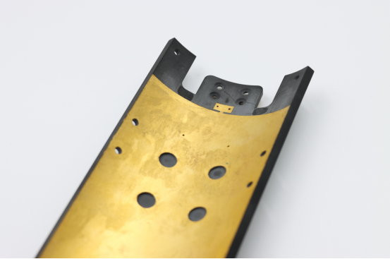
6. Mixed-Layer Structures (e.g., FR-4 with Metal Substrate)
Mixing different materials with varying CTEs, such as combining FR-4 with a metal substrate, increases the risk of shrinkage due to the differing thermal expansion rates. This can lead to cracks or deformations at the interface between the materials.
Real-life example: If you were to bake two materials at different rates—one material expands faster than the other—the interface might crack or bend due to the differing expansion rates. This happens in mixed-layer PCBs when different materials are used together.
Design and Process Factors
1. Stress Control in Lamination
During PCB lamination, layers of material are pressed together under heat and pressure. If the process is not carefully controlled, uneven stress can remain trapped inside the board. This residual stress can later result in shrinkage or warping as the PCB cools or undergoes other manufacturing processes.
Real-life example: Think of rolling dough. If the dough isn’t rolled evenly, some areas will rise more than others, causing uneven baking. Similarly, an improperly laminated PCB can have uneven stress, leading to shrinkage.
2. Stress Release During Etching and Pattern Transfer
In PCB manufacturing, copper is often etched away to create the circuit patterns. This process can release internal stress from the copper, causing the PCB to deform or shrink. Improperly etched areas can lead to uneven shrinkage in the board.
Real-life example: Imagine a balloon with uneven pressure inside. If you let out some air unevenly, the balloon will change shape. In PCBs, uneven etching can lead to similar changes in shape and size.
3. Drilling and Mechanical Processing Stress
Drilling and other mechanical operations on PCBs generate mechanical stress, which can distort the board. Drilling holes for vias (connections between layers) or cutting the PCB can weaken the material at specific points, leading to localized shrinkage or warping.
Real-life example: Think of poking a hole in a piece of paper. The paper will stretch or bend around the hole. Similarly, drilling in a PCB creates stress points that can lead to shrinkage.
4. Material Softening and Thermal Expansion During High-Temperature Processes
High-temperature processes, like soldering or reflow soldering, can soften the materials of the PCB. This softening, combined with the thermal expansion of the materials, can lead to shrinkage, especially if the temperature is not carefully controlled.
Real-life example: Imagine heating a piece of clay. It softens and changes shape. Similarly, heat during PCB manufacturing can soften the material, causing it to shrink or warp if not managed correctly.
Environmental and Storage Factors
1. Temperature and Humidity Variations
Changes in temperature and humidity can have a major impact on PCB materials. High humidity levels can cause moisture absorption, while temperature fluctuations can lead to expansion and contraction of the materials, causing shrinkage. This is especially critical in regions with extreme climate conditions or when PCBs are stored improperly.
Real-life example: Just as wood expands and contracts with moisture changes, a PCB made from moisture-absorbing materials can swell or shrink depending on environmental conditions.
2. Moisture Absorption During Storage and Steam Pressure
If a PCB absorbs moisture during storage, it can expand. When exposed to heat during manufacturing, the moisture inside the PCB turns to steam and creates internal pressure. This pressure can cause the PCB to deform or shrink in unpredictable ways.
Real-life example: Imagine a balloon filled with air and water. As the balloon heats up, the water turns to steam and the balloon expands or deforms. Similarly, moisture inside a PCB can cause it to shrink or warp when exposed to heat.
3. Stress Release During Storage
PCBs may experience internal stress during manufacturing, which may not be immediately visible. Over time, this stress can be released during storage, leading to slow and gradual deformation or shrinkage.
Real-life example: Think of a spring that has been compressed. Over time, it will gradually release the tension and return to its original shape. Similarly, internal stress in a PCB can slowly release, causing shrinkage over time.
Shape Factors
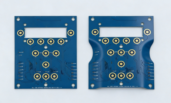
1. Internal Stress in Long Rectangular PCBs
Long, rectangular PCBs are more susceptible to shrinkage due to their shape. The length of the board means that internal stress is not distributed evenly across the entire surface. When heat is applied, the board can bend or warp, especially if one side expands more than the other.
Real-life example: Imagine a long piece of metal being heated. If one end expands more than the other, it will warp. This happens in long rectangular PCBs when different sections expand unevenly.
2. Comparison with Square PCBs
Square PCBs, being more symmetrical, are less likely to experience significant shrinkage compared to long rectangular boards. The even distribution of stress makes them more stable and predictable in terms of dimensional changes.
Real-life example: Think of a perfectly square piece of paper versus a long, narrow strip. The square piece is less likely to bend or warp when exposed to heat, whereas the long strip is more likely to distort.
How to Control PCB Shrinkage?
Controlling PCB shrinkage is essential for maintaining the quality and reliability of printed circuit boards. By addressing key factors like material selection, manufacturing processes, environmental conditions, and design choices, manufacturers can significantly reduce shrinkage and its impact. Let’s explore practical strategies to manage PCB shrinkage and ensure optimal performance.
Material Selection and Optimization
Choosing Materials with Similar Thermal Expansion Coefficients (CTE)
The first step in controlling PCB shrinkage is selecting materials that have a similar thermal expansion coefficient (CTE). CTE measures how much a material expands or contracts when exposed to temperature changes. If the materials used in the PCB have significantly different CTE values, such as copper and FR-4, this can cause internal stress, leading to shrinkage. By selecting materials with more comparable CTEs, manufacturers can minimize this stress, reducing the likelihood of PCB warping or shrinking.
Real-life example: Think of using two types of fabric for a jacket—one stretches a lot when heated, while the other doesn’t. The mismatch in stretching can cause the jacket to twist. In a PCB, using materials with similar CTE values ensures the board expands and contracts more evenly.
Process Parameter Optimization
Controlling Lamination, Etching, and Drilling Processes to Minimize Stress
The manufacturing processes, such as lamination, etching, and drilling, play a significant role in controlling PCB shrinkage. For example, during lamination, improper temperature or pressure can leave residual stress in the material, leading to shrinkage. Similarly, during etching, uneven removal of copper can cause internal stress. Drilling can also add stress, especially in areas where vias or holes are created. By optimizing these processes—using correct temperatures, pressure, and times—manufacturers can reduce the internal stress that leads to shrinkage.
Real-life example: Consider baking a cake. If the oven temperature fluctuates or the cake is moved too soon, it can collapse. Similarly, by ensuring stable conditions during PCB processing, stress is minimized, preventing shrinkage.
Environmental Control
Maintaining Stable Temperature and Humidity Conditions
Environmental factors like temperature and humidity can directly affect the materials of the PCB. High humidity can cause moisture absorption, while temperature fluctuations can lead to thermal expansion or contraction. To control shrinkage, manufacturers should maintain consistent temperature and humidity conditions in both the production environment and during storage. Additionally, managing the release of internal stress after PCB processing is crucial. Proper cooling and handling reduce the risk of deformation over time.
Real-life example: Think of storing a piece of clay. If it’s left in a humid place, it will soften and change shape. By controlling the environment, the clay can stay firm and hold its shape—just like a PCB in a controlled environment.
Shape Design
Reducing Deformation in Long Rectangular PCBs
Long, rectangular PCBs are more prone to shrinkage because internal stress is not evenly distributed. To reduce deformation, designers can use strategic support during the manufacturing and cooling processes. Reinforcing the PCB with additional supports or using specific processing techniques can help keep the shape intact. For example, adding fixtures during the cooling stage helps prevent the board from warping. Additionally, designing with more symmetrical shapes like square or circular boards can reduce shrinkage issues.
Real-life example: Imagine a long, thin piece of metal being heated. If it’s not supported properly, it will bend or warp. Adding support at key points prevents the metal from changing shape, just as support during PCB production can prevent warping in long boards.
Conclusion
Controlling PCB shrinkage is crucial to maintaining the quality, performance, and durability of your electronic products. By carefully selecting materials, optimizing processes, managing environmental factors, and designing for stability, manufacturers can reduce shrinkage-related issues.
For those seeking an experienced and reliable PCB supplier, PCBMASTER offers tailored solutions in PCB design and manufacturing. With years of expertise, we ensure high-quality, dimensionally stable PCBs that meet the specific requirements of each project, helping you achieve optimal performance and reliability.
FAQs
What specific impacts does PCB shrinkage have on products?
PCB shrinkage can negatively affect various aspects of the product, including:
Dimensional Accuracy: Shrinkage causes deviations in the size of the PCB, leading to misalignment between layers. This misalignment can cause connection issues between different layers or components, affecting the overall dimensions of the board.
Assembly Accuracy: As the PCB shrinks or deforms, the placement of components can become inaccurate. This can lead to issues such as poor soldering or improper connections, ultimately affecting the functionality and reliability of the final product.
Functionality Testing: Shrinkage may cause changes in the electrical characteristics of the PCB, affecting testing outcomes. For example, the physical distortion of the board could alter signal transmission, leading to test failures or inaccuracies in performance assessments.
Think of assembling a puzzle with pieces that don't quite fit. Even slight changes in size can lead to assembly problems, impacting the quality of the final product.
How to choose materials to reduce PCB shrinkage?
To minimize shrinkage, material selection plays a crucial role:
Choosing Materials with Low CTE Differences: The key is selecting materials with similar thermal expansion coefficients (CTEs). When materials with different CTEs are used, they expand and contract at different rates when exposed to heat, creating internal stress that leads to shrinkage. By using materials with closer CTE values, you can reduce the risk of warping or distortion.
Low Moisture Absorption: Materials that absorb less moisture are ideal because moisture can cause expansion and, when heated, lead to deformation. Materials with low moisture absorption maintain their structural integrity better during high-temperature processes, reducing shrinkage.
Glass Fiber Orientation: The orientation of the glass fiber weave in the PCB material can also influence shrinkage. Fibers aligned in the direction of the board's length (warp direction) expand less compared to fibers in the width (weft direction). By carefully selecting the weave pattern, manufacturers can control dimensional stability.
Real-life example: Choosing materials with matching expansion properties is like ensuring the puzzle pieces are made of the same type of material, so they fit together perfectly when heated or stretched.
Why are long rectangular PCBs more prone to deformation?
Long rectangular PCBs are more likely to deform due to:
Uneven Expansion: The length of the board amplifies the differences in thermal expansion between the warp and weft directions. If the longer side of the PCB is in the direction of greater expansion (the weft), it will shrink or expand more significantly than the shorter side, causing warping.
Internal Stress: The greater the length, the more likely internal stress will accumulate in specific sections. When the PCB is heated or cooled, stress can cause the long sides to bend or warp, making them more difficult to manage during processing.
Real-life example: Think of a long piece of rubber stretched over a surface. If one side stretches more than the other, the entire rubber piece will bend. Similarly, long PCBs, especially with uneven material properties, are prone to bending or warping.
How can process optimization reduce PCB shrinkage?
Optimizing various manufacturing processes can significantly reduce shrinkage:
Lamination Control: Carefully controlling lamination conditions, including temperature, pressure, and time, ensures even resin flow and reduces residual stress that could lead to shrinkage. A consistent lamination process helps maintain the integrity of the PCB's dimensions.
Etching and Drilling Precision: Uneven etching of copper traces can cause uneven material removal, creating internal stress. Precise etching techniques help avoid this, ensuring the board remains dimensionally stable. Similarly, drilling operations should be optimized to avoid creating stress points in the PCB material.
Controlled Cooling: Rapid cooling after the lamination or soldering process can cause dimensional changes. Gradual cooling helps reduce stress buildup, minimizing shrinkage.
Real-life example: Consider baking a cake. If the temperature or pressure isn’t just right, the cake might collapse or unevenly rise. Similarly, by controlling the temperature, pressure, and timing during PCB manufacturing, the risk of deformation and shrinkage is reduced.
Are high-frequency/high-speed PCBs more prone to shrinkage?
Yes, high-frequency or high-speed PCBs, especially those made with materials like PTFE (Polytetrafluoroethylene), are more likely to experience shrinkage:
Higher CTE: PTFE and similar materials have a higher thermal expansion coefficient (CTE) compared to traditional PCB materials like FR-4. When exposed to heat during manufacturing, these materials expand more significantly, which can lead to warping or deformation.
Flexibility: High-frequency materials like PTFE are often more flexible than standard PCB materials. While this flexibility is essential for certain applications, it also means the material is more prone to deforming under thermal stress, especially during soldering or reflow processes.
Real-life example: It’s like using a rubber band for a specific purpose. The more it stretches, the more likely it is to lose its shape. In the case of PTFE, while it’s good for high-speed applications, its higher CTE makes it more susceptible to shrinkage compared to less flexible materials.
Author Bio
Hi, I'm Carol, the Overseas Marketing Manager at PCBMASTER, where I focus on expanding international markets and researching PCB and PCBA solutions. Since 2020, I've been deeply involved in helping our company collaborate with global clients, addressing their technical and production needs in the PCB and PCBA sectors. Over these years, I've gained extensive experience and developed a deeper understanding of industry trends, challenges, and technological innovations.
Outside of work, I'm passionate about writing and enjoy sharing industry insights, market developments, and practical tips through my blog. I hope my posts can help you better understand the PCB and PCBA industries and maybe even offer some valuable takeaways. Of course, if you have any thoughts or questions, feel free to leave a comment below—I'd love to hear from you and discuss further!

