


How to Control PCB Material Direction (Warp vs. Weft) for Better Dimensional Stability and Quality
Effective control of PCB material direction—warp and weft—is key to maintaining dimensional stability and product quality. Even slight differences in how materials react to heat, moisture, and stress can cause warping or alignment issues, impacting performance. Properly managing these directional properties throughout the manufacturing process ensures the reliability and longevity of electronic devices, especially as designs become more complex and compact.
What is PCB Material Direction and its Basic Definition?
PCB material direction refers to how the layers and materials in a printed circuit board (PCB) are aligned during the manufacturing process. This alignment is crucial because the properties of the PCB material vary depending on the direction (warp vs. weft), which can significantly affect the final product's performance. Understanding these directions ensures greater control over material behavior, such as thermal expansion, strength, and stability, all of which are critical for the longevity and reliability of the PCB.
What is the Difference Between Warp and Weft Directions?
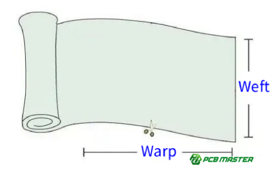
Warp direction (also called the longitudinal or machine direction) refers to the direction in which the PCB material is rolled or fed during manufacturing. This direction is typically aligned with the material's strongest mechanical properties, such as tensile strength.
Weft direction (also called the transverse or cross-direction) is perpendicular to the warp direction. It tends to have slightly different thermal expansion and mechanical properties. In most cases, the material expands more in the weft direction than in the warp direction, which can affect the PCB’s overall dimensional stability.
To present the differences between the warp and weft directions in a more structured and clear way, here’s a simple comparison table:
| Property | Warp Direction | Weft Direction |
| Also Known As | Longitudinal or Machine Direction | Transverse or Cross-Direction |
| Orientation | Aligned with the direction of material feeding during manufacturing | Perpendicular to the warp direction |
| Mechanical Properties | Typically aligned with the material's strongest mechanical properties (e.g., tensile strength) | Slightly weaker than warp, but still important for structural integrity |
| Thermal Expansion | Lower expansion compared to the weft direction | Tends to expand more than the warp direction, affecting dimensional stability |
| Effect on PCB | Less likely to cause warping during soldering or heat exposure | Can cause warping or distortion due to higher expansion under heat |
| Dimensional Stability | More stable, less prone to dimensional changes | More sensitive to thermal changes, leading to potential distortion |
For example, if a PCB is exposed to heat during soldering, the expansion in the weft direction may cause warping or distortion, which can lead to manufacturing defects.
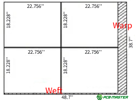
How Are PCB Size and Direction Determined (e.g., 36" × 49" Example)?
The dimensions of PCB materials (e.g., 36" × 49") are typically determined by the large base materials (such as copper-clad laminates) used in manufacturing. In these materials, the warp direction aligns with the shorter side (36 inches), while the weft direction aligns with the longer side (49 inches). This is because the PCB material is usually rolled or fed onto the production line in the warp direction.
When a designer specifies a PCB's dimensions, they must consider the impact of the material's directional properties on the final design. For example, if the PCB needs to be flexible or undergo a certain level of thermal cycling, the designer might choose to orient the warp direction in a way that minimizes thermal expansion in the most critical areas of the PCB.
Where Do the Warp and Weft Directions in FR-4 and Glass Fiber Come From?
FR-4 and glass fiber—two commonly used PCB materials—are fibrous materials that are processed in specific ways, determining their warp and weft directions.
FR-4, a composite material consisting of woven fiberglass and epoxy resin, has its warp direction influenced by the orientation of the fiberglass weave. The fiberglass strands are woven tightly together in the warp direction, providing higher strength along this axis. This makes the material stiffer and stronger in the warp direction than in the weft direction.
Glass fiber used in PCBs is typically woven into a fabric, with the warp direction aligned with the machine’s feed direction during the manufacturing process. This results in a stronger, more stable material in the warp direction, while the weft direction may have slightly more flexibility.
In practical terms, this means that the PCB’s performance, especially its mechanical strength, will vary depending on the orientation of the warp and weft directions during the design and manufacturing process. Understanding how these directions behave under stress, temperature, and moisture changes is crucial for preventing defects like warping and delamination during production.
Why Must PCB Material Direction Be Strictly Controlled?
Proper control of PCB material direction—warp and weft—is essential to maintain the reliability, dimensional stability, and mechanical strength of the final product. Even small differences in how the material expands or behaves under stress can lead to defects like warping, cracking, or poor electrical connections. By managing these directional properties throughout the PCB manufacturing process, manufacturers can ensure the long-term performance and reliability of their products.
How Do Thermal Expansion Differences Affect Reliability?
Thermal expansion refers to the way materials change in size when they are heated or cooled. In PCB materials, the warp direction (machine direction) and the weft direction (transverse direction) often have different thermal expansion rates. The weft direction typically expands more than the warp direction under heat.
For example, during high-temperature processes like soldering or reflow soldering, if the PCB material expands unevenly due to thermal expansion differences, it can cause the board to warp. This warping leads to issues like misalignment of components, cracked solder joints, and poor electrical connections. Managing this difference ensures that the PCB behaves predictably, preventing defects and enhancing the product’s reliability.
How Do Dimensional Stability and Moisture Absorption Differ?
Dimensional stability is how well a material maintains its size and shape under varying conditions, such as temperature and humidity changes. In PCB manufacturing, the warp and weft directions have different moisture absorption rates. The weft direction usually absorbs moisture at a slightly higher rate than the warp direction, which causes the material to expand and contract differently.
For example, if the PCB is exposed to moisture in a humid environment, it may swell more in the weft direction than in the warp direction, causing the board to distort. This can lead to issues like poor fit of components or difficulty during assembly. By controlling the directionality, manufacturers can reduce this risk, ensuring the PCB remains dimensionally stable even in fluctuating environmental conditions.
How Do Mechanical Strength Differences Affect the PCB?
The mechanical strength of PCB materials is not uniform in all directions. The warp direction generally has higher tensile strength (resistance to stretching) compared to the weft direction, where the material is typically more flexible. This means that a PCB is more resistant to deformation along the warp direction than the weft direction.
For instance, if the PCB is exposed to mechanical stress (such as bending or pressure during installation), the board is more likely to bend or break along the weft direction. If the warp and weft directions are not properly managed, this can lead to unpredictable performance, such as delamination (layers separating) or fractures in the PCB, especially in high-stress applications like smartphones or servers. Proper directional control ensures the PCB can withstand mechanical forces without failure.
How Do Multilayer PCB Stress Accumulation and Warping Risks Arise?
In multilayer PCBs, the stress accumulation caused by misalignment of the warp and weft directions between the different layers can result in warping. If the internal layers are not aligned with the same warp direction as the outer layers, the differences in thermal expansion and mechanical strength across layers can cause the board to warp or become uneven.
For example, in a 4-layer PCB, if the top and bottom layers are aligned in the warp direction, but the internal layers are aligned in the weft direction, the PCB may experience internal stress when exposed to heat or pressure. Over time, this can lead to deformation or warping, which makes the PCB unsuitable for high-precision applications. Controlling the warp and weft alignment during lamination and pressing reduces the risk of warping, ensuring that the PCB remains stable and functional in demanding applications.
What Key Performance Indicators Are Affected by PCB Warp and Weft Direction Differences?
The direction in which PCB materials (warp vs. weft) are aligned can significantly impact various performance metrics, such as thermal expansion, dimensional stability, mechanical strength, and high-temperature response. These differences can cause warping, stress, and misalignment during manufacturing, affecting the final product’s performance. Understanding how these factors play out in the warp and weft directions is critical to ensuring the quality of the PCB.
What Are the Differences in Coefficient of Thermal Expansion (CTE)?
Coefficient of Thermal Expansion (CTE) is the measure of how much a material expands or contracts with temperature changes. PCB materials typically have different CTEs in the warp and weft directions, which can cause uneven expansion during heating and cooling cycles. The weft direction usually has a higher CTE than the warp direction, meaning it expands more when exposed to heat.
For example, during a soldering process or reflow soldering, the PCB might warp if the material expands at different rates along the warp and weft directions. This misalignment can lead to misplaced components or poor solder joints. In precision electronics, such as smartphones or servers, where temperature fluctuations are common, managing CTE differences is critical for ensuring reliable and durable performance.
How Do Dimensional Shrinkage and Expansion Differ?
Dimensional shrinkage and expansion refer to how much a material changes in size when exposed to environmental factors like temperature and humidity. In PCB manufacturing, the warp and weft directions exhibit different shrinkage or expansion rates.
For example, when a PCB absorbs moisture or undergoes a thermal cycle, the weft direction typically experiences a higher rate of dimensional change compared to the warp direction. This leads to warping or distortion, especially in high-density interconnect (HDI) designs, where precise component placement is essential. Proper management of these dimensional changes through controlled material alignment can prevent assembly issues and improve product quality.
How Do Mechanical Strength Properties Differ?
The mechanical strength of PCB materials is not uniform across directions. The warp direction generally has higher tensile strength (resistance to stretching) compared to the weft direction. This difference is important when considering how the PCB will perform under mechanical stress.
For instance, if a PCB is bent or subjected to pressure during assembly or in end-use, the weft direction is more likely to deform or even crack, while the warp direction will be more resistant to these forces. In applications like automotive electronics, where PCBs are exposed to vibrations and mechanical stress, the mechanical strength difference must be managed to avoid PCB failure. Ensuring correct directional alignment enhances the durability and performance of the PCB.
How Do High-Temperature Processes Affect PCB Material Direction?
High-temperature processes, such as reflow soldering and wave soldering, can cause significant thermal stress on PCBs. The way the material reacts to heat depends on the warp and weft directions. As mentioned earlier, the weft direction often expands more than the warp direction, which can lead to stress accumulation or warping during high-temperature exposure.
For example, in multilayer PCBs, the thermal expansion mismatch between layers oriented in different directions can cause the PCB to warp, leading to component misalignment or failure in the final product. During high-temperature processes, such as those used in automotive or aerospace applications, managing the thermal response across warp and weft directions is essential to avoid product defects and ensure performance at high operating temperatures.
What Are the Key Control Points and Considerations for PCB Warp and Weft Direction in Manufacturing?
In PCB manufacturing, controlling the warp and weft direction of materials at various stages is essential for ensuring consistent quality and reliable performance. These control points span from the initial cutting phase to the final inspection. Properly managing the warp and weft directions throughout the process prevents defects such as warping, misalignment, and poor soldering, ensuring the product’s longevity.
How Is Warp and Weft Direction Controlled During the Cutting Process (Operational Guidelines)?
The cutting process in PCB manufacturing must be carefully controlled to maintain the proper alignment of the warp and weft directions. During this stage, directionality should be marked, tracked, and maintained to prevent errors later in the production line.
How Are Materials Cut According to Design Specifications?
PCB materials must be cut according to the design drawings, with clear specifications for warp and weft directions. The design drawing should explicitly indicate the direction for each PCB section to ensure correct alignment during the cutting process. For example, if the PCB design specifies that certain areas should be aligned with the warp direction, the operator should follow this orientation to avoid misalignment during later processes like layer lamination or soldering.
How Are AB Materials Managed (Edge Cutting/Size Differences)?
In some cases, AB materials are used, where two different PCB boards are cut from the same large sheet but require different handling due to differences in size or edge cutting. To prevent mix-ups, the materials must be clearly labeled, and their respective warp and weft orientations should be carefully maintained throughout the cutting process. This distinction helps avoid cross-contamination of boards with varying dimensions or material properties.
How Are Tools Differentiated for Each Direction?
Different tools should be used for cutting or processing depending on whether the material is aligned with the warp or weft direction. Specially calibrated tools ensure that the cutting process aligns with the required properties of the board. For example, a circular saw used for cutting should be calibrated to minimize stress in the weft direction if it's more sensitive to deformation.
What Is the Role of Process Cards in Traceability and Directional Control?
Process cards are essential for tracking the warp and weft directions throughout the production process. Each process card should include clear markings of the direction and size of the PCB materials, allowing operators to easily verify if the correct materials are being processed. This traceability helps in preventing mistakes and ensuring quality control across multiple production steps.
What Information Should Be Included on the Process Card?
Each process card should include clear directional markings (arrows, dimensions, or color codes) to identify the warp and weft orientations. This ensures that operators are always aware of the material's intended alignment, preventing potential errors from creeping into later stages like drilling or soldering.
How Is the First Piece Checked for Directional Accuracy?
The first piece in the production process (often referred to as the "first article") should undergo a thorough directional check to ensure it adheres to the design's requirements. After confirming the correct orientation, the rest of the batch can proceed. This prevents errors from propagating through the entire production run.
How Are Warp and Weft Directions Controlled During Layer Transfer and Flow to Avoid Confusion?
Maintaining directional consistency during layer transfer and flow through various PCB processes is vital to avoid misalignment that can cause defects.
How Is Directional Information Continuously Transferred on Process Cards?
The process card serves as a directional guide for each layer, ensuring that the information about the warp and weft direction is passed accurately through each step of the process. This transfer of information guarantees that the orientation remains consistent, reducing the risk of confusion and errors during subsequent operations such as exposure or developing.
What Is the Directional Consistency During Exposure and Developing?
During exposure and developing stages, it’s crucial to maintain the directional alignment of the PCB. Since these stages involve the exposure of light-sensitive material, any misalignment can result in incorrect pattern formation. Ensuring that the warp and weft directions are accurately followed at these stages prevents pattern shifting and ensures precise PCB structure.
How Is Mixing Prevented During Material Flow?
As the materials flow through various manufacturing stages, it’s essential to have controls in place to prevent mixing of materials with different warp and weft orientations. Clear labeling, physical barriers, and scheduling systems can help ensure that materials are always correctly aligned, reducing the risk of confusion and mistakes.
What Are the Standard Operating Procedures (SOPs) for Directional Control?
Standard Operating Procedures (SOPs) must be strictly followed at each step to ensure consistent orientation throughout the production process. These procedures outline how operators should manage the warp and weft directions during cutting, lamination, drilling, and other critical stages, ensuring that the final PCB aligns with the design specifications.
What Are the Key Control Points for Warp and Weft Direction in PCB Lamination?
During lamination, the alignment of warp and weft directions is crucial to ensure that the PCB maintains its shape and dimensional stability.
How Should Lamination Structure Be Designed for Directional Consistency?
The lamination structure must ensure that the warp and weft directions of all layers are aligned correctly, as discrepancies can lead to warping or delamination. All layers should be oriented with the same warp direction, or carefully designed to balance out expansion differences between layers.
How Should Core and Prepreg Layers Be Matched for Direction?
The core board and prepreg layers (which are partially cured materials) must be carefully matched in terms of direction. If the prepreg’s orientation does not match the core board's warp direction, it can lead to uneven pressure distribution during lamination, causing delamination or warping.
How Should Multilayer PCBs Be Symmetrically Designed for Stress Balance?
For multilayer PCBs, the design should ensure symmetry around the center layer to balance internal stress. This reduces the risk of warping during thermal cycles, as mismatched layers can result in uneven thermal expansion. The outer layers should align with the core layers in the correct direction to ensure stress balance during production.
What Are the Standard Steps for Laminating Layers with Correct Orientation?
The standard steps for lamination should include layer-by-layer verification of directional alignment before pressing. Operators must confirm the warp and weft directions of each layer and ensure consistency. This prevents errors that could lead to misalignment or defects in the final PCB.
What Should Be Included in the Lamination Checklist?
The lamination checklist should verify each layer's direction, material thickness, and matching with prepreg or core materials. Any deviation from the standard should be flagged immediately.
What Are Common Errors in Lamination Process?
Common errors include ignoring prepreg direction or relying on experience rather than the standard operating procedure (SOP). These errors can result in uneven lamination, causing the PCB to warp or fail under stress.
How Does Warp and Weft Direction Affect Drilling Precision?
In drilling, the warp and weft directions influence the precision of hole placements and the overall accuracy of the PCB layout.
How Does Directionality Affect Drilling Accuracy?
Drilling in different directions (warp vs. weft) can affect the precision of the holes. The material’s expansion properties may cause hole misalignment, leading to poor electrical connections or misplaced components.
How Is Shrinkage Compensation Linked to Direction?
Compensating for material shrinkage during drilling requires an understanding of the directionality of the material. If the shrinkage rate differs between the warp and weft directions, adjustments must be made in the drilling programming to ensure accurate hole sizes and placements.
What Is the Role of Drill Tape Design?
The drill tape design should consider the material's expansion properties. Based on the warp and weft differences, the drilling path and tape alignment must be adjusted to ensure the final drilled holes are perfectly aligned with the design.
What Are the Key Drilling Control Points?
Drilling control points should focus on maintaining consistent hole size, ensuring precise hole alignment, and adjusting for shrinkage differences between the directions.
How Can Final Inspection Evaluate Warp and Weft Control Effectiveness?
The final inspection evaluates how well the warp and weft directions were managed throughout production. This is crucial to ensure that the PCB meets the design specifications and will perform reliably.
How Is Warping Measured and Evaluated?
Warping can be measured by checking the flatness of the PCB using a laser or optical sensor. If the warping exceeds the tolerance limits, it indicates improper directional control during earlier stages.
How Are Dimensional Stability and Direction Evaluated?
Dimensional stability is evaluated by measuring board size before and after environmental exposure (e.g., temperature changes or humidity). Any significant changes can indicate poor directionality control.
How Are High-End Products (Servers/Communication Boards) Tested for Directional Control?
For high-end products like servers or communication boards, dimensional stability and warping are critical, as even slight misalignments can lead to performance issues. These products are often subjected to rigorous testing under high temperature and humidity conditions to evaluate how well the PCB maintains its shape and size under stress. The testing process ensures that the warp and weft directions are properly managed, providing insight into the effectiveness of the manufacturing process and overall product reliability.
How Are Abnormal Results Analyzed for Directional Issues?
If abnormal results such as warping, misalignment, or distortion are found during the final inspection, root cause analysis is performed. This involves tracing back through the manufacturing steps to identify where the warp and weft directions may have been incorrectly aligned. By reviewing process cards, layer alignment, and lamination procedures, manufacturers can determine whether issues arose due to directional mismanagement, helping prevent similar problems in future production runs.
Conclusion
Managing the warp and weft direction of PCB materials is essential to ensure the stability, reliability, and performance of the final product. By meticulously controlling directional properties through every step of the manufacturing process—from cutting and lamination to drilling and final inspection—manufacturers can prevent defects like warping, misalignment, and poor soldering, ultimately delivering high-quality PCBs that meet design specifications.
As a seasoned PCB and PCBA supplier, PCBMASTER is dedicated to providing customers with top-tier products that adhere to the highest industry standards. With years of experience and a commitment to precision, PCBMASTER ensures that every PCB we produce is reliable, durable, and ready for the most demanding applications.
FAQs
How to Quickly Identify the Warp and Weft Directions of a PCB?
Identifying the warp and weft directions of a PCB is crucial for ensuring proper alignment throughout the manufacturing process. Here are a few quick methods:
1. Check the Manufacturer's Documentation: The most reliable way is to refer to the design drawings or process cards, which typically indicate the correct orientation of the warp and weft directions.
2. Visual Indicators: Manufacturers often mark the warp direction on the PCB with arrows, labels, or dimension indicators that show the intended orientation of the material.
3. Grain Test: Lightly bending the PCB (with caution) can reveal the direction of its fibers. The warp direction will typically be stronger and less flexible than the weft direction.
4. Edge Inspection: Look for any grain patterns or manufacturing marks along the edges, as they often reflect the material’s feed direction during production.
Does Prepreg (PP) Need to Have Its Direction Distinguished?
Yes, prepreg (a semi-cured resin material used in PCB manufacturing) must have its directionality carefully managed, just like the core PCB material. The orientation of the prepreg layers plays a critical role in the lamination process and can affect the PCB's strength, thermal stability, and overall performance.
If the prepreg’s direction is not aligned properly with the core layers (in the correct warp or weft direction), it can cause issues like delamination, misalignment, or warping. It is essential to ensure that the prepreg’s fibers run in the same direction as the core material or follow a prescribed design pattern to maintain structural integrity.
At Which Stage Are Warp and Weft Direction Errors Most Likely to Appear?
Errors in warp and weft direction are most likely to be exposed during the lamination and drilling stages of PCB manufacturing. These stages involve the stacking of layers and precise hole placement, both of which are heavily influenced by the direction of the materials. If the layers are not aligned properly, it can lead to:
l Warping of the PCB during lamination due to thermal expansion mismatches.
l Misaligned holes and poor drilling accuracy if the material's directional properties were not taken into account during setup.
Furthermore, errors can be detected during visual inspections or final testing, such as checking for dimensional stability or warping after thermal exposure.
Do Single-Sided PCBs Need Directional Control?
Yes, single-sided PCBs also require directional control, albeit to a lesser extent than multi-layer boards. While single-sided PCBs have fewer layers, ensuring the correct alignment of materials is still important to prevent issues like warping or deformation.
In single-layer boards, the material's directionality affects solderability, dimensional stability, and thermal behavior. If the warp and weft directions are not properly managed, even simple processes like soldering or component placement could lead to defects. Therefore, controlling the warp and weft directions in single-sided PCBs helps maintain overall quality and reliability.
Author Bio
Hi, I'm Carol, the Overseas Marketing Manager at PCBMASTER, where I focus on expanding international markets and researching PCB and PCBA solutions. Since 2020, I've been deeply involved in helping our company collaborate with global clients, addressing their technical and production needs in the PCB and PCBA sectors. Over these years, I've gained extensive experience and developed a deeper understanding of industry trends, challenges, and technological innovations.
Outside of work, I'm passionate about writing and enjoy sharing industry insights, market developments, and practical tips through my blog. I hope my posts can help you better understand the PCB and PCBA industries and maybe even offer some valuable takeaways. Of course, if you have any thoughts or questions, feel free to leave a comment below—I'd love to hear from you and discuss further!

