


Boost FPC Bending Durability: Essential Materials and Design Strategies for Better Flexibility
With the growing demand for flexible electronic devices, the need for durable and reliable flexible printed circuit boards (FPCs) has never been greater. From smartphones to automotive electronics, FPCs are integral to a wide range of applications, where their ability to endure continuous bending and stress directly impacts performance and longevity. The global FPC market is set to experience substantial growth, with projections estimating its value at USD 23.89 billion in 2024, reaching USD 50.90 billion by 2030, growing at a CAGR of 13.7% from 2025 to 2030. This expansion is largely driven by the increasing demand for flexible electronics in various vehicles and rapid advancements in automotive technologies. As the market evolves, understanding the factors that enhance FPC Bending durability becomes essential. In the following, we'll explore the innovations that enable FPCs to withstand repeated bending and how cutting-edge materials and design strategies are shaping the future of flexible electronics.
What is the Basis of FPC's Bending Durability?
FPCs are essential in many modern electronic devices due to their ability to bend and conform to various shapes. The core of their bending durability lies in the materials used, their design, and the manufacturing processes involved. To understand this, it's important to first look at the structure of FPCs, how they differ from traditional rigid circuit boards, and the factors that affect their bending performance.
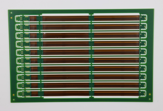
Structure and Composition of Flexible Printed Circuit Boards (FPCs)
FPCs are made up of flexible base materials like polyimide (PI) or polyester (PET), which are combined with copper conductors to form electrical circuits. These boards are thinner and more flexible than traditional rigid boards, which allows them to bend without breaking. The copper is usually bonded to the flexible substrate using an adhesive or in a non-adhesive configuration for improved durability. FPCs often have multiple layers, allowing them to carry complex circuitry in a compact space.
For example, in smartphones, FPCs are used to connect various components like the screen, battery, and processor. Their ability to bend without damage makes them ideal for devices with limited space or those requiring flexible connections.
How Do FPCs Differ from Traditional Rigid Circuit Boards?
The key difference between FPCs and traditional rigid circuit boards lies in flexibility. Rigid circuit boards, made from materials like fiberglass, are designed to stay flat and do not bend. While they offer durability and strength, they cannot be used in applications requiring flexibility or bending. On the other hand, FPCs are designed for applications that demand flexibility, such as wearable devices, flexible screens, and automotive electronics.
In a real-world example, a traditional rigid circuit board might be used in a desktop computer, where the components are fixed and don’t require bending. However, an FPC would be used in a smartwatch or fitness tracker, where the circuit needs to conform to the curved shape of the wrist and withstand continuous bending.
What Are the Factors Affecting FPC's Bending Durability?
Several factors influence the bending durability of FPCs, including the materials chosen, the design of the circuit, the manufacturing process, and the environmental conditions to which the FPC will be exposed.
Material Selection: The base materials (such as polyimide or PET) and the type of copper used in the circuit (e.g., rolled annealed copper for better flexibility) play a significant role in how well an FPC can handle repeated bending.
Design: The layout of the circuit, including the direction of the traces and the use of smooth, gradual bends, can reduce the stress on the board when it is bent.
Manufacturing Process: Processes like lamination, etching, and coating affect the final flexibility and durability of the FPC. For example, non-adhesive copper bonding tends to increase durability compared to traditional adhesive methods.
Environmental Factors: Exposure to high temperatures, humidity, and mechanical stress can impact the performance of FPCs over time, causing materials to degrade or fail.
These factors will be explored further in the following sections, where we delve into material choices, design strategies, and manufacturing processes that help improve the bending durability of FPCs.
How Can the Durability of FPCs Be Optimized Through Material Selection?
The materials chosen for FPCs are critical in ensuring their durability and ability to withstand repeated bending. The right combination of base material, copper foil, and adhesive can significantly improve the bending performance of FPCs. Below, we will explore how to choose the appropriate materials for FPCs, the role of copper foil, and the importance of adhesives in enhancing bendability.
How to Choose the Right Substrate Material?
The choice of substrate material is essential for optimizing the bending durability of FPCs. The most commonly used substrate is polyimide (PI), which is favored for its excellent flexibility and resistance to high temperatures. However, there are other materials, like polyester (PET), which may be more suitable for specific applications but tend to have lower flexibility and thermal resistance compared to PI.
Polyimide vs. Other Materials: Polyimide is known for its superior flexibility, thermal stability, and resistance to chemicals. It can withstand temperatures ranging from -269°C to 400°C, making it ideal for environments with fluctuating temperatures. In contrast, materials like polyester are cheaper but may not provide the same level of durability under stress.
Dynamic vs. Static Bending Materials: For dynamic bending (repeated bending during the product's use), thinner PI materials such as 0.5mil or 1mil (mil = thousandths of an inch) are often used. These thinner materials allow for greater flexibility and are suitable for applications like flexible sensors or wearable devices, where continuous movement is common. For static bending (where the material is bent once or a few times), thicker PI materials can be used, as the material does not need to endure continuous stress.
In a practical example, a smartphone might use thinner polyimide in the flexible connectors inside, while a vehicle dashboard might use a thicker polyimide for a static display that won't bend repeatedly.
The Role of Copper Foil in Bending Durability
Copper foil is a crucial element in the construction of FPCs, as it carries the electrical current through the circuit. The type of copper foil used affects the board’s ability to endure bending stresses.
Electrolytic Copper vs. Rolled Annealed Copper: Electrolytic copper is commonly used in standard circuit boards, but it has a columnar crystal structure, which makes it less flexible. Rolled annealed copper (RA copper), on the other hand, has a lamellar (layered) crystal structure, which allows it to bend and stretch much more effectively without cracking or breaking. This makes RA copper the preferred choice for FPCs that need to withstand dynamic bending, such as in smartwatches or flexible displays.
RA Copper’s Advantage in Dynamic Bending: RA copper’s flexible structure is ideal for dynamic bending applications where the circuit board experiences repeated flexing, like in foldable smartphones. The material can flex and return to its original shape without suffering damage, significantly extending the lifespan of the device.
For instance, in a mechanical arm used in robotics, RA copper would be critical for the internal circuits that bend frequently as the arm moves.
Adhesive Selection: Why Are Non-Adhesive Substrates Better for Bending Durability?
The type of adhesive used in FPCs also plays a significant role in their bending durability. Traditional adhesives, such as acrylic or epoxy resins, can degrade or crack over time when subjected to repeated bending.
The Disadvantages of Traditional Adhesives: Acrylic and epoxy adhesives can become brittle and lose their adhesive strength after repeated bending, leading to failures in the circuit. This is especially problematic in dynamic bending applications where the adhesive is subjected to constant stress.
The Benefits of Non-Adhesive Substrates: Non-adhesive FPCs, where copper is directly bonded to the polyimide substrate without the use of adhesives, offer significantly better durability. This type of construction removes the potential failure point that adhesives introduce, resulting in a more robust and flexible board. Non-adhesive copper bonding directly to the polyimide is preferred in high-end applications like flexible sensors or wearable devices, where long-term reliability is essential.
In a real-world example, a smartphone's internal circuits are often designed with non-adhesive copper bonding to ensure that the device remains durable even under constant use and bending.
How Can FPC Bending Durability Be Optimized Through Circuit Design?
The design of the electrical circuits on FPCs plays a key role in their ability to withstand bending and stress. By optimizing the layout and structure of the circuit, it is possible to minimize the risk of failure due to repeated bending. Below, we will discuss the importance of defining bending areas, the relationship between circuit routing and bending axes, and the best practices for line width and spacing.
How to Design the Bending Area Effectively?
Defining and isolating bending areas is critical in optimizing FPC durability. A bending area is a region of the circuit that will be subjected to frequent or continuous bending during the product’s use. Properly marking and isolating these areas helps in making design decisions that reduce stress and avoid damage.
Importance of Isolating Bending Areas: By clearly marking the bending areas on the design schematic, designers can avoid placing sensitive components in these zones. This ensures that parts of the circuit that are most likely to experience stress—like connectors, components, and solder pads—are not placed in areas prone to bending, which reduces the risk of failure.
Avoiding Placement of Components and Pads in Bending Zones: Components, connectors, and solder pads should be avoided in the bending area. These parts are more vulnerable to damage when bent frequently. For example, placing a capacitor or resistor directly in a bending zone could cause it to crack or fail over time due to the mechanical stress.
A real-life example would be in wearable devices, where flexible circuits are often used on straps or screens. Designers carefully plan to place components away from areas where the band or screen might frequently bend, ensuring the circuits remain functional over time.
What Are the Best Practices for Routing Circuit Traces?
The routing of circuit traces, or "wires", is crucial to ensuring that the FPC can bend without damaging the electrical connections. Understanding the relationship between the trace layout and the bending axis is essential.
Relationship Between Trace Direction and Bending Axis: To optimize for bending, circuit traces should be routed perpendicular to the bending axis. When traces are aligned parallel to the bending axis, bending can cause the traces to stretch and break, leading to failures. By routing traces perpendicular to the bend, stress is more evenly distributed across the circuit, minimizing the risk of damage.
Advantages of Using Arc Transitions and Tear-drop Pads: Using arc-shaped transitions between traces rather than sharp angles helps distribute stress more evenly. Sharp corners can concentrate stress, leading to potential failures. Additionally, using tear-drop pads—pads that have a smooth, rounded shape—helps avoid stress concentration at the pad edges, improving durability. This design technique is especially useful in dynamic bending applications, such as flexible sensors or bendable electronics.
In practice, if designing a flexible display or foldable phone, using smooth, arc-shaped transitions and avoiding sharp corners can significantly improve the lifespan of the flexible circuits.
How to Optimize Trace Width and Spacing for Better Durability?
Trace width and spacing are critical factors in ensuring that the FPC can withstand repeated bending. Optimizing these parameters reduces stress and prevents failures that can occur when the traces become too narrow or too close together.
Maintaining Consistent Trace Width: Consistency in trace width is important to ensure that the circuit behaves predictably when it bends. Varying trace widths can lead to areas of increased stress, which might cause the circuit to break. Therefore, uniform trace width across the bending area ensures that the stress is distributed evenly and minimizes the risk of breakage.
Why Wider Spacing Helps Reduce Stress: Wider spacing between traces, especially in bending areas, allows for more room for the circuit to expand and contract as it bends. This prevents the traces from being too tightly packed, which can increase stress and result in failure. For example, in high-flex applications like wearable devices or foldable smartphones, increasing the trace spacing in areas subject to frequent bending can extend the product's life.
In summary, by ensuring consistent trace width and appropriate spacing, designers can create more durable FPCs capable of withstanding the mechanical stress of continuous bending. For example, when designing flexible circuit boards for medical devices, it’s critical to maintain wider trace spacing to ensure long-term functionality and reliability.
How Can FPC Bending Durability Be Controlled Through Manufacturing Processes?
The manufacturing process of FPCs plays a crucial role in ensuring their durability and bending performance. By controlling factors like lamination precision, protective layers, and etching quality, manufacturers can optimize the FPCs' ability to withstand repeated bending without failure. Let's explore the key manufacturing techniques that impact FPC bending durability.
How to Control Lamination Precision?
Lamination is a critical process in FPC production, where different layers of the flexible substrate are bonded together. Precision during lamination is essential to avoid defects such as air bubbles, delamination (layer separation), and uneven adhesive layers.
Avoiding Air Bubbles and Delamination: During lamination, air bubbles or trapped gases between the layers can create weak points in the FPC, making it more susceptible to bending failures. To prevent this, manufacturers use high-quality laminating machines that apply uniform pressure and heat, ensuring proper bonding between layers. Special care must be taken to control temperature and pressure during the lamination process to avoid these defects.
Ensuring Even Adhesive Layer Thickness: Uneven adhesive layers can lead to delamination or areas of high stress concentration. By using precise equipment that evenly distributes the adhesive material, manufacturers ensure a consistent bond between layers. This helps prevent weak spots and maintains the FPC's flexibility and durability under bending stress.
For example, in wearable devices or flexible screens, lamination precision is crucial to avoid gaps or uneven bonding, which can cause the circuit to fail prematurely during regular use.
The Role of Covering Films and Protective Layers
Covering films and protective layers are applied to FPCs to provide an additional level of protection against mechanical stress, environmental factors, and electrical interference. These layers play a crucial role in ensuring the durability of the FPC during bending cycles.
Choosing Polyimide Cover Films: Polyimide (PI) is the preferred material for covering films due to its excellent flexibility, thermal stability, and resistance to mechanical wear. PI films protect the underlying copper traces and help the FPC withstand repeated bending without breaking down. Other materials may be used, but PI films offer the best combination of performance and reliability.
Ensuring Full Coverage and Protection: It's not enough to just apply a covering film; it must cover the entire surface of the FPC, including sensitive areas like the copper traces. The protective layer must be applied evenly, without gaps or inconsistencies, to fully protect the FPC. Any exposed areas are vulnerable to damage and could fail under repeated bending. Additionally, manufacturers should ensure that the protective layer is thick enough in areas that will experience more stress, such as the bending zones.
For instance, in flexible electronics used in automotive or medical applications, full coverage of the FPC with a durable polyimide layer helps prevent wear and tear, ensuring the circuits remain functional even under harsh conditions.
What Are the Requirements for Etching Process Quality?
Etching is the process of removing unwanted copper from the FPC to create the desired circuit pattern. The quality of the etching process is essential for ensuring the durability of the FPC, particularly in reducing stress points that could cause failure during bending.
Smooth Trace Sidewalls and Their Role in Stress Reduction: Etching should produce smooth, uniform sidewalls on the copper traces. Rough or uneven edges can create weak points where stress concentrates, increasing the risk of cracks or failures when the FPC is bent. High-quality etching ensures that the sidewalls of the traces are smooth, which helps distribute stress more evenly across the circuit.
Reducing Stress Concentration: Sharp corners or uneven trace paths can concentrate stress, leading to possible damage. By using precise etching techniques that create smooth, rounded corners and consistent trace widths, manufacturers reduce the risk of stress concentrations. This is particularly important in dynamic bending applications, where the FPC is subjected to continuous flexing, such as in flexible displays or robotic arms.
In practical terms, a smartphone screen uses high-quality etching to ensure the internal flexible circuits remain intact and functional even with frequent folding and unfolding.
How Do Environmental Conditions Affect the Bending Durability of FPCs?
FPCs are highly sensitive to environmental conditions. Factors like temperature, humidity, chemical exposure, and mechanical vibrations can all impact the performance and longevity of FPCs. Understanding these influences is critical to designing FPCs that can withstand harsh environments and prolonged use.
How Do High Temperature and Humidity Affect FPCs?
Temperature and humidity fluctuations can significantly affect the materials used in FPCs, potentially compromising their bending durability and functionality over time.
Impact of Temperature and Humidity on Material Stability: FPCs are made from flexible substrates like polyimide (PI) and copper, which have specific temperature and humidity tolerances. High temperatures can cause the substrate to soften or degrade, while low temperatures can make it more brittle. Humidity, on the other hand, can lead to material expansion or contraction, affecting the copper traces and causing potential delamination (separation of layers). These changes can lead to poor performance or failure, especially in environments with frequent temperature shifts or high humidity.
For example, in automotive electronics, where FPCs are used in dashboards or control systems, extreme temperatures can lead to cracking or short-circuiting if the FPC is not designed to handle these conditions.
How to Mitigate Effects: To combat the effects of temperature and humidity, FPCs are often coated with protective films, like polyimide, which can withstand extreme temperatures. Additionally, designers may use moisture-resistant coatings or encapsulation to protect sensitive components.
How Do Chemical Exposure and Mechanical Vibrations Impact FPCs in the Long Term?
In addition to temperature and humidity, chemical exposure and mechanical vibrations are other critical factors that influence the durability of FPCs.
Long-Term Effects of Chemical Exposure: FPCs used in environments where they come into contact with chemicals—such as cleaning agents or oils—can experience degradation of their protective layers, solder joints, or copper traces. For example, exposure to acidic or alkaline substances can corrode the copper, weakening the circuit. Over time, chemical exposure can cause delamination, trace cracking, or even total circuit failure.
In medical devices or industrial machinery, where FPCs might be exposed to chemicals regularly, selecting corrosion-resistant materials and coatings is vital to ensure long-term reliability. Fluoropolymer coatings are often used to protect FPCs from chemical exposure, as they offer excellent chemical resistance.
Impact of Mechanical Vibration on FPCs: Mechanical vibrations, whether from moving parts in machinery or in vehicles, can lead to stress on the FPCs. Over time, this constant motion can cause components or solder joints to fatigue and crack. In robotic arms or automotive sensors, which experience constant vibrations, careful design and material selection are required to prevent these vibrations from causing premature failure. Manufacturers often use reinforced materials and vibration-damping designs to increase durability in such environments.
For instance, in military or aerospace applications, where FPCs are exposed to high vibration levels, specialized techniques like using soft soldering and vibration-resistant materials ensure that the circuits remain intact during long-term usage.

What Are the Methods for Reliability Testing of FPC Bending Durability?
To ensure the bending durability of FPCs, manufacturers conduct various reliability tests. These tests help evaluate how well an FPC can withstand repeated bending and environmental stresses over time. Below are key testing methods used to assess the bending performance and long-term reliability of FPCs.
What is Bending Fatigue Testing?
Bending fatigue testing simulates the repetitive bending that an FPC will undergo during its lifetime. This type of test is essential for determining how many bending cycles the FPC can endure before failing.
Standards for Bending Fatigue Testing (e.g., IPC-2223, IPC-TM-650): Reliable standards like IPC-2223 and IPC-TM-650 are commonly used to guide the testing process. IPC-2223 sets the guidelines for flexible circuit design, while IPC-TM-650 provides detailed procedures for various testing methods, including bending fatigue. These standards define the specific conditions, such as the radius of bending, the number of cycles, and the speed of bending, to ensure consistent and accurate results.
How the Test is Conducted: In a typical bending fatigue test, the FPC is repeatedly bent at a fixed radius, often thousands of times. The test measures when the circuit begins to show signs of failure, such as cracked copper traces or broken solder joints. This helps to determine the board's overall durability in real-world applications.
For example, in smartphone displays or wearable electronics, bending fatigue testing ensures the internal circuits remain intact despite regular folding or bending.
What is Microsection Analysis?
Microsection analysis is a technique used to inspect the internal structure of FPCs at a microscopic level. This method is crucial for identifying defects like cracks or delamination within the copper foil or between layers of the circuit.
How Microsection Analysis Identifies Copper Foil Cracking and Delamination: During microsection analysis, a thin slice of the FPC is cut and examined under a microscope. This allows engineers to look at the integrity of copper traces, bonding layers, and any cracks that may have formed due to bending. Delamination, which occurs when the layers of the FPC start to separate, is also detectable during this process.
Why It’s Important: Microsection analysis helps identify hidden weaknesses that may not be visible to the naked eye. This is important for early detection of potential failure points, allowing designers to improve the structure or materials of the FPC to prevent future issues.
In automotive applications, microsection analysis can detect any early-stage failures in the FPCs used for car sensors, ensuring the longevity and reliability of the vehicle's electronic systems.
What Are Environmental and Mechanical Stress Tests?
Environmental and mechanical stress testing evaluates how FPCs perform under extreme environmental conditions, including temperature fluctuations, humidity, and mechanical vibrations. These tests are critical to understanding how FPCs will react to real-world operating environments.
Thermal Cycling and Temperature-Humidity Cycling Tests: These tests subject the FPC to rapid temperature changes and high levels of humidity to simulate the environmental stresses it may face. Thermal cycling involves repeatedly heating and cooling the FPC, while temperature-humidity cycling combines both heat and moisture exposure. These tests assess the FPC’s ability to maintain its electrical properties and structural integrity despite changes in temperature and moisture levels.
Why These Tests Matter: Environmental tests help determine how an FPC will perform in harsh climates or changing environments, such as those found in outdoor electronics or medical devices. These tests can simulate conditions like extreme heat in automotive electronics or high humidity in marine applications, where FPCs are exposed to these factors regularly.
For example, FPCs used in aerospace applications undergo thermal cycling tests to ensure they remain functional despite extreme temperature shifts during flight.
Conclusion
Optimizing the bending durability of FPCs requires a balanced approach, focusing on material selection, circuit design, and manufacturing processes. Choosing flexible materials like polyimide and rolled annealed copper, designing stress-resistant circuits, and ensuring precise manufacturing techniques are all essential for durability.
In real-world applications, such as wearable devices or automotive electronics, balancing these factors ensures the FPC performs well under bending and environmental stress.
As a trusted PCB supplier, PCBMASTER provides high-quality FPCs that meet these standards, ensuring long-lasting, flexible circuits for a variety of demanding applications.
FAQs
Why Is Bending Durability Important for FPCs?
Bending durability is crucial for FPCs because they are designed to bend repeatedly in applications like wearables, foldable phones, and automotive electronics. If an FPC lacks sufficient bending resistance, it can fail prematurely, causing cracks or disconnections, ultimately reducing the product’s lifespan and reliability.
How Can Material Selection Improve FPC Bending Durability?
Choosing the right materials significantly enhances FPC durability. Polyimide (PI) is often used for its flexibility and heat resistance. Rolled Annealed Copper (RA copper) offers superior fatigue resistance, making it ideal for dynamic bending. Non-adhesive substrates, where copper is directly bonded to PI, avoid the weaknesses of traditional adhesives, which can degrade under repeated bending.
How Can FPC Design Prevent Bending Failures?
Design choices, like isolating bending areas and placing sensitive components away from these zones, are key to avoiding failures. Trace directions should be perpendicular to the bending axis, and smooth arc transitions should replace sharp corners to reduce stress. Larger bending radii (10-30 times the board thickness) help distribute stress evenly, improving durability.
What Are the Key Methods for Bending Fatigue Testing?
Bending fatigue tests, guided by standards like IPC-2223 and IPC-TM-650, simulate repeated bending to measure the FPC’s durability. The test involves bending the FPC at a set radius for thousands of cycles, assessing when it fails, such as when traces crack or delaminate.
How Do Environmental Factors Affect FPC Durability?
Environmental conditions like temperature, humidity, and vibration can weaken FPCs. Extreme temperature fluctuations can cause materials to expand or contract, while high humidity may lead to delamination. Vibrations from devices like robotics or automotive sensors can also cause fatigue. To withstand these, FPCs need moisture-resistant coatings and vibration-damping designs.
Author Bio
Hi, I'm Carol, the Overseas Marketing Manager at PCBMASTER, where I focus on expanding international markets and researching PCB and PCBA solutions. Since 2020, I've been deeply involved in helping our company collaborate with global clients, addressing their technical and production needs in the PCB and PCBA sectors. Over these years, I've gained extensive experience and developed a deeper understanding of industry trends, challenges, and technological innovations.
Outside of work, I'm passionate about writing and enjoy sharing industry insights, market developments, and practical tips through my blog. I hope my posts can help you better understand the PCB and PCBA industries and maybe even offer some valuable takeaways. Of course, if you have any thoughts or questions, feel free to leave a comment below—I'd love to hear from you and discuss further!

