








What Is a Resistor? A Complete Guide to Resistance, Types, Functions, and PCB Applications
A resistor is a passive electronic component designed to provide a specific amount of electrical resistance in a circuit. By limiting current, creating voltage drops, setting bias conditions, and controlling signal levels, resistors are fundamental to virtually every electronic system. Understanding how resistance works, how resistor values are selected, and how resistors are integrated into PCB designs is essential for engineers, designers, and electronics manufacturers.
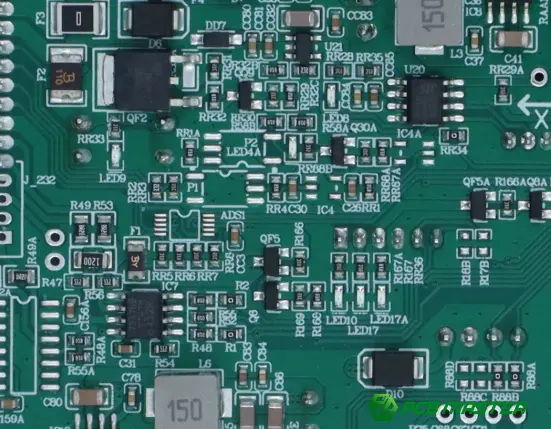
What Is a Resistor?
A resistor is a passive electronic component that opposes the flow of electric current. Its primary electrical characteristic is resistance , measured in ohms (Ω).
When voltage is applied across a resistor, the resistor limits the amount of current that can flow through the circuit. The relationship between voltage, current, and resistance is described by Ohm's law :
I=V/R
Where:
- I = current in amperes (A)
- V = voltage in volts (V)
- R = resistance in ohms (Ω)
For example, if a 10 V source is connected to a 1 kΩ resistor, the current through the resistor is:
I= 10V / 1000Ω=10mA
This simple relationship explains one of the most important functions of a resistor: controlling current according to the requirements of the circuit .
Resistors are found in power supplies, control circuits, communication equipment, automotive electronics, consumer devices, industrial systems, sensors, and virtually every category of PCB-based electronic product.
How Does a Resistor Work?
A resistor works by converting part of the electrical energy supplied to a circuit into heat .
The physical resistance of a conductive material depends on several factors, including its resistivity, length, and cross-sectional area:
R=ρL / A
A longer conductive path generally produces greater resistance, while a larger cross-sectional area generally reduces resistance.
Commercial resistors are engineered with specific resistive materials and structures to achieve a defined resistance value and power rating.
The resistor's electrical behavior can therefore be understood through three fundamental parameters:
| Parameter | Meaning | Typical Unit |
|---|---|---|
| Resistance | Opposition to current flow | Ω |
| Power rating | Maximum power the resistor can dissipate safely | W |
| Tolerance | Permitted deviation from the nominal resistance | % |
For PCB designers, these parameters must be considered together. Selecting a resistor based only on its resistance value can result in an electrically functional but unreliable design if its power rating, tolerance, package size, or environmental requirements are unsuitable.
What Are the Main Functions of a Resistor?
Although resistors are simple components, they perform many different functions in electronic circuits.
1. Current Limiting
One of the most common applications is limiting current.
For example, an LED typically requires a resistor to prevent excessive current from damaging the device. The resistor is selected according to the supply voltage, LED forward voltage, and desired operating current.
2. Voltage Division
Two or more resistors can create a controlled voltage from a higher input voltage.
For two resistors connected in series, the output voltage across one resistor can be expressed as:
Vₒᵤₜ = Vᵢₙ [ R₂ /(R₁ +R₂ ) ]
Voltage dividers are frequently used for:
- Sensor interfaces
- Analog inputs
- Feedback networks
- Reference circuits
- Microcontroller voltage monitoring
3. Biasing Active Components
Resistors are commonly used to establish appropriate operating conditions for transistors, amplifiers, and other semiconductor devices.
A carefully selected resistor network can determine the voltage or current required for a component to operate within its intended region.
4. Pull-Up and Pull-Down Functions
Digital circuits often use pull-up or pull-down resistors to establish a defined logic state when an input is otherwise floating.
These resistors are particularly common around:
- Microcontrollers
- Digital logic
- Communication interfaces
- Switch inputs
- Open-drain or open-collector circuits
5. Signal Termination
Resistors can also be used for signal termination and impedance matching.
This becomes increasingly important as signal frequencies and edge rates increase. Poor termination can contribute to reflections, ringing, overshoot, and other signal-integrity problems.
6. Current Sensing
A low-value resistor can be used as a current-sense resistor .
Because the voltage across the resistor is related to the current flowing through it, a circuit can measure this voltage and determine the current.
For precision applications, resistor tolerance and temperature coefficient become particularly important.
7. Power Dissipation
Some resistors are deliberately used to dissipate electrical power.
In such applications, the resistor must be selected with an appropriate power rating. A resistor that exceeds its rated power can experience excessive temperature rise, permanent value drift, or failure.
What Are the Different Types of Resistors?
Resistors can be classified according to construction, adjustment mechanism, package type, and application.
Fixed Resistors
A fixed resistor has a predetermined resistance value.
Common examples include:
- Thick-film resistors
- Thin-film resistors
- Metal-film resistors
- Carbon-film resistors
- Wirewound resistors
Fixed resistors are extensively used in PCB assemblies because their values remain stable under specified operating conditions.
Variable Resistors
A variable resistor allows its resistance to be adjusted.
Common types include:
- Potentiometers
- Trimmers
- Rheostats
They can be used for adjustment, calibration, user controls, and circuit tuning.
Thermistors
Thermistors are resistive components whose resistance changes significantly with temperature.
Two common categories are:
- NTC: resistance decreases as temperature increases
- PTC: resistance increases as temperature increases
They are used for temperature sensing, compensation, and protection.
Photoresistors
A photoresistor, or LDR, changes resistance according to the intensity of incident light.
It can be used in light-detection circuits and automatic lighting systems.
What Do Resistor Color Codes Mean?
Traditional through-hole resistors often use colored bands to indicate their electrical characteristics.
A typical resistor may have bands representing:
- First significant digit
- Second significant digit
- Multiplier
- Tolerance
For example, the color bands can indicate both the nominal resistance and its tolerance.
However, many surface-mount resistors (SMD resistors) do not use traditional color bands. Instead, their values may be represented using printed numerical or alphanumeric codes, depending on the component size and manufacturer.
For PCB assembly, the component's BOM, component specification, package designation, and placement data should be verified rather than relying solely on visual identification.
What Is Resistor Tolerance?
Resistor tolerance describes how much the actual resistance may differ from its nominal value.
For example, a resistor specified as:
1 kΩ ±5%
may have an actual resistance within the specified tolerance range around 1 kΩ.
Tolerance becomes especially important in:
- Precision analog circuits
- Measurement equipment
- Feedback networks
- ADC circuits
- Sensor interfaces
- Timing circuits
For high-precision applications, designers may require tighter-tolerance resistors such as ±1% or better , depending on the circuit requirements.
What Is Resistor Power Rating?
A resistor's power rating specifies how much electrical power it can dissipate under defined conditions without exceeding its permitted operating temperature.
The power dissipated by a resistor can be calculated using:
P= VI
It can also be expressed as:
P= I²R
or:
P=V²/R
This parameter is critical in PCB design.
For instance, a resistor carrying significant current may require a higher power rating even when its resistance value itself is correct.
Choosing the correct resistance value is only part of resistor selection. The designer must also evaluate power dissipation, package characteristics, tolerance, temperature coefficient, and operating environment.
What Are SMD Resistors and Through-Hole Resistors?
From a PCB manufacturing perspective, resistors are commonly divided into surface-mount devices (SMD) and through-hole components .
| Characteristic | SMD Resistor | Through-Hole Resistor |
|---|---|---|
| PCB mounting | Mounted directly on PCB pads | Leads inserted through PCB holes |
| Size | Generally compact | Generally larger |
| Assembly | Well suited to automated SMT | Often requires through-hole processes |
| Component density | High | Lower |
| Typical applications | Modern compact electronics | Power, mechanical, legacy and specialized designs |
| PCB space | Efficient | Requires additional board area |
SMD resistors are particularly important in modern SMT assembly , where automated placement enables high component density and efficient production.
How Are Resistors Used on a PCB?
A resistor is electrically simple, but its PCB implementation requires careful consideration.
Pad and Footprint Design
The PCB footprint must correspond to the resistor's package.
For an SMD resistor, important considerations include:
- Package size
- Pad dimensions
- Pad spacing
- Component height
- Solderability
- Assembly process
An inappropriate footprint can contribute to soldering defects, tombstoning, poor solder joints, or assembly difficulties.
Thermal Considerations
Power-dissipating resistors can generate significant heat.
PCB designers may need to consider:
- Copper area
- Thermal paths
- Component spacing
- Adjacent component temperature
- Enclosure conditions
Electrical Considerations
For higher-speed circuits, resistor placement can become part of the overall signal-integrity strategy.
The distance between the resistor and the relevant device, trace geometry, return path, and impedance characteristics can influence circuit behavior.
Manufacturability
A resistor may be electrically appropriate but still create manufacturing challenges if its package, footprint, placement, or soldering requirements are poorly defined.
This is why design verification and DFM review should occur before PCB production .
Common Resistor Selection Mistakes
Mistake 1: Selecting Only by Resistance
A designer may select the correct resistance but overlook power rating or tolerance.
Better approach: Evaluate resistance, tolerance, power, temperature coefficient, package, and application requirements together.
Mistake 2: Ignoring Power Dissipation
A resistor operating beyond its rated power can overheat and eventually fail.
Better approach: Calculate expected power dissipation and provide an appropriate safety margin.
Mistake 3: Using the Wrong Package
A resistor with the correct electrical value can still be unsuitable if its package does not match the PCB footprint or assembly process.
Better approach: Verify the manufacturer's package dimensions against the PCB land pattern.
Mistake 4: Treating All Resistors as Electrically Equivalent
Two resistors with the same nominal resistance can behave differently due to differences in tolerance, temperature coefficient, voltage coefficient, construction, and power characteristics.
Better approach: Select the component according to the actual electrical and environmental requirements of the application.
Resistors in Series vs. Parallel
Resistors can be combined to obtain a desired equivalent resistance.
Resistors in Series
For resistors connected in series:
Rₜₒₜₐₗ =R₁+R₂+…
The total resistance is therefore greater than any individual resistor in the network.
Resistors in Parallel
For resistors connected in parallel:
1/Rₜₒₜₐₗ = 1/R₁+1/R₂+…
The equivalent resistance is lower than the smallest individual resistance.
This technique can be useful when a specific resistance value is unavailable or when power dissipation needs to be distributed across multiple components.
What Should PCB Designers Check Before Manufacturing?
A resistor-related PCB design review should go beyond simply checking whether the resistor symbol exists in the schematic.
A practical checklist includes:
- Resistance value
- Tolerance
- Power rating
- Temperature coefficient
- Voltage rating
- Package size
- PCB footprint
- BOM accuracy
- Component availability
- Placement orientation
- Soldering requirements
- Thermal environment
- Electrical performance
- DFM compatibility
For production projects, engineering review can identify potential problems before they become manufacturing defects or costly design iterations.
Resistor Selection: Common Standards vs. Professional PCB Manufacturing Practice
| Dimension | Basic Selection Approach | Professional PCB/PCBA Practice |
|---|---|---|
| Resistance | Select nominal Ω value | Verify value against complete circuit requirements |
| Tolerance | Consider nominal tolerance | Match tolerance to circuit accuracy |
| Power | Check nominal power | Evaluate actual dissipation and thermal conditions |
| Package | Select based on size | Verify package, footprint, placement, and assembly |
| Manufacturing | Focus on schematic | Include DFM and production considerations |
| Quality | Check component specification | Verify component and finished PCB/PCBA quality |
| Production | Treat prototype and production similarly | Optimize design for prototype and mass production |
The key difference is that resistor selection should be treated as part of the complete electronic manufacturing process rather than as an isolated component-selection task.
Practical Resistor Selection Workflow
A reliable workflow can be divided into seven steps.
Step 1: Determine the Required Resistance
Calculate the required resistance based on circuit voltage, current, bias, sensing, or signal requirements.
Step 2: Determine Tolerance
Identify how much resistance variation the circuit can tolerate.
Step 3: Calculate Power Dissipation
Determine the expected operating power and select an appropriate resistor rating.
Step 4: Evaluate the Operating Environment
Consider:
- Temperature
- Humidity
- Mechanical stress
- Voltage
- Current
- Long-term reliability
Step 5: Select the Package
Choose an appropriate SMD or through-hole package according to the PCB and assembly requirements.
Step 6: Verify the PCB Footprint
Check the component manufacturer's dimensions against the PCB land pattern.
Step 7: Conduct Engineering and DFM Review
Before manufacturing, verify that the resistor selection, footprint, BOM, placement, and assembly requirements are mutually compatible.
PCBMASTER's PCB and PCBA Manufacturing Perspective
As a PCB and PCBA manufacturer serving applications across different industries, PCBMASTER treats component selection and PCB manufacturability as interconnected engineering considerations rather than isolated steps.
Its manufacturing and engineering services cover PCB, PCBA, and SMT , with capabilities including quick-turn PCB prototypes, high-frequency PCB, HDI PCB, FPC, rigid-flex PCB, and metal-core PCB.
For customers preparing a resistor-based PCB design for production, engineering file checking can help identify potential manufacturing issues before fabrication. PCBMASTER provides free engineering file review , allowing technical teams to examine manufacturability, PCB performance, and cost-effectiveness before production.
The company's quality system is supported by ISO 9001, IATF 16949, UL Certification, and RoHS compliance , while its own manufacturing facility provides integrated PCB and PCBA production capabilities.
Why Resistors Remain Fundamental to Modern Electronics
Despite their simple construction, resistors remain indispensable because almost every electronic circuit needs some form of current control, voltage control, biasing, sensing, termination, or power management .
As electronic systems become more compact and electrically complex, resistor selection increasingly involves more than choosing an ohmic value. Designers must consider electrical characteristics, thermal behavior, package dimensions, signal integrity, component availability, PCB layout, and manufacturing requirements .
For prototypes, selecting the correct resistor can prevent unnecessary redesigns. For mass production, proper component and footprint selection can also improve assembly consistency and manufacturing efficiency.
Conclusion
A resistor is a passive electronic component that controls current by providing electrical resistance . Its fundamental role is simple, but its applications range from LED current limiting and voltage division to signal termination, current sensing, biasing, and power dissipation.
For PCB designers, choosing the correct resistor requires consideration of resistance, tolerance, power rating, voltage rating, temperature characteristics, package, footprint, and manufacturability .
The most effective approach is therefore to evaluate the resistor as part of the complete PCB and PCBA system—not simply as an individual component in a schematic. Proper engineering review and DFM verification can help ensure that the selected resistor performs as intended while remaining suitable for reliable PCB assembly and production.
Frequently Asked Questions
What is a resistor?
A resistor is a passive electronic component that provides electrical resistance and limits or controls current flow in an electronic circuit.
What is the unit of resistance?
The SI unit of electrical resistance is the ohm (Ω) .
What does a resistor do in a circuit?
A resistor can limit current, divide voltage, establish bias conditions, provide signal termination, sense current, and dissipate electrical power.
What is the difference between an SMD resistor and a through-hole resistor?
An SMD resistor is mounted directly onto PCB pads, while a through-hole resistor has leads inserted through holes in the PCB. SMD resistors are widely used in automated SMT assembly and high-density PCB designs.
How do I choose the right resistor?
Start with the required resistance value, then evaluate tolerance, power rating, voltage rating, temperature coefficient, package size, footprint, operating environment, and manufacturing requirements .
Tags: #Resistor #WhatIsAResistor #ResistorBasics #Electronics #PCB #PCBA #SMT #PCBDesign #ElectronicComponents #CircuitDesign #PCBManufacturing #PCBMASTER #IndustryInsights
About the Author

Carol Luo
PCB Design EngineerI'm Carol, a PCB Engineer at PCBMASTER with experience in PCB design and manufacturing engineering since 2018. I focus on translating engineering requirements into reliable PCB solutions, with expertise in stack-up design, material selection, and design-for-manufacturing (DFM). I share practical engineering insights from real-world PCB design and production experience.
Visit Carol Luo's Profile

