








Resistors in Parallel: Formula, Working Principle, Applications, and PCB Design Considerations
Resistors in parallel are connected across the same two electrical nodes, giving every resistor the same voltage while allowing current to divide among the branches. The equivalent resistance is always lower than the smallest individual resistor. Understanding parallel resistor calculations, current distribution, power dissipation, and practical PCB considerations is essential for designing reliable power, control, sensing, and signal circuits.
What Is a Resistor in Parallel?
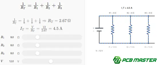
When two or more resistors are connected between the same pair of circuit nodes, they are resistors in parallel .
Unlike a series connection, where the same current flows through every resistor, a parallel network has:
- The same voltage across each resistor
- Different branch currents depending on resistance
- A total current equal to the sum of all branch currents
- An equivalent resistance lower than the smallest resistor
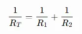
For a simple two-resistor network:
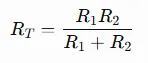
Therefore:
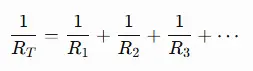
For three or more resistors:
This relationship is one of the fundamental rules used in circuit analysis and PCB design.
How Do Resistors in Parallel Work?
Consider two resistors, R₁ = 100 Ω and R₂ = 200 Ω , connected in parallel to a 10 V supply.
Because both resistors are connected to the same two nodes, each resistor receives 10 V .
Using Ohm's law :
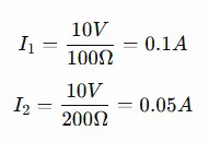
The total current is:
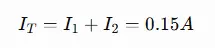
The equivalent resistance is therefore:
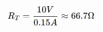
The result demonstrates an important characteristic:
Adding a resistor in parallel decreases the total resistance and increases the total current drawn from the source at a fixed voltage.
The lower-value resistor carries more current because current divides inversely according to resistance.
Resistors in Parallel vs. Resistors in Series
Parallel and series resistor networks behave differently and serve different circuit-design purposes.
| Parameter | Resistors in Parallel | Resistors in Series |
|---|---|---|
| Voltage | Same across each resistor | Divided between resistors |
| Current | Divided between branches | Same through all resistors |
| Equivalent resistance | Lower than the smallest resistor | Sum of all resistors |
| Adding another resistor | Decreases total resistance | Increases total resistance |
| Current path | Multiple paths | Single path |
| Typical applications | Current sharing, loading, redundancy, resistance adjustment | Voltage division, current limiting, timing networks |
The distinction is particularly important when designing a PCB because the physical connection determines the electrical behavior.
How to Calculate Equivalent Resistance of Parallel Resistors
Two Resistors in Parallel
For two resistors, the product-over-sum formula is usually the fastest method:
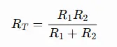
For example, if:
- R₁ = 100 Ω
- R₂ = 100 Ω
Then:
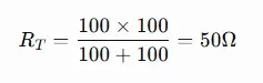
Two equal resistors in parallel always produce an equivalent resistance equal to half the value of either resistor .
Multiple Resistors in Parallel
For three or more resistors, use the reciprocal relationship:
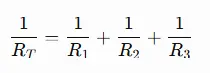
For example:
- R₁ = 100 Ω
- R₂ = 200 Ω
- R₃ = 300 Ω
Then:
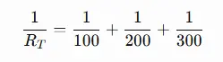
The equivalent resistance will be lower than 100 Ω , which is the smallest resistor in the network.
Equal Resistors in Parallel
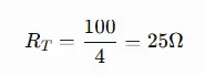
If all resistors have the same resistance value, calculation becomes simpler:
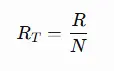
where:
- R = resistance of each resistor
- N = number of identical resistors
For four 100 Ω resistors:
This configuration is commonly useful when designers need a resistance value or power rating that is difficult to obtain from a single standard resistor.
Why Is the Equivalent Resistance Lower in Parallel?
The easiest way to understand this is through current flow .
A single resistor provides one path for current. Adding another resistor in parallel creates an additional path between the same two nodes.
At a fixed voltage:
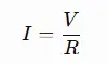
Each branch contributes additional current. Since the source current is the sum of the branch currents, the overall current increases.
Because equivalent resistance is:
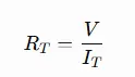
a higher total current at the same voltage means a lower equivalent resistance.
This is analogous to adding additional lanes to a road: the available path for traffic increases, reducing the overall resistance to flow.
Current Distribution in Parallel Resistors
Current does not necessarily divide equally between parallel resistors.
For two parallel resistors:
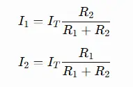
The resistor with the lower resistance carries more current .
For example, if 10 Ω and 100 Ω resistors are connected in parallel, the 10 Ω resistor carries approximately ten times the current of the 100 Ω resistor under the same voltage.
This matters when selecting resistor packages and power ratings.
A designer should not assume that the total power is distributed equally among the components unless the resistance values are equal.
Power Dissipation in Parallel Resistors
Power is another important consideration.
For an individual resistor:
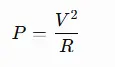
Because every parallel resistor has the same voltage, the resistor with the lower resistance dissipates more power .
For example, with 10 V applied:
- 100 Ω resistor: P=1W
- 200 Ω resistor: P=0.5W
Therefore, the 100 Ω resistor requires greater power-handling capability.
Why Power Rating Matters in PCB Design
A resistor may have the correct resistance value but still fail if its power rating is insufficient.
Common considerations include:
- Continuous operating power
- Ambient temperature
- PCB copper area
- Component package size
- Thermal dissipation
- Temperature rise
- Pulse or transient conditions
- Derating requirements
For high-power applications, designers may use multiple resistors in parallel to distribute heat and electrical stress.
Why Use Resistors in Parallel?
Parallel resistor networks are not simply a mathematical technique. They have several practical applications in electronic design.
1. Achieving a Non-Standard Resistance Value
Designers sometimes need a resistance value that is not readily available as a standard component.
Combining standard resistor values in parallel can produce a required effective resistance.
For example, two resistors can be selected to approximate a target resistance while maintaining practical component availability.
2. Increasing Power Handling
Multiple resistors can share power dissipation.
Suppose two identical resistors are connected in parallel. If current is reasonably balanced between them, each resistor can dissipate part of the total power.
This can be useful when:
- A single resistor's power rating is insufficient
- A higher-power package is unavailable
- Thermal distribution is important
- Component sourcing needs greater flexibility
However, resistor tolerance and temperature coefficient should be considered because unequal resistance values result in unequal current sharing.
3. Current Sharing
Parallel resistors can be used to establish controlled current paths.
This approach appears in various circuits involving:
- Power electronics
- Load networks
- Current sensing
- Termination
- Bias networks
- Protection circuits
4. Fine-Tuning Circuit Resistance
A primary resistor can be combined with another resistor to adjust the effective resistance without changing the main component.
This can be useful during circuit optimization or when accommodating standard resistor values.
Common Mistakes When Using Parallel Resistors
Mistake 1: Adding Resistance Values Directly
A frequent error is calculating:
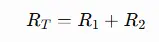
This formula applies to series resistors , not parallel resistors.
For parallel resistors, the reciprocal formula must be used.
Mistake 2: Assuming Current Is the Same
Current is the same in a series network, but not in a parallel network.
In parallel:
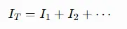
Each branch current depends on its resistance.
Mistake 3: Assuming Power Is Shared Equally
Power sharing is only equal when the relevant resistors have equal electrical conditions.
Different resistance values result in different current and power levels.
Mistake 4: Ignoring PCB Layout
Two resistors may be mathematically parallel in the schematic but behave differently in practice if the PCB introduces significant parasitic resistance, inductance, or thermal imbalance.
For ordinary low-frequency resistor networks, these effects may be negligible. For precision, high-current, or high-speed designs, however, PCB layout becomes much more important.
PCB Layout Considerations for Parallel Resistors
When parallel resistors are implemented on a PCB, the schematic is only part of the design.
Keep Current Paths Balanced
If two resistors are intended to share current, the PCB traces should provide reasonably symmetrical paths.
An unbalanced layout can introduce different trace resistance between branches, causing one resistor to carry more current than intended.
Consider Thermal Coupling
Parallel resistors that dissipate significant power generate heat.
Their placement should account for:
- Copper area
- Thermal vias where applicable
- Nearby heat-sensitive components
- Airflow
- Component spacing
- Local temperature rise
Select Appropriate Resistor Packages
Larger packages generally provide greater power-handling capability, although actual performance depends on the resistor technology and manufacturer specifications.
For high-power applications, using several appropriately rated resistors may provide better thermal distribution than relying on one component.
Account for Tolerance
Suppose two nominally identical resistors are specified at 100 Ω but have different tolerances.
Their actual resistance values may differ, meaning their currents will not divide perfectly equally.
For precision or current-sharing applications, consider:
- Resistance tolerance
- Temperature coefficient
- Long-term stability
- Resistor technology
- Operating temperature
Parallel Resistors in Real PCB Applications
Parallel resistor networks can appear across many PCB applications.
| Application | Why Parallel Resistors May Be Used |
|---|---|
| Power electronics | Power distribution and load management |
| Current sensing | Resistance and power optimization |
| Signal termination | Achieving specific effective impedance |
| LED circuits | Current limiting or load configuration |
| Industrial control | Bias and conditioning networks |
| Automotive electronics | Robust resistance and power handling |
| Communication electronics | Termination and circuit matching |
| General PCB design | Obtaining non-standard resistance values |
The appropriate implementation depends on voltage, current, frequency, tolerance, thermal conditions, and reliability requirements.
Resistors in Parallel: Practical Design Example
Consider a PCB power circuit requiring an effective resistance of approximately 50 Ω.
Instead of using a single 50 Ω resistor, a designer could use:
- Two 100 Ω resistors in parallel
The resulting equivalent resistance is:
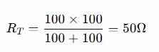
If the total power requirement is 2 W and the two resistors are identical and properly thermally coupled, the nominal power distribution can be approximately:
- R₁: 1 W
- R₂: 1 W
This can provide a practical way to distribute heat across two components.
However, the design should still verify the resistor manufacturer's power derating specifications and the actual PCB thermal environment rather than relying solely on theoretical equal sharing.
Parallel Resistors vs. a Single Resistor
| Design Factor | Parallel Resistors | Single Resistor |
|---|---|---|
| Resistance flexibility | High | Depends on available values |
| Power distribution | Can be distributed | Concentrated |
| PCB area | Usually higher | Usually lower |
| Component count | Higher | Lower |
| Thermal distribution | Potentially better | More concentrated |
| Current sharing | Requires consideration | Not applicable |
| BOM complexity | Higher | Lower |
| Sourcing flexibility | Can be advantageous | Depends on required value/rating |
The best solution is therefore not always the one with the lowest component count.
For production PCB design, engineers should evaluate electrical performance, thermal behavior, component availability, assembly cost, and long-term reliability together .
How Parallel Resistor Networks Affect PCB Manufacturing
A resistor network that appears simple electrically can still affect PCB manufacturability.
Component selection and placement influence:
- SMT component density
- Pad geometry
- Assembly yield
- AOI inspection
- Thermal performance
- Rework accessibility
- BOM cost
- PCB routing
For example, replacing one high-power resistor with several smaller resistors may improve thermal distribution but increase placement density and assembly operations.
This is why resistor selection should be evaluated together with the overall PCB and PCBA manufacturing process rather than treated as an isolated schematic decision.
PCBMASTER's Approach to PCB and PCBA Manufacturing
For designs incorporating parallel resistor networks, PCBMASTER provides PCB, PCBA, and SMT manufacturing support from prototype development through production.
Its engineering service includes free engineering document checking , allowing potential manufacturability, performance, and cost issues to be identified before production. This can be particularly useful when a resistor network involves tight component spacing, specific thermal requirements, or complex PCB routing.
PCBMASTER operates its own 80,000 m² factory and supports conventional and advanced PCB technologies, including HDI , FPC , rigid-flex , high-frequency PCB , and metal-core PCB manufacturing. Its quality systems include ISO 9001, IATF 16949, UL, and RoHS certifications .
For projects requiring parallel resistor networks in demanding applications, manufacturing considerations should be incorporated during the engineering review rather than after the PCB layout is finalized.
How to Choose the Right Parallel Resistor Configuration
Before implementing parallel resistors, engineers should evaluate the following:
Electrical Requirements
Determine:
- Required equivalent resistance
- Operating voltage
- Total current
- Branch current
- Total power
- Individual resistor power
Component Requirements
Check:
- Resistance value
- Resistance tolerance
- Power rating
- Temperature coefficient
- Package size
- Voltage rating
- Availability
- Lifecycle status
PCB Requirements
Evaluate:
- Available board area
- Trace width
- Copper thickness
- Thermal management
- SMT placement
- Inspection accessibility
- Assembly requirements
Reliability Requirements
For demanding applications, consider:
- Temperature cycling
- Continuous thermal loading
- Electrical overstress
- Component aging
- Tolerance drift
- Manufacturing variation
A theoretically correct resistor calculation is only the starting point. A production-ready design must also remain stable under its real operating conditions.
Frequently Asked Questions About Resistors in Parallel
What happens when resistors are connected in parallel?
Each resistor has the same voltage across it, while the total current divides among the individual branches. The equivalent resistance becomes lower than the smallest resistor.
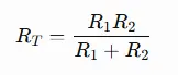
What is the formula for two resistors in parallel?
The standard formula is:
Is resistance lower in parallel?
Yes. The equivalent resistance of multiple positive-valued resistors in parallel is always lower than the smallest individual resistance.
Do parallel resistors have the same current?
No. They have the same voltage, but branch current depends on resistance. A lower resistance normally carries more current.
Can resistors in parallel increase power rating?
Yes, using multiple appropriately selected resistors can distribute power dissipation. However, actual power sharing depends on resistance tolerance, temperature, layout, and operating conditions.
Why would you use two resistors in parallel instead of one?
Common reasons include achieving a specific resistance, distributing power, improving thermal management, using readily available component values, or meeting particular design constraints.
Final Takeaway
Resistors in parallel provide multiple current paths between the same two nodes, resulting in the same voltage across each resistor and a lower equivalent resistance. The basic calculation is straightforward, but practical circuit design requires more than applying the parallel-resistance formula.
Engineers should also consider current distribution, power dissipation, resistor tolerance, temperature coefficient, PCB layout, thermal management, component availability, and manufacturing requirements .
For PCB and PCBA projects, these factors become especially important when resistor networks operate at high current, dissipate significant power, or are used in precision and automotive applications. A proper design-for-manufacturing review can identify potential issues before they become production problems.
Tags: #ResistorsInParallel #ParallelResistor #Resistor #PCBDesign #PCBA #SMT #CircuitDesign #Electronics #PCBManufacturing #PCBMASTER #ElectronicsEngineering
About the Author

Carol Luo
PCB Design EngineerI'm Carol, a PCB Engineer at PCBMASTER with experience in PCB design and manufacturing engineering since 2018. I focus on translating engineering requirements into reliable PCB solutions, with expertise in stack-up design, material selection, and design-for-manufacturing (DFM). I share practical engineering insights from real-world PCB design and production experience.
Visit Carol Luo's Profile

