








Surface Mount Capacitor: Types, Specifications, Applications, and PCB Assembly Considerations
Surface mount capacitors, commonly called SMD capacitors, are compact passive components widely used for decoupling, filtering, energy storage, timing, and signal conditioning in modern electronic assemblies. Selecting the right surface mount capacitor requires more than matching capacitance and voltage. Package size, dielectric type, tolerance, temperature characteristics, ESR, ripple current, DC bias behavior, polarity, PCB layout, and reflow conditions can all affect circuit reliability. This guide explains the major surface mount capacitor types, key specifications, selection criteria, and PCB assembly considerations from a practical manufacturing perspective.
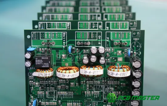
What Is a Surface Mount Capacitor?
A surface mount capacitor is a capacitor designed to be mounted directly onto the surface of a printed circuit board (PCB) rather than inserted through drilled holes.
Unlike traditional through-hole capacitors, SMD capacitors have terminals or electrodes positioned for automated surface mount assembly. Their compact dimensions make them particularly suitable for high-density electronic products where PCB space is limited.
Surface mount capacitors are commonly used for:
- Power supply decoupling
- Voltage stabilization
- Noise suppression
- Signal filtering
- AC coupling
- Energy storage
- Timing and frequency circuits
- EMI and RF filtering
A typical SMD capacitor may look simple, but its electrical behavior depends heavily on its dielectric material, construction, package, operating conditions, and PCB assembly process.
For engineers selecting components for a new PCB design, the important question is therefore not simply “What capacitor value do I need?” but rather “Which capacitor technology provides the required electrical and mechanical performance under my actual operating conditions?”
What Are the Main Types of Surface Mount Capacitors?
Several capacitor technologies are available in surface mount packages. The most common choice for general-purpose PCB designs is the multilayer ceramic capacitor (MLCC) , but other technologies can be important for specific applications.
| Surface Mount Capacitor Type | Typical Characteristics | Common Applications | Key Considerations |
|---|---|---|---|
| MLCC | Small, low ESR, high-frequency performance | Decoupling, filtering, RF, digital circuits | DC bias, cracking, capacitance derating |
| Tantalum | Stable capacitance and relatively high volumetric efficiency | Power supply filtering, industrial electronics | Polarity, surge current, voltage derating |
| Aluminum Polymer | Low ESR and good ripple-current capability | Power conversion, DC/DC circuits | Temperature and voltage ratings |
| Aluminum Electrolytic SMD | Higher capacitance in compact packages | Bulk filtering, power supplies | Polarity, ESR, lifetime |
| Film SMD Capacitor | Good stability and electrical characteristics | Filtering, precision and specialized circuits | Larger physical size |
| Silicon Capacitor | Very small and specialized | RF, high-density applications | Application-specific characteristics |
MLCC: The Most Common Surface Mount Capacitor
Multilayer ceramic capacitors (MLCCs) are extensively used in modern PCB designs because they offer a combination of small size, low parasitic inductance, low ESR, and strong high-frequency performance.
They are frequently placed close to:
- IC power pins
- Microcontrollers
- Processors
- DC/DC converters
- RF circuits
- High-speed digital devices
However, an MLCC's nominal capacitance does not always represent its effective capacitance under operating conditions.
For example, some ceramic dielectric classes exhibit significant capacitance reduction when DC voltage is applied. Therefore, designers should evaluate effective capacitance under the actual DC bias , rather than relying exclusively on the nominal value printed in a component database.
Which Surface Mount Capacitor Specifications Matter?
Choosing an SMD capacitor involves evaluating several specifications together.
1. Capacitance
Capacitance determines how much electrical charge a capacitor can store for a given voltage.
Common capacitance values span a very broad range, from extremely small values used in RF circuits to much larger values used for power filtering.
However, the nominal capacitance alone is not enough.
A capacitor specified as a particular capacitance may exhibit different effective values depending on:
- Applied DC voltage
- Temperature
- Frequency
- Aging
- Dielectric material
- Manufacturing tolerance
For power decoupling, engineers should therefore consider the capacitance that remains available under actual operating conditions .
2. Rated Voltage
The rated voltage indicates the maximum operating voltage under specified conditions.
A practical design should provide an appropriate voltage margin rather than operating a capacitor continuously at its absolute rated limit.
The required margin depends on:
- Nominal circuit voltage
- Voltage transients
- Ripple
- Temperature
- Capacitor technology
- Reliability requirements
For demanding applications, voltage derating can be particularly important.
3. Tolerance
Capacitance tolerance indicates how much the actual capacitance can differ from its nominal value.
A tight tolerance may be important in:
- Timing circuits
- Filters
- Resonant circuits
- Precision analog designs
- RF applications
For many general-purpose decoupling applications, however, extreme capacitance precision may be less important than package size, voltage rating, effective capacitance, and frequency behavior.
4. Dielectric
For ceramic capacitors, dielectric selection strongly influences performance.
Different dielectric classes provide different combinations of:
- Capacitance stability
- Temperature characteristics
- Voltage sensitivity
- Aging behavior
- Size efficiency
This is why simply specifying “ceramic capacitor” is not sufficient for many engineering applications.
5. ESR and ESL
Equivalent Series Resistance (ESR) and Equivalent Series Inductance (ESL) influence how effectively a capacitor responds to changing currents.
Low ESR can be valuable in power supply applications, while low ESL is particularly useful when dealing with high-frequency transients.
The physical connection between the capacitor and the PCB also matters. Even a capacitor with favorable intrinsic electrical characteristics can perform differently when PCB trace length, via structure, pad geometry, and placement introduce additional parasitics.
6. Temperature Characteristics
A surface mount capacitor must operate within the temperature range expected by the final product.
Temperature can affect:
- Capacitance
- ESR
- Leakage current
- Reliability
- Lifetime
For automotive, industrial, power electronics, and other demanding applications, engineers should evaluate the component across the complete expected operating temperature range rather than relying only on room-temperature specifications.
Surface Mount Capacitor Package Size Matters
SMD capacitors are available in numerous package sizes. Smaller packages help reduce PCB area, while larger packages can provide advantages in voltage rating, capacitance, mechanical robustness, or thermal behavior depending on the capacitor technology.
Common ceramic capacitor package designations include:
- 0201
- 0402
- 0603
- 0805
- 1206
- 1210
The actual dimensions represented by these designations depend on the applicable package standard and manufacturer.
Small Package vs. Large Package
| Design Consideration | Smaller Package | Larger Package |
|---|---|---|
| PCB Area | Lower | Higher |
| Component Density | Higher | Lower |
| Automated Placement | Suitable with appropriate equipment | Generally straightforward |
| Mechanical Stress Sensitivity | Can require careful handling | Package-dependent |
| Available Capacitance/Voltage Options | Application-dependent | Often broader for some technologies |
| Layout Flexibility | High-density designs | More board space required |
The smallest available component is not automatically the correct component.
A good design balances electrical requirements, assembly capability, mechanical reliability, PCB space, and component availability .
How Are Surface Mount Capacitors Used on a PCB?
Surface mount capacitors perform different functions depending on where they are placed within the circuit.
Decoupling and Bypass
One of the most common uses is placing a capacitor near an IC power pin.
The capacitor provides a local charge reservoir and helps reduce high-frequency voltage fluctuations associated with rapidly changing current demand.
For effective decoupling, placement is critical.
The capacitor should generally be positioned close to the relevant power and ground connections, with a low-inductance current path.
Power Supply Filtering
Surface mount capacitors are also used around:
- Voltage regulators
- DC/DC converters
- LDOs
- Power-management ICs
- Battery-management circuits
Here, capacitor selection should consider the regulator's stability requirements, ripple current, ESR, capacitance range, and transient behavior.
Signal Filtering
Capacitors can work with resistors and inductors to create filtering networks.
Depending on the circuit configuration, they can contribute to:
- Low-pass filters
- High-pass filters
- Band-pass networks
- EMI suppression
- RF filtering
AC Coupling
A capacitor can block a DC component while allowing an AC signal to pass.
This makes surface mount capacitors useful in communication, audio, RF, and other signal-conditioning circuits.
Surface Mount Capacitor Selection: A Practical Engineering Process
A systematic selection process can reduce redesigns and manufacturing problems.
Step 1: Define the Electrical Requirement
Start with:
- Required capacitance
- Operating voltage
- Tolerance
- Frequency range
- Ripple current
- Temperature range
Do not select the package before understanding these requirements.
Step 2: Determine the Capacitor Technology
Choose among ceramic, tantalum, polymer, electrolytic, film, or other technologies according to the circuit's electrical and reliability requirements.
For high-frequency decoupling, an MLCC may be appropriate. For bulk energy storage, a different capacitor technology may be more suitable.
Step 3: Check Derating
Evaluate how capacitance and other electrical characteristics change under actual operating voltage and temperature.
This is especially important for ceramic capacitors because the effective capacitance can differ substantially from the nominal value under DC bias.
Step 4: Select the Package
Choose a package compatible with:
- PCB space
- Required capacitance
- Rated voltage
- Assembly process
- Mechanical environment
- Reliability requirements
Step 5: Verify Availability
Component availability should be considered before finalizing the BOM.
A technically suitable capacitor can still become a production problem if its supply is unstable or if the approved component has limited sourcing options.
Step 6: Verify PCB Assembly Compatibility
The selected capacitor must be compatible with the PCB's SMT assembly process, including:
- Solder paste deposition
- Pad geometry
- Pick-and-place
- Reflow profile
- Component orientation
- Inspection
- Handling
This is where component selection and PCB manufacturing engineering need to work together.
Common Surface Mount Capacitor Design and Assembly Mistakes
Mistake 1: Selecting Only by Capacitance
A capacitor with the correct nominal capacitance may still be unsuitable because of voltage, temperature, ESR, DC bias, or package limitations.
Better approach: Evaluate the complete electrical specification.
Mistake 2: Ignoring DC Bias
This is particularly important for MLCCs.
The effective capacitance under operating voltage can be lower than the nominal specification.
Better approach: Review the manufacturer's DC-bias characteristics and design using the expected effective capacitance.
Mistake 3: Using the Smallest Package Automatically
Miniaturization is valuable, but smaller components can impose tighter requirements on PCB design, placement, inspection, and mechanical handling.
Better approach: Select the smallest package that satisfies both engineering and manufacturing requirements.
Mistake 4: Poor Decoupling Placement
A theoretically correct capacitor can provide limited benefit if it is connected through unnecessarily long or inductive PCB paths.
Better approach: Keep high-frequency decoupling paths short and low impedance.
Mistake 5: Ignoring Reflow Conditions
Surface mount capacitors are exposed to thermal stress during soldering.
Improper reflow conditions can contribute to soldering defects or component reliability problems.
Better approach: Follow the component manufacturer's assembly recommendations and validate the complete SMT process.
Mistake 6: Treating All Capacitors as Interchangeable
Two capacitors with the same capacitance, voltage rating, and package can still have different electrical and reliability characteristics.
Better approach: Compare the complete datasheets and approved component specifications.
Surface Mount Capacitors and SMT Assembly
Because SMD capacitors are designed for surface mounting, their performance is closely connected to the SMT manufacturing process.
A typical assembly flow includes:
PCB Preparation → Solder Paste Printing → Solder Paste Inspection → Component Placement → Reflow Soldering → AOI → Electrical/Functional Testing → Final Inspection
Solder Paste Printing
Incorrect solder paste volume or stencil design can contribute to soldering defects.
For small passive components, consistent paste deposition is particularly important because the component dimensions and pad spacing can be very small.
Pick-and-Place
Automated placement equipment must accurately position the capacitor on the PCB pads.
Placement accuracy, component feeding, and machine setup all contribute to assembly consistency.
Reflow Soldering
The PCB passes through a controlled thermal profile to melt the solder paste and form solder joints.
The reflow profile must be compatible with the solder materials and components being assembled.
AOI Inspection
Automated Optical Inspection can help identify visible assembly defects such as:
- Component displacement
- Missing components
- Soldering abnormalities
- Polarity-related placement issues where visually detectable
- Other assembly defects
For high-reliability PCB assemblies, AOI is one part of a broader quality-control process rather than a replacement for all other forms of inspection and testing.
Surface Mount Capacitor Selection by Application
Different applications place different demands on capacitors.
| Application | Typical Capacitor Role | Important Selection Factors |
|---|---|---|
| Consumer Electronics | Decoupling, filtering | Size, cost, capacitance, availability |
| Industrial Control | Filtering, decoupling, power conditioning | Temperature, reliability, voltage margin |
| Automotive Electronics | Power filtering, signal conditioning | Temperature, reliability, qualification requirements |
| Communications | RF filtering, decoupling | Frequency behavior, parasitics, stability |
| Power Electronics | Bulk filtering, ripple suppression | Ripple current, ESR, voltage, temperature |
| Battery Systems | Filtering and power management | Voltage, temperature, reliability |
| High-Speed Digital | Power integrity and decoupling | ESL, placement, effective capacitance |
| Medical Electronics | Filtering, signal conditioning, power stability | Reliability, qualification, application requirements |
The correct component depends on the actual circuit and operating environment. There is no single surface mount capacitor specification that is optimal for every PCB application.
How PCB Design Affects Surface Mount Capacitor Performance
Component selection is only one part of the engineering equation.
The PCB itself influences capacitor performance through:
- Pad geometry
- Trace length
- Ground-plane structure
- Via placement
- Current-loop area
- Component spacing
- Thermal design
- Stack-up
For high-speed and high-frequency circuits, these factors become increasingly important because parasitic inductance and impedance can influence the effectiveness of the capacitor at higher frequencies.
Therefore, component selection, schematic design, PCB layout, stack-up design, and manufacturing engineering should be considered together .
Surface Mount Capacitor: What Should Engineers Verify Before Production?
Before releasing a PCB design for production, engineers and procurement teams should verify several areas.
Electrical Verification
Check:
- Capacitance
- Rated voltage
- Tolerance
- Dielectric
- Temperature range
- ESR/ESL where relevant
- Ripple-current capability where relevant
- DC-bias behavior where relevant
Mechanical Verification
Check:
- Package dimensions
- PCB footprint
- Component height
- Pad design
- Clearance
- Mechanical stress considerations
Manufacturing Verification
Check:
- SMT placement capability
- Stencil design
- Solder paste requirements
- Reflow compatibility
- AOI inspection
- Component sourcing
- Alternative components
Supply Chain Verification
A component should not be selected purely from an electrical perspective. For production projects, stable material availability can directly affect manufacturing continuity.
A PCB manufacturer with established material sourcing and engineering support can identify potential component or fabrication issues before they become production problems.
How PCBMASTER Supports Surface Mount Capacitor PCB Projects
As a PCB and PCBA manufacturer serving industries that use PCB, PCBA, and SMT technologies, PCBMASTER combines PCB fabrication, SMT assembly, PCBA production, component sourcing, and engineering support within one manufacturing system .
PCBMASTER operates an 80,000㎡ factory and provides PCB and PCBA services covering prototypes through larger-scale production. Its manufacturing capabilities include standard and advanced PCB technologies such as HDI , high-frequency PCB , FPC , rigid-flex PCB , and metal-core PCB .
For projects using surface mount capacitors, the manufacturing process is not limited to placing components on a board. Engineering review can also evaluate the supplied manufacturing files before production.
Free Engineering File Checking
PCBMASTER provides free engineering file review in which professional technicians check supplied files for manufacturability, PCB performance considerations, and cost-effectiveness.
Potential issues can be identified before fabrication and assembly, helping reduce avoidable production problems.
SMT and PCBA Manufacturing
Surface mount capacitors are part of the broader SMT assembly process. PCBMASTER provides PCB and PCBA manufacturing with quality-control processes that include AOI inspection and multiple quality inspections , while all boards undergo testing before shipment according to the company's stated quality process.
For projects that move from prototype to production, keeping PCB fabrication and SMT assembly under one manufacturing workflow can also simplify engineering communication and production coordination.
Quality and Compliance
PCBMASTER's stated quality credentials include ISO 9001, IATF 16949, UL Certification, and RoHS certification . IATF 16949 is particularly relevant when PCB and PCBA projects involve automotive electronics and automotive supply-chain requirements.
PCBMASTER also states that it maintains a 99.5% product yield rate and a 99.59% on-time delivery rate , while offering 24-hour online service and engineering support.
These figures are company-provided operational claims and should be evaluated against the requirements and verification procedures of a specific project.
A Practical Surface Mount Capacitor Checklist
Before approving an SMD capacitor for production, use this checklist:
Electrical
- Required capacitance confirmed
- Rated voltage confirmed
- Appropriate voltage margin established
- Tolerance verified
- Dielectric verified
- Effective capacitance under DC bias checked
- Temperature characteristics checked
- ESR/ESL evaluated where relevant
- Ripple-current capability evaluated where relevant
PCB Design
- Correct footprint used
- Pad geometry verified
- Decoupling components positioned appropriately
- Ground/current paths reviewed
- Clearance verified
- Component height checked
SMT Manufacturing
- Component package compatible with assembly
- Stencil design reviewed
- Pick-and-place compatibility confirmed
- Reflow profile verified
- AOI inspection capability confirmed
- Testing requirements defined
Production
- BOM manufacturer part number verified
- Component availability checked
- Approved alternatives identified where necessary
- Engineering files reviewed
- Quality requirements documented
Summary
A surface mount capacitor is a small component with a potentially significant influence on PCB electrical performance and assembly reliability. The right selection requires consideration of capacitance, voltage, tolerance, dielectric, temperature characteristics, DC-bias behavior, ESR, ESL, package size, and application requirements.
For PCB designers, the selection process should extend beyond the component datasheet. Footprint design, capacitor placement, PCB stack-up, power distribution, SMT assembly, reflow, inspection, testing, and component supply should all be considered as part of the same manufacturing process.
For complex PCB projects, early engineering review can help identify problems before they reach production. PCBMASTER's combination of PCB manufacturing, PCBA assembly, SMT capabilities, engineering file checking, component sourcing, and prototype-to-production support provides one manufacturing route for projects using surface mount capacitors across different electronic applications.
FAQs About Surface Mount Capacitors
What is a surface mount capacitor?
A surface mount capacitor is a capacitor designed to be soldered directly onto the surface of a PCB. It is commonly used for decoupling, filtering, power conditioning, signal coupling, and energy storage.
What is the most common type of SMD capacitor?
MLCCs are among the most widely used surface mount capacitors, particularly in compact digital, power, communication, and consumer-electronics PCB designs.
Are surface mount capacitors polarized?
It depends on the capacitor technology. Many ceramic capacitors are non-polarized, while tantalum and many electrolytic capacitors are polarized. The component datasheet should always be checked before PCB assembly.
How do I choose a surface mount capacitor?
Start with the required capacitance and voltage, then evaluate dielectric, tolerance, temperature characteristics, DC-bias behavior, ESR/ESL, package size, application frequency, reliability requirements, and component availability.
Why does capacitor placement matter on a PCB?
Placement affects the electrical path between the capacitor and the circuit. For high-frequency decoupling, shorter and lower-inductance connections can improve the capacitor's effectiveness.
Can surface mount capacitors be used in automotive PCBs?
Yes. Surface mount capacitors are widely used in automotive electronics, but the component and PCB/PCBA manufacturing process must satisfy the specific electrical, environmental, reliability, and qualification requirements of the application.
What should I check before assembling SMD capacitors?
Check the BOM, capacitor specifications, PCB footprint, polarity where applicable, stencil and pad design, component placement, reflow profile, inspection requirements, and component sourcing.
Why is DC bias important for MLCCs?
Some ceramic capacitors can experience a reduction in effective capacitance when DC voltage is applied. Therefore, the effective capacitance at the actual operating voltage should be considered rather than relying only on the nominal capacitance.
Can a PCB manufacturer help review surface mount capacitor designs?
Yes. An experienced PCB/PCBA manufacturer can review manufacturing files, footprints, assembly requirements, and other production-related considerations before fabrication and assembly. PCBMASTER provides free engineering file checking as part of its stated engineering support.
Tags
#SurfaceMountCapacitor #SMDCapacitor #SMD #MLCC #PCB #PCBA #SMT #PCBAssembly #PCBDesign #Electronics #Capacitor #PCBManufacturing #ElectronicsManufacturing#PCBMASTER
About the Author

Carol Luo
PCB Design EngineerI'm Carol, a PCB Engineer at PCBMASTER with experience in PCB design and manufacturing engineering since 2018. I focus on translating engineering requirements into reliable PCB solutions, with expertise in stack-up design, material selection, and design-for-manufacturing (DFM). I share practical engineering insights from real-world PCB design and production experience.
Visit Carol Luo's Profile

