








Resistor Fix: Common Problems, Troubleshooting Methods, and PCB Repair Solutions
Resistors can fail in ways that compromise circuit stability, signal integrity, power distribution and the overall reliability of electronic systems. PCB engineers, electronics manufacturers and repair technicians need to know how to diagnose problems on resistors, how to diagnose the causes of failure and how to implement effective fixes on resistors. This guide covers common resistor faults, how to test for them, where to find replacements and how professional PCB manufacturing practices can help you avoid resistor-related issues in your electronic products.
What Is a Resistor and Why Does It Need Fixing?
One of the most basic electronic components used in PCB and PCBA design is resistor. It is used for current limiting, voltage division, biasing and protecting sensitive components from excessive electrical stress .
In real electronic applications resistors can fail due to:
- Excessive current overload
- High operating temperature
- Incorrect component selection
- Poor soldering quality
- Mechanical damage
- Moisture or environmental stress
- PCB design issues
In a circuit , a failing resistor might exhibit symptoms such as unstable voltage , abnormal current flow , overheating , signal distortion , or even complete system failure .
The proper way to repair a resistor is to find out what made it blow in the first place. So simply replacing the blown resistor is not a fix .
Common Resistor Problems and How to Fix Them
1. Burned or Overheated Resistor
One of the most common resistor failures is visible burning or discoloration.
Possible Causes:
- The resistor power rating is too low
- Excessive current passes through the component
- Heat dissipation is insufficient
- A downstream component has a short circuit
A resistor converts electrical energy into heat. If the heat generated is more than the power rating of the resistor, the component may heat and eventually fail.
Resistor Fix:
Step 1: Check the resistor value
Measure resistance with a multimeter and compare to the circuit specification.
Step 2: Identify the overload source
Check nearby parts especially:
- ICs
- Capacitors
- Transistors
- Power supply circuits
Step 3: Replace with a suitable resistor
The replacement needs to consist of:
| Parameter | Incorrect Selection | Recommended Practice |
|---|---|---|
| Resistance value | Wrong resistance causes circuit malfunction | Match the original design value |
| Power rating | Low wattage causes overheating | Select adequate power margin |
| Package size | Small package limits heat dissipation | Choose suitable PCB footprint |
2. Incorrect Resistance Value
Sometimes a resistor looks good but the value of the resistance has drifted.
Common Reasons:
- Long-term thermal stress
- Aging
- Excessive voltage exposure
- Manufacturing defects
In precision circuits small resistance deviations can affect:
- Voltage reference circuits
- Sensor measurements
- Communication interfaces
- Analog signal processing
How to Fix:
Use a digital multimeter to measure resistance.
In general you want to measure the resistor with the power off and isolated from the circuit so you don't get any interference from parallel paths.
If the measured value is out of tolerance, the part needs to be replaced.
3. Broken or Poor Solder Connection
PCB assembly resistor failures are not always the component’s fault. Solder joints are a problem.
Typical Solder Issues:
- Cold solder joints
- Insufficient solder volume
- Solder cracks
- Component lifting
- Poor SMT placement accuracy
These problems can cause intermittent failure that is difficult to trace.
Resistor Fix:
For SMT resistor repair:
- Remove the damaged resistor using proper rework equipment.
- Clean PCB pads.
- Apply solder paste or solder.
- Place the replacement component.
- Perform solder inspection.
AOI (Automated Optical Inspection) and X-ray inspection are able to find hidden solder defects for high-density PCB assemblies.
4. Wrong Resistor Placement During PCB Assembly
Today's PCB assembly will often have hundreds or thousands of resistors. Reasons for incorrect placement are:
- Incorrect BOM files
- Wrong component package
- Pick-and-place programming errors
- Human assembly mistakes
A misplaced resistor may cause:
- Short circuits
- Incorrect signal levels
- Functional failure
Prevention Methods:
| Quality Control Stage | Purpose |
|---|---|
| Engineering review | Verify BOM and PCB files |
| SMT programming | Ensure accurate component placement |
| AOI inspection | Detect placement and solder defects |
| Functional testing | Confirm electrical performance |
How to Diagnose a Failed Resistor on a PCB
Troubleshooting using a systematic approach will help increase repair efficiency.
Step 1: Visual Inspection
Check for:
- Burn marks
- Cracks
- Missing components
- Poor solder joints
Step 2: Resistance Measurement
Switch your multimeter to resistance mode.
Important:
- Disconnect power before measurement
- Compare with schematic values
- Consider parallel circuits
Step 3: Voltage Testing
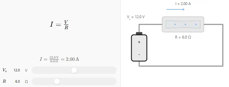
Measure the voltage across the resistor when it is operating.
Unexpected voltage drops may indicate:
- Excessive current
- Incorrect circuit operation
- Component failure
Step 4: Replace and Verify
After replacing the resistor:
- Test circuit functionality
- Check operating temperature
- Confirm stable performance
Resistor Selection Considerations for PCB Design
You can avoid resistor failures before you design the PCB.
1. Select the Correct Power Rating
Engineers should estimate the expected power consumption and stay away from operating the resistors near their maximum rating.
Common resistor power ratings include:
| Resistor Type | Typical Application |
|---|---|
| 0.125W | Low-power signal circuits |
| 0.25W | General electronic circuits |
| 0.5W-1W | Higher power applications |
| High-power resistors | Industrial and power electronics |
2. Consider Thermal Management
For high-power applications, PCB designers should consider:
- Copper area
- Thermal vias
- Component spacing
- Heat dissipation paths
Resistors are less reliable and have a shorter life if the thermal design is not good.
3. Verify PCB Manufacturing Quality
Even a well designed circuit can fail due to bad manufacturing quality.
Professional PCB production requires:
- Accurate impedance and electrical control
- Reliable soldering processes
- Strict component placement accuracy
- Comprehensive inspection procedures
PCBMASTER is ISO 9001 and IATF 16949 certified , and uses advanced AOI testing and multiple inspection processes to ensure the reliability of PCB and PCBA for demanding applications.
Practical Experience: Avoiding Resistor Failure in PCB Projects
A lot of the PCB engineering experience has indicated three areas of resistor related failures:
1. Insufficient Design Margin
A resistor may pass the test but if it is in use near the maximum rating it will probably fail in the long term.
Recommendation:
Design with adequate electrical and thermal margin.
2. Ignoring Manufacturing Factors
Review PCB design files before manufacture.
Engineering verification can identify:
- Incorrect footprint design
- Soldering risks
- Component availability issues
PCBMASTER provides free checks of engineering files to detect possible manufacturability problems before production.
3. Choosing Unverified Components
Low-quality resistors may have:
- Poor tolerance stability
- Weak temperature resistance
- Shorter operating life
Qualified components and reliable supply chains guarantee a consistent product quality.
How PCB Manufacturers Help Prevent Resistor Failures
With the growing intelligence of electronic products, the reliability of resistors is no longer just a function of the component itself, but also of the quality of PCB design and manufacturing.
A reliable PCB manufacturing partner should provide:
- Professional DFM analysis
- Stable PCB fabrication processes
- Advanced SMT assembly capability
- Complete electrical testing
- Quality traceability
PCBMASTER offers solutions for prototype and mass production projects such as rigid PCB, HDI PCB , rigid-flex PCB , FPC , high frequency PCB and metal core PCB . PCBMASTER offers strict quality control and engineering support to help customers minimize risk in PCB assembly and increase product reliability.
Summary: Choosing the Right Resistor Fix Strategy
Replacing a broken resistor is just the first step to fixing a resistor properly. Engineers need to identify the failure mechanism, check electrical parameters, assess PCB design factors and confirm manufacturing quality.
For electronics manufacturers, preventing resistor failures begins with:
- Correct component selection
- Proper thermal design
- Reliable PCB assembly processes
- Comprehensive testing
As electronic systems continue to shrink and power up, professional PCB design and manufacturing capabilities will be more and more important in improving reliability of resistors and overall product performance.
Tags: #ResistorFix #ResistorTroubleshooting #PCBDesign #PCBManufacturing #PCBA #SMTAssembly #ElectronicsEngineering #PCBMASTER #IndustryInsights
About the Author

Carol Luo
PCB Design EngineerI'm Carol, a PCB Engineer at PCBMASTER with experience in PCB design and manufacturing engineering since 2018. I focus on translating engineering requirements into reliable PCB solutions, with expertise in stack-up design, material selection, and design-for-manufacturing (DFM). I share practical engineering insights from real-world PCB design and production experience.
Visit Carol Luo's Profile

