






Wire Bonding Basics: Types, Process Principles, and PCB Requirements
In semiconductor packaging, Wire Bonding remains one of the most mature and widely used chip interconnect technologies. Its primary purpose is to create a reliable electrical connection between the chip pad and the package substrate, lead frame, or PCB pad using a fine metal wire.
For many packaging programs, the stability of the wire bonding process depends not only on the bonder and process parameters, but also heavily on the PCB pad design, surface finish, flatness, cleanliness, and thermal stability. In other words, if you want to truly understand wire bonding, you need to understand both the bonding process itself and the PCB-side requirements.
This article explains the fundamentals of Wire Bonding, including:
- What wire bonding is
- The main types of wire bonding processes
- The difference between ball bonding and wedge bonding
- How gold, copper, and aluminum wires compare
- What different wire bonding methods require from the PCB
What Is Wire Bonding and Why Is It Important in Semiconductor Packaging?
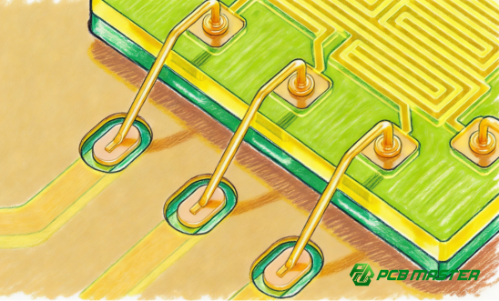
Wire Bonding is a semiconductor packaging process that uses a fine metal wire—typically gold, copper, or aluminum—to connect a chip’s bond pad to a package substrate, lead frame, or PCB pad, creating a direct electrical path.
At a practical level, wire bonding serves three critical functions:
- Creates the electrical connection between the die and the outside circuit
- Completes the internal package interconnect structure
- Directly affects package reliability, including bond strength, contact resistance, and long-term performance under thermal cycling
Although advanced interconnect methods such as flip chip have gained traction, wire bonding is still widely used because it offers:
- Lower cost in many applications
- A highly mature process ecosystem
- Broad equipment availability
- Strong process stability in mass production
It remains especially common in:
- Consumer electronics
- Power devices
- Automotive electronics
- Sensors
- Analog and mixed-signal packaging
How Does Wire Bonding Work?
At its core, wire bonding is a solid-state metal joining process. Unlike soldering, it does not rely on molten solder. Instead, it uses a controlled combination of:
- Force
- Heat
- Ultrasonic energy
These inputs cause the wire and bond pad surfaces to undergo plastic deformation and atomic diffusion, forming a metallurgical bond.
During the bonding process:
- The bonding tool presses the wire onto the pad
- Ultrasonic vibration disrupts oxides and surface contamination
- Heat promotes interdiffusion between clean metal surfaces
In most wire bonding processes, there are two key bond locations:
- First bond: typically formed on the die pad
- Second bond: typically formed on the substrate or PCB pad
If the pad surface is contaminated, oxidized, too rough, or not sufficiently flat, the result can be:
- Weak bond strength
- Bond lift
- Wire breakage
- Poor pull test results
- Elevated contact resistance
So while wire bonding may look like a simple “wire attachment” step, in reality it is a materials + surface condition + energy transfer + mechanical control problem.
What Are the Main Types of Wire Bonding?
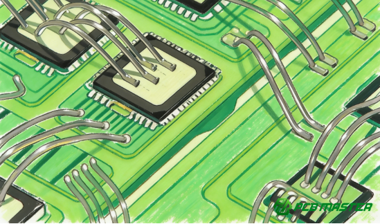
Wire bonding can generally be divided into three main process categories based on how energy is applied:
- Thermo-Compression Bonding
- Thermo-Sonic Bonding
- Ultrasonic Bonding
1) Thermo-Compression Bonding
Thermo-compression bonding uses a heated substrate and applied force to create a solid-state bond through metal deformation and diffusion.
Typical characteristics:
- Substrate temperature is usually high, around 300–400°C
- Relies mainly on heat + pressure
- Does not require ultrasonic energy
- Has a relatively narrow process window
- Slower than mainstream modern bonding methods
- Less common today in high-volume production
While it is no longer the dominant choice in most commercial assembly lines, it still has niche value in certain specialized applications.
2) Thermo-Sonic Bonding
Thermo-sonic bonding is the most widely used wire bonding method today.
It combines:
- Moderate heating (typically 150–250°C)
- Ultrasonic vibration
- Bonding force
Ultrasonic energy breaks through oxides and contamination films, while heat helps drive atomic diffusion. This allows strong and reliable bonding at lower temperatures than thermo-compression bonding.
Key advantages:
- Highly mature and production-proven
- Fast cycle time
- Strong bond integrity
- Good process consistency
- Ideal for gold ball bonding and copper ball bonding
3) Ultrasonic Bonding
Ultrasonic bonding is typically performed at room temperature or low temperature, relying primarily on ultrasonic energy to create the bond.
Typical characteristics:
- Better for temperature-sensitive devices
- Reduces thermal stress on the substrate or package
- Common in aluminum wedge bonding
- More sensitive to surface cleanliness, roughness, and flatness
This method is especially valuable in:
- Power devices
- Automotive electronics
- Packages that cannot tolerate elevated bonding temperatures
Wire Bonding Process Types at a Glance
| Wire Bonding Process | Main Energy Source | Typical Temperature | Common Use Case | Key Advantage | Key Limitation |
| Thermo-Compression Bonding | Heat + Pressure | 300–400°C | Legacy / niche applications | No ultrasonic energy required | Slow, narrow process window |
| Thermo-Sonic Bonding | Heat + Ultrasonic + Pressure | 150–250°C | Mainstream semiconductor packaging | Fast, mature, highly reliable | Requires good thermal stability |
| Ultrasonic Bonding | Ultrasonic + Pressure | Room temp to low temp | Aluminum wedge bonding, heat-sensitive devices | Low thermal stress | More sensitive to surface condition |
What’s the Difference Between Ball Bonding and Wedge Bonding?
In real-world production, the two most common wire bonding formats are:
- Ball Bonding
- Wedge Bonding
The difference between them directly affects:
- Wire material selection
- Bond pad design
- Surface finish requirements
- Throughput and manufacturability
What Is Ball Bonding?
Ball bonding typically uses a capillary tool.
The process flow is usually:
- The wire tip is melted into a ball using EFO (Electronic Flame-Off)
- The first bond is formed on the die pad as a ball bond
- The wire is looped to the substrate or PCB pad
- The second bond is formed as a stitch bond / wedge-shaped second bond
- The wire is broken off, leaving a tail for the next cycle
Key characteristics of ball bonding:
- Fast
- Well-suited for high-volume manufacturing
- Highly mature and widely adopted
- Excellent flexibility across many package types
- Commonly used with gold wire and copper wire
What Is Wedge Bonding?
Wedge bonding uses a wedge tool rather than a capillary.
Unlike ball bonding, wedge bonding does not create a free air ball. Instead, it forms:
- A wedge-shaped first bond
- A wedge-shaped second bond
Key characteristics of wedge bonding:
- Both bond points are wedge-style contacts
- Wire feed and bond orientation are more direction-sensitive
- Better suited for fine pitch applications
- Commonly used with aluminum wire, and sometimes gold wire
- Typically slower than ball bonding
Typical applications include:
- Precision devices
- Power devices
- Automotive electronics
- Aluminum wire interconnects
Ball Bonding vs. Wedge Bonding: Key Differences
| Comparison Factor | Ball Bonding | Wedge Bonding |
| Thickness | ≥0.4mm | 0.05–0.15mm |
| First Bond Shape | Ball bond | Wedge bond |
| Second Bond Shape | Stitch / wedge-style second bond | Wedge bond |
| Typical Speed | Faster | Slower |
| Best for Volume Production | Yes | Less ideal |
| Fine Pitch Capability | Good | Better for tighter pitch |
| Direction Sensitivity | Lower | Higher |
| Common Wire Materials | Gold, Copper | Aluminum, Gold |
| Typical Use Cases | General IC packaging, high-volume assembly | Power devices, fine pitch, precision packages |
How Do You Choose Between Ball Bonding and Wedge Bonding?
As a rule of thumb:
Choose ball bonding when you need:
- High throughput
- Mature process control
- Scalable volume production
Choose wedge bonding when you need:
- Finer pitch capability
- Better suitability for aluminum wire
- More control in power-device or precision applications
What Are the Main Wire Materials Used in Wire Bonding?
The three most common wire materials are:
- Gold wire
- Copper wire
- Aluminum wire
The choice affects not only cost, but also:
- Process stability
- Surface finish compatibility
- Long-term reliability
- Oxidation risk
- Mechanical behavior
1) Gold Wire
Gold wire has long been the most mature and stable wire bonding material.
Advantages:
- Excellent conductivity
- Strong oxidation resistance
- Wide process window
- Proven reliability
Drawback:
- Higher material cost
Common applications:
- Gold ball bonding
- High-reliability packages
- Programs prioritizing process robustness
2) Copper Wire
Copper wire is a major cost-reduction option in modern packaging.
Advantages:
- Lower cost than gold
- Higher mechanical strength
- Strong pull performance
Drawbacks:
- More prone to oxidation
- Requires tighter process and environmental control
- Often improved using PCC (Palladium-Coated Copper)
Common applications:
- Copper ball bonding
- Cost-sensitive high-volume packaging
3) Aluminum Wire
Aluminum wire is especially common in power electronics and automotive applications.
Advantages:
- Lowest material cost
- Well suited for high-current paths
- Mature compatibility with wedge bonding
Drawbacks :
- Oxidation-sensitive
- Can be more vulnerable to fatigue or wire break issues in some conditions
- Highly dependent on surface quality and ultrasonic energy transfer
Common applications:
- Aluminum wedge bonding
- Power modules
- Automotive electronics
Gold vs. Copper vs. Aluminum Wire: Quick Comparison
| Wire Material | Main Advantage | Main Limitation | Most Common Bonding Style | Typical Applications |
| Gold Wire | Best process maturity and oxidation resistance | Higher cost | Ball bonding | High-reliability IC packaging |
| Copper Wire | Lower cost and higher strength | Oxidation sensitivity | Ball bonding | Cost-sensitive mass production |
| Aluminum Wire | Lowest cost, good for high current | More surface-sensitive, can be fatigue-sensitive | Wedge bonding | Power devices, automotive electronics |
Why Is the PCB So Critical to Wire Bonding Success?
A common misconception is that wire bonding is mainly a machine-side process. In production, that’s only half true.
In reality, the PCB (or bonding substrate) is often one of the biggest determinants of yield and consistency because it is not just a landing area—it is the:
- Mechanical support surface
- Metallurgical bonding interface
- Thermal stability platform
If the PCB side is not optimized, even a well-tuned bonder can still produce poor results.
The most important PCB-side factors are:
- Pad design
- Surface finish compatibility
- Surface cleanliness
- Flatness and coplanarity
- Base material and solder mask thermal stability
What Are the Basic PCB Pad Design Requirements for Wire Bonding?
1) The Bond Pad Must Be Larger Than the Bond Footprint
Whether you are using ball bonding or wedge bonding, the bond pad must provide enough real estate for a stable landing zone.
If the pad is too small, you may see:
- Bond placement instability
- Poor second bond formation
- Low pull strength
- Edge stress concentration
2) The Pad Must Be Clearly Defined by Solder Mask Opening
The bonding area typically needs a properly designed solder mask opening so that the bonding tool contacts clean metal—not solder mask encroachment.
3) Solder Mask Must Not Encroach Onto the Bond Pad
If solder mask creeps onto the bond pad, it can cause:
- Uneven bonding force
- Poor ultrasonic energy transfer
- Misformed bond geometry
- Reduced bond strength
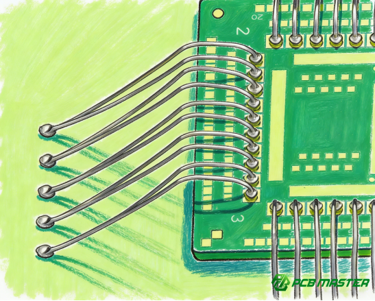
What Does Wire Bonding Require from PCB Cleanliness, Flatness, and Thermal Stability?
These three factors are often the hidden reasons behind unstable bond quality.
1) Surface Cleanliness: It Must Be Extremely Clean
Wire bonding is highly sensitive to contamination. Common contamination sources include:
- Oxides
- Fingerprints
- Flux residue
- Dust particles
- Packaging transfer contamination
These can block metal-to-metal contact and interfere with diffusion, leading to:
- Weak bonds
- Bond lift
- Poor pull test results
- Abnormal contact resistance
2) Flatness and Coplanarity: The Bonding Area Must Be Very Flat
Wire bonding is a precision force-transfer process.
If the PCB has local warpage or height variation, you may see:
- Uneven bonding pressure
- Inconsistent bond formation
- Localized weak bonds
- Increased wire break risk
This is especially critical for wedge bonding, which is generally more sensitive than ball bonding because of its contact geometry.
3) Thermal Stability: Ball Bonding Is Especially Sensitive
For thermo-sonic ball bonding, the PCB often needs to tolerate local temperatures in the 150–250°C range.
If the substrate has low Tg, poor resin stability, or insufficient solder mask heat resistance, the PCB may experience:
- Local deformation
- Warpage
- Dimensional drift
- Solder mask softening or blistering
- Outgassing contamination near the bond area
That is why wire bond-capable PCBs often require:
- High-Tg laminate systems
- High-temperature solder mask
- Stable and consistent surface finishes
Key PCB Requirements for Wire Bonding
| PCB Requirement | Why It Matters | Typical Risk If Not Controlled |
| Pad Size | Ensures sufficient bond landing area | Mis-bond, weak second bond, low pull strength |
| Solder Mask Clearance | Prevents mask interference at the bond site | Poor bond geometry, weak bond |
| Surface Cleanliness | Enables metal-to-metal contact and diffusion | Bond lift, weak bonds, high resistance |
| Flatness / Coplanarity | Ensures uniform bonding force | Inconsistent bonds, wire break risk |
| Surface Roughness Control | Affects ultrasonic energy transfer | Reduced bond strength, unstable wedge bonds |
| Thermal Stability / High Tg | Prevents heat-induced distortion | Warpage, contamination, process drift |
What Surface Finishes Are Best for Gold and Copper Ball Bonding?
Surface finish selection is one of the most critical factors in bond success.
Why Is Soft Gold Usually the Best Choice for Gold Ball Bonding?
For gold wire ball bonding, soft gold is widely considered the preferred and often standard surface finish.
Why?
- Gold-to-gold bonding supports strong atomic diffusion
- Oxidation risk is minimal
- The process is highly mature and consistent in production
To perform well, the gold layer should also be:
- High purity
- Dense and uniform
- Controlled to the right thickness range
If the gold is too thin:
- Bond strength may be weak
- The gold layer may be quickly penetrated
- Underlying metal can affect reliability
If the gold is too thick:
- Cost rises
- Risk of embrittlement-related concerns may increase in some systems
Why Are OSP, Immersion Tin, and Sometimes Immersion Silver Usually Poor Choices for Gold Ball Bonding?
For gold ball bonding, these finishes are generally less desirable because:
- The top layer may not remain stable under heat and ultrasonic energy
- They do not support true gold-to-gold diffusion
- Yield consistency and long-term reliability are usually inferior to soft gold
For high-yield, high-reliability gold wire bonding, they are typically not the first choice.
Why Does Copper Ball Bonding Often Prefer Silver-Based Surfaces?
Copper wire is more oxidation-sensitive than gold, so the bond pad surface must be selected more carefully.
Common preferred directions include:
- Pure silver surfaces
- High-silver palladium-silver type coating
Why these are favored:
- Copper can form a more favorable interfacial system with silver
- Bond consistency can improve
- They can better support copper ball bonding process windows
Recommended Surface Finishes for Ball Bonding
| Bonding Type | Preferred Surface Finish | Why It Works | Common Concerns |
| Gold Ball Bonding | Soft Gold | Best Au-to-Au diffusion, mature process, strong reliability | Gold thickness and purity must be controlled |
| Gold Ball Bonding | ENEPIG / specialized noble metal stacks (when process-qualified) | Can be viable depending on stack design and bonding target | Must validate actual top surface and bondability |
| Gold Ball Bonding | OSP / Immersion Tin / some Immersion Silver | Generally not preferred | Less stable under bonding conditions |
| Copper Ball Bonding | Pure Silver / silver-rich surface systems | Better compatibility with copper bonding interface | Oxidation and storage control are critical |
Editorial note for accuracy in technical publishing:
Surface finish selection for copper ball bonding can vary significantly by package architecture, assembly flow, and supplier qualification. If you’re publishing for an engineering audience, it’s smart to add a line such as:
“Final surface finish selection should always be validated against the bonder process window, wire type (including PCC), and supplier qualification data.”
What Surface Finishes Work Best for Aluminum Wedge Bonding?
For aluminum wedge bonding, one of the most common PCB surface finishes is ENIG (Electroless Nickel Immersion Gold) .
Why Is ENIG Commonly Used for Aluminum Wedge Bonding?
The key point is this:
In many aluminum wedge bonding cases, the nickel layer—not the gold layer—is the true functional bonding interface.
- Nickel layer: provides the main bonding interface and diffusion barrier
- Gold layer: mainly protects the nickel from oxidation before bonding
During wedge bonding, the thin gold layer may be displaced, fractured, or effectively penetrated at the bond interface, allowing the aluminum to interact with the underlying nickel.
This is why aluminum wedge bonding often depends heavily on:
- Nickel layer quality
- Nickel thickness consistency
- Surface roughness control
- Stable gold-over-nickel process quality
Can Aluminum Wire Bond Directly to Immersion Silver or Immersion Tin?
In some lower-demand power-device applications, aluminum wire may be bonded onto:
- Immersion Silver
- Immersion Tin
However, these options typically carry more risk:
- Much tighter cleanliness requirements
- More aggressive oxidation control needed
- Less stable production consistency than ENIG in many cases
From an engineering risk perspective, ENIG is usually the more robust mainstream option.
Recommended Surface Finishes for Aluminum Wedge Bonding
| Bonding Type | Common Surface Finish | Functional Bonding Layer | Key Advantage | Main Risk |
| Aluminum Wedge Bonding | ENIG | Nickel layer | Mature, stable, widely used | Nickel quality must be tightly controlled |
| Aluminum Wedge Bonding | Immersion Silver | Silver surface | Can work in some lower-demand power applications | Oxidation / cleanliness sensitivity |
| Aluminum Wedge Bonding | Immersion Tin | Tin surface | Sometimes used in limited cases | Consistency and bond robustness can be weaker |
How Do PCB Requirements Differ by Wire Bonding Method?
Here’s the short version:
- Ball bonding is more sensitive to surface finish compatibility and thermal stability
- Wedge bonding is more sensitive to flatness, roughness, and ultrasonic energy transfer
- Pure ultrasonic bonding reduces heat demand but increases dependence on surface quality
Thermo-Compression Bonding PCB Priorities
- Higher temperature resistance
- Stronger dimensional stability
- Better mechanical support under pressure
Thermo-Sonic Ball Bonding PCB Priorities
- High-quality noble metal bonding surface (especially soft gold where applicable)
- High-Tg base material
- High-temperature solder mask
- Excellent cleanliness and pad definition
Ultrasonic Aluminum Wedge Bonding PCB Priorities
- Lower heat resistance requirement than thermo-sonic processes
- Higher dependence on:
- Surface flatness
- Surface roughness control
- Cleanliness
- Oxide control
PCB Priorities by Wire Bonding Method
| Bonding Method | Top PCB Priority | Secondary Priority | Common Failure Risk if Mismatched |
| Thermo-Compression | High heat resistance | Dimensional stability | Warpage, poor bond formation |
| Thermo-Sonic Ball Bonding | Surface finish compatibility | High-Tg + clean pad + stable solder mask | Weak bonds, contamination-related lift |
| Ultrasonic Wedge Bonding | Flatness / roughness / cleanliness | Oxide control | Inconsistent ultrasonic coupling, weak wedge bonds |
What Are the Most Common Wire Bonding Failure Modes and How Should You Troubleshoot from the PCB Side?
In many real production environments, wire bonding failures are not caused by the bonder alone. Very often, the PCB or substrate is the root cause.
Common wire bonding failure modes include:
- Bond lift
- Weak bond / low pull strength
- Poor second bond formation
- Wire break
- High contact resistance
- Reliability drift after thermal cycling
Recommended PCB-Side Troubleshooting Sequence
When a wire bonding issue occurs, check in this order:
1) Verify Surface Finish Compatibility
Make sure the selected surface finish actually matches:
- The wire material
- The bonding type (ball vs. wedge)
- The qualified process window
Example: gold ball bonding on an unsuitable OSP-like surface is a common mismatch.
2) Check for Oxidation or Contamination
Review:
- Incoming material handling
- Storage conditions
- Packaging method
- Moisture control
- Fingerprint and touch contamination risk
3) Inspect Pad Design and Solder Mask Registration
Look for:
- Pad too small for the bond footprint
- Insufficient solder mask opening
- Solder mask encroachment
- Irregular pad edge geometry
4) Evaluate Flatness, Coplanarity, and Surface Texture
This is especially important for wedge bonding.
Check for:
- Local warpage
- Height variation
- Rough or inconsistent surface texture
- Uneven plating topography
5) Review Base Material and Solder Mask Thermal Performance
Confirm whether the board is deforming, outgassing, or softening during the bonding thermal cycle.
Wire Bonding Failure Modes and Likely PCB Causes
| Failure Mode | Likely PCB-Side Cause | First Thing to Check |
| Bond Lift | Contamination, oxidation, wrong surface finish | Surface finish + cleanliness |
| Low Pull Strength | Small pad, rough surface, poor finish compatibility | Pad size + surface condition |
| Poor Second Bond | Pad geometry issue, mask encroachment, uneven surface | Pad opening + solder mask alignment |
| Wire Break | Uneven bond formation, excessive stress from poor planarity | Flatness + bond geometry |
| High Contact Resistance | Oxidation, contamination, unstable metallurgical interface | Surface oxidation + finish consistency |
Final Takeaway: Wire Bonding Is Really About Process Matching
From an engineering perspective, wire bonding is not just a machine step—it is a system-level compatibility problem involving:
- Wire material
- Bonding method
- Surface finish
- Pad design
- Surface cleanliness
- Flatness
- Thermal stability
If you only remember five things from this article, make them these:
1. Thermo-sonic bonding is the mainstream wire bonding process today
2. Ball bonding is usually best for high-volume manufacturing, while wedge bonding is often better for fine pitch and aluminum wire applications
3. Gold, copper, and aluminum wire each require different process windows and surface finish strategies
4. The PCB is not just a passive carrier—it is often a primary determinant of bond yield
5. Stable wire bonding yield depends on controlling pad design, surface finish, cleanliness, flatness, and thermal robustness together
In real production, consistent wire bonding performance is rarely achieved by simply tuning parameters after the fact. The best results come from co-designing the bonding process and the PCB structure from the beginning—and ensuring those design requirements can be consistently executed in manufacturing. As wire bonding performance depends heavily on pad design, surface finish, flatness, and material stability, choosing the right PCB supplier is just as important as selecting the right bonding process. PCBMASTER, an experienced PCB manufacturer , provides reliable PCB solutions for demanding semiconductor and electronic applications, with strong capabilities in surface finish control, precision fabrication, and quality consistency to help support stable and dependable wire bonding performance.
FAQ: Common Wire Bonding Questions
1) Is wire bonding the same as standard SMT soldering?
No. Wire bonding is a die-level interconnect process that uses fine metal wire and solid-state bonding. SMT soldering uses solder paste and reflow to attach packaged components to a PCB.
2) Is gold ball bonding always better than copper ball bonding?
Not necessarily. Gold is more oxidation-resistant and generally easier to process, but it costs more. Copper is lower cost and mechanically stronger, but it requires tighter oxidation control and more careful surface finish selection.
3) Why is aluminum wedge bonding so common in power devices?
Because aluminum wire is low cost, suitable for high-current paths, and has a long history of use in wedge bonding for power electronics and automotive-grade applications.
4) What is the most commonly overlooked PCB risk in wire bonding?
The most frequently overlooked issues are usually:
- Surface contamination
- Solder mask encroachment onto bond pads
- Poor flatness
- Oxidation during storage
- Inconsistent surface finish quality from lot to lot
5) What should be checked first when launching a wire bonding project?
Start with these three items first:
- Wire material
- Bonding type (ball or wedge)
- PCB surface finish compatibility
- If those three are mismatched, process tuning alone usually won’t solve the problem.
About the Author

Carol Luo
PCB Design EngineerI'm Carol, a PCB Engineer at PCBMASTER with experience in PCB design and manufacturing engineering since 2018. I focus on translating engineering requirements into reliable PCB solutions, with expertise in stack-up design, material selection, and design-for-manufacturing (DFM). I share practical engineering insights from real-world PCB design and production experience.
Visit Carol Luo's Profile