








Ceramic Capacitor: Types, Working Principles, Applications, and PCB Design Considerations
A ceramic capacitor is a passive electronic component that uses a ceramic dielectric to store and release electrical energy. Ceramic capacitors are widely used in PCB designs for decoupling, filtering, noise suppression, timing, and energy stabilization . Their performance depends on dielectric class, capacitance, voltage rating, package size, DC bias characteristics, temperature stability, and PCB layout. For engineers selecting or manufacturing PCB assemblies, understanding these parameters is essential for achieving reliable electrical performance.
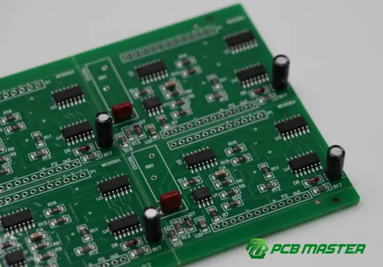
What Is a Ceramic Capacitor?
A ceramic capacitor is a capacitor that uses ceramic material as its dielectric layer between conductive electrodes. It is one of the most widely used capacitor technologies in modern electronics because it can provide high-frequency performance, compact dimensions, and relatively low equivalent series resistance (ESR) .
A typical ceramic capacitor consists of:
- Ceramic dielectric
- Internal metal electrodes
- External terminations
- Protective outer structure
For surface-mount applications, the most common form is the multilayer ceramic capacitor (MLCC) . An MLCC contains multiple alternating ceramic dielectric and electrode layers connected to opposing external terminals.
The basic capacitance relationship is:
C = εA / d
where:
- C = capacitance
- ε = dielectric permittivity
- A = effective electrode area
- d = dielectric thickness
Increasing the effective electrode area or dielectric permittivity, or reducing dielectric thickness, allows manufacturers to achieve higher capacitance within a small package.
How Does a Ceramic Capacitor Work?
A capacitor stores electrical energy in an electric field created between its electrodes.
When voltage is applied, electric charge accumulates on the electrodes. When the circuit requires current, the capacitor can release stored energy.
In practical PCB circuits, ceramic capacitors are frequently used to:
- Stabilize supply voltage
- Suppress high-frequency noise
- Filter unwanted AC components
- Decouple integrated circuits from power rails
- Reduce voltage fluctuations
- Support transient current demand
For example, a small MLCC placed close to an IC's power and ground pins can provide a low-impedance path for high-frequency transient currents.
This is why component selection and PCB placement are closely related . A theoretically suitable capacitor can still perform poorly if the PCB layout introduces excessive parasitic inductance.
What Are the Main Types of Ceramic Capacitors?
Ceramic capacitors can be classified according to their dielectric characteristics and construction.
Class 1 Ceramic Capacitors
Class 1 dielectrics, such as C0G/NP0 , provide excellent electrical stability.
Typical characteristics include:
- Low temperature coefficient
- High stability
- Low dielectric loss
- Good frequency characteristics
- Relatively low capacitance density
They are commonly used in:
- RF circuits
- Oscillators
- Precision timing circuits
- Filters
- Signal-processing circuits
For applications where capacitance stability is more important than maximum capacitance, C0G/NP0 is often an attractive choice.
Class 2 Ceramic Capacitors
Class 2 dielectrics include materials such as X7R, X5R, and Y5V .
They generally offer much higher capacitance per unit volume than Class 1 ceramics.
Common applications include:
- Power-supply decoupling
- DC/DC converters
- Microcontroller circuits
- Digital ICs
- Automotive electronics
- Consumer electronics
However, Class 2 capacitors exhibit stronger capacitance variation caused by factors such as DC bias, temperature, and aging .
C0G vs. X7R vs. X5R: What Is the Difference?
The dielectric designation provides important information about temperature characteristics.
| Dielectric | Temperature Characteristics | Stability | Typical Applications |
|---|---|---|---|
| C0G / NP0 | Very stable | Excellent | RF, precision circuits, filters |
| X7R | Approximately −55°C to +125°C | Good | Decoupling, automotive, power |
| X5R | Approximately −55°C to +85°C | Good | General-purpose decoupling |
| Y5V | Wider capacitance variation | Lower | Cost-sensitive applications |
The dielectric should therefore be selected based on the electrical requirements rather than simply choosing the capacitor with the highest nominal capacitance.
A 10 µF capacitor does not necessarily behave like an ideal 10 µF capacitor under every operating condition.
What Is an MLCC?
An MLCC, or Multilayer Ceramic Capacitor , is the dominant ceramic capacitor technology used in compact electronic products.
Its internal structure consists of many alternating dielectric and electrode layers. Increasing the number of active layers increases the effective electrode area and therefore increases capacitance without requiring a proportionally larger component footprint.
MLCCs are particularly valuable for PCB applications because they combine:
- Small package sizes
- High capacitance density
- Low ESR
- Good high-frequency performance
- Surface-mount compatibility
- High-volume manufacturability
They are found in everything from smartphones and computers to industrial equipment, automotive electronics, communications equipment, and power-management systems.
Why Are Ceramic Capacitors Important in PCB Design?
Ceramic capacitors are not simply passive components that can be placed anywhere on a PCB.
Their electrical effectiveness is strongly influenced by PCB layout .
Decoupling and Bypass
A decoupling capacitor is typically positioned close to an IC's power pins.
Its purpose is to provide a local source of transient current and reduce high-frequency voltage fluctuations on the power rail.
The shorter the current path between the capacitor and the IC, the lower the parasitic inductance can generally be.
Power-Supply Filtering
Ceramic capacitors can work with inductors, resistors, and other capacitors to form filtering networks.
For example, a power-management circuit may use different capacitor values to address different frequency ranges.
High-Frequency Applications
Ceramic capacitors, particularly low-loss Class 1 devices, are widely used in high-frequency circuits because of their favorable RF characteristics.
However, designers should consider:
- Self-resonant frequency
- ESR
- ESL
- Package geometry
- PCB trace length
- Ground-plane configuration
What Is DC Bias in Ceramic Capacitors?
One of the most important characteristics of Class 2 ceramic capacitors is DC bias .
When a DC voltage is applied to an X5R or X7R MLCC, its effective capacitance can decrease significantly from the nominal value.
For example, a capacitor marked with a particular capacitance value may provide substantially less effective capacitance when operating near its rated voltage.
Therefore, selecting an MLCC based only on its printed capacitance can result in an inaccurate design.
Engineers should evaluate the capacitor's effective capacitance under actual operating voltage and temperature conditions .
This is particularly important in:
- DC/DC converters
- Battery-management systems
- Automotive electronics
- Power modules
- High-current digital systems
How Should You Choose a Ceramic Capacitor?
A practical selection process should consider several parameters simultaneously.
1. Capacitance
Determine the required capacitance based on the circuit function.
Decoupling applications may require multiple capacitor values rather than one universal value.
2. Rated Voltage
The capacitor's rated voltage should exceed the maximum expected operating voltage with an appropriate design margin.
For Class 2 MLCCs, also consider capacitance loss under DC bias .
3. Dielectric
Choose the dielectric according to stability requirements.
- C0G/NP0: precision and RF applications
- X7R: stable general-purpose and automotive applications
- X5R: compact consumer and general electronics
- Y5V: applications where large capacitance variation is acceptable
4. Package Size
Common MLCC package sizes include:
- 0201
- 0402
- 0603
- 0805
- 1206
Smaller packages can reduce PCB area, but mechanical reliability and electrical characteristics must also be considered.
5. Temperature
The operating environment can substantially affect capacitor performance.
Automotive, industrial, and outdoor electronics may require significantly greater temperature stability than typical consumer products.
6. Mechanical Reliability
MLCCs are ceramic components and can be vulnerable to mechanical stress.
PCB designers should consider:
- Board flexing
- Component placement
- Solder-joint stress
- Depanelization methods
- Mounting conditions
For applications exposed to mechanical stress, specialized MLCC structures or alternative capacitor technologies may be appropriate.
Common Ceramic Capacitor Selection Mistakes
Mistake 1: Choosing Only by Nominal Capacitance
A capacitor labeled "10 µF" does not necessarily maintain 10 µF under actual operating conditions.
DC bias, temperature, frequency, and aging can all affect effective capacitance.
Mistake 2: Ignoring Voltage Derating
Operating too close to the rated voltage can reduce reliability and, depending on the dielectric, substantially affect effective capacitance.
Mistake 3: Using an Inappropriate Dielectric
Selecting Y5V when a precision or stable capacitance is required can create unacceptable circuit variation.
Mistake 4: Placing Decoupling Capacitors Too Far Away
Even when the capacitance is correct, excessive PCB trace length can introduce parasitic inductance.
For high-frequency decoupling, placement and current-loop geometry are part of the capacitor's effective performance .
Mistake 5: Ignoring PCB Assembly Conditions
Small MLCCs are sensitive to manufacturing and mechanical conditions. PCB assembly parameters, board handling, soldering, and depanelization can influence component reliability.
Ceramic Capacitors in PCB Manufacturing and PCBA
The performance of a ceramic capacitor depends not only on the component itself but also on how it is integrated into the PCB and assembled.
For PCBA manufacturers, important considerations include:
- Component placement accuracy
- Solder paste printing
- Pick-and-place accuracy
- Reflow profile
- AOI inspection
- Component orientation
- Solder-joint quality
- PCB warpage
- Trace and pad design
A reliable PCBA process therefore requires coordination between PCB design, component selection, SMT process engineering, and quality inspection .
Ceramic Capacitor vs. Other Capacitor Technologies
Ceramic capacitors are not universally superior to every other capacitor type. Different technologies serve different engineering requirements.
| Characteristic | Ceramic | Aluminum Electrolytic | Tantalum | Film |
|---|---|---|---|---|
| Size | Small | Larger | Small/medium | Larger |
| ESR | Generally low | Generally higher | Low/moderate | Very low |
| High-frequency performance | Excellent | More limited | Good | Good |
| High capacitance | Excellent for MLCCs | Excellent | Good | Limited by size |
| Polarity | Non-polarized | Polarized | Usually polarized | Non-polarized |
| Typical use | Decoupling, filtering, RF | Bulk energy storage | Compact power filtering | Precision/power applications |
The appropriate capacitor technology depends on the application's voltage, capacitance, frequency, temperature, reliability, physical dimensions, and cost requirements.
PCBMASTER's Approach to PCB and PCBA Applications
For projects that integrate ceramic capacitors into PCB assemblies, the component itself is only one part of the engineering equation.
PCBMASTER provides PCB, PCBA, and SMT manufacturing , supporting applications ranging from prototypes to volume production.
Its manufacturing capabilities cover HDI , high-frequency PCB , FPC , rigid-flex PCB , metal-core PCB , and conventional multilayer boards , allowing capacitor selection and PCB construction to be considered together rather than as isolated processes.
PCBMASTER also provides free engineering file checking , allowing potential manufacturability, performance, and cost issues to be identified before production. This can be particularly useful when PCB designs contain dense SMT components, fine-pitch packages, or demanding power-management circuits.
For quality-sensitive applications, PCBMASTER operates under ISO 9001 and IATF 16949 quality management systems and provides UL-certified products. Boards undergo quality inspection and testing before shipment.
Practical Checklist for Ceramic Capacitor Selection
Before releasing a PCB design for production, engineers can verify the following:
| Checkpoint | Key Question |
|---|---|
| Capacitance | Is the required effective capacitance achieved under operating conditions? |
| Dielectric | Is C0G, X7R, X5R, or another dielectric appropriate? |
| Voltage | Is there sufficient voltage margin? |
| DC Bias | Has capacitance reduction under DC voltage been evaluated? |
| Temperature | Does the capacitor meet the application's temperature range? |
| Package | Is the package compatible with PCB space and assembly requirements? |
| Placement | Is the capacitor sufficiently close to the relevant power or signal node? |
| Mechanical Stress | Could PCB bending or depanelization damage the MLCC? |
| SMT Process | Is the component compatible with the intended assembly process? |
| Reliability | Does the component meet the application's reliability requirements? |
Summary: What Matters Most When Using Ceramic Capacitors?
Ceramic capacitors are fundamental components in modern PCB and PCBA designs, but nominal capacitance alone is not enough to determine whether a capacitor is suitable .
Engineers should evaluate the complete electrical and mechanical environment, including dielectric type, DC bias, voltage rating, temperature, package size, ESR/ESL, placement, and PCB assembly conditions .
For simple decoupling applications, X5R and X7R MLCCs are widely used. For precision and RF applications, C0G/NP0 can provide superior stability. In demanding PCB assemblies, however, the component selection must also be considered together with PCB layout, manufacturing tolerances, SMT processing, and quality control .
As electronic systems become smaller, faster, and more power-dense, ceramic capacitors will continue to play a critical role in power integrity, signal integrity, noise control, and circuit reliability .
The most effective approach is therefore not simply to ask, “What capacitance do I need?” but rather, “What capacitance will the circuit actually have under its real operating conditions?”
Tags: #CeramicCapacitor #MLCC #Capacitor #PCB #PCBA #SMT #PCBDesign #Electronics #CircuitDesign #PowerIntegrity #PCBManufacturing #PCBMASTER
About the Author

Carol Luo
PCB Design EngineerI'm Carol, a PCB Engineer at PCBMASTER with experience in PCB design and manufacturing engineering since 2018. I focus on translating engineering requirements into reliable PCB solutions, with expertise in stack-up design, material selection, and design-for-manufacturing (DFM). I share practical engineering insights from real-world PCB design and production experience.
Visit Carol Luo's Profile

