








Electrolytic Capacitor Electrolyte: Composition, Function, Types, and Its Impact on PCB Reliability
Electrolytic capacitor electrolyte is the electrically conductive medium that enables an electrolytic capacitor to form and maintain its oxide dielectric layer. Its chemical composition strongly affects capacitance, leakage current, ESR, ripple-current capability, temperature stability, lifetime, and failure behavior. Understanding electrolyte chemistry is therefore important not only for capacitor selection but also for reliable PCB and PCBA design, particularly in power supplies, industrial electronics, automotive electronics, and other high-reliability applications.
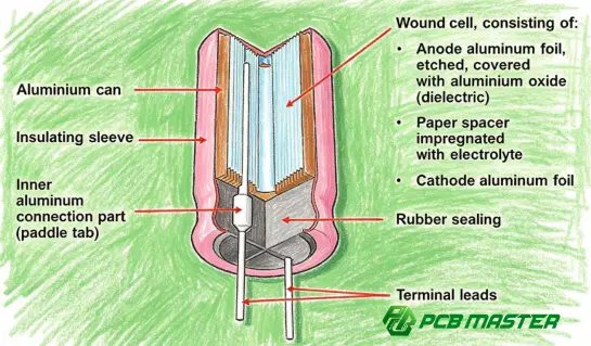
What Is Electrolytic Capacitor Electrolyte?
An electrolytic capacitor electrolyte is a conductive chemical system inside an electrolytic capacitor that works together with the anode, cathode, and dielectric oxide layer to provide capacitance.
Unlike the dielectric material in a ceramic capacitor, an electrolytic capacitor typically uses an extremely thin oxide layer formed on the anode foil as its dielectric. The electrolyte serves as the electrical connection to the cathode system and helps maintain the oxide layer during normal operation.
The electrolyte therefore plays a fundamental role in the capacitor's electrical and thermal characteristics.
A simplified structure can be represented as:
Anode foil → oxide dielectric → electrolyte → cathode foil
The extremely thin oxide dielectric enables electrolytic capacitors to achieve relatively high capacitance in a compact package.
Why Is the Electrolyte Important?
The electrolyte influences several important capacitor parameters:
- Capacitance stability
- Equivalent Series Resistance (ESR)
- Leakage current
- Ripple-current capability
- Operating-temperature range
- Shelf life
- Electrical lifetime
- Self-healing and oxide-layer stability
- Failure behavior
For PCB designers, this means that electrolyte selection is not simply a component-manufacturing detail. It can directly affect the reliability of the finished electronic assembly.
What Is Electrolytic Capacitor Electrolyte Made Of?
There is no single electrolyte formulation used in all electrolytic capacitors. Different capacitor technologies use different electrolyte systems.
Traditional aluminum electrolytic capacitors commonly use a liquid electrolyte , while newer designs may use polymer-based or hybrid electrolyte systems .
Typical electrolyte systems can contain combinations of:
| Electrolyte System | Typical Characteristics | Common Application |
|---|---|---|
| Liquid electrolyte | Mature technology, high capacitance, broad availability | Power supplies, general electronics |
| Polymer electrolyte | Very low ESR and strong high-frequency performance | DC/DC converters, computing, automotive electronics |
| Hybrid electrolyte | Combines liquid and conductive polymer characteristics | High-reliability power applications |
| Solid electrolyte systems | Stable electrical characteristics and low impedance | Compact, high-performance electronics |
The exact chemical formulation is normally proprietary to the capacitor manufacturer. It may include a solvent, conductive salt, additives, and other components designed to control conductivity, corrosion, gas generation, and oxide stability.
How Does Electrolyte Work Inside an Electrolytic Capacitor?
The electrolyte's role becomes clearer by looking at how an aluminum electrolytic capacitor operates.
1. Formation of the Oxide Dielectric
During capacitor manufacturing, a controlled electrochemical process forms an aluminum oxide layer on the anode foil.
This oxide acts as the dielectric.
Because the oxide layer is extremely thin, the capacitor can achieve high capacitance relative to its physical size.
2. Electrolyte Provides the Cathodic Connection
The electrolyte is electrically conductive and contacts the dielectric surface through the capacitor's internal construction.
It effectively forms part of the cathode system.
This allows the capacitor to store electrical energy while maintaining the insulating oxide layer between the anode and electrolyte.
3. Electrolyte Helps Maintain the Dielectric
During operation, small imperfections or chemical changes can affect the oxide layer.
The electrolyte participates in processes that help maintain or reform the dielectric under appropriate operating conditions.
This is one reason why the electrolyte's chemical properties have a direct relationship with capacitor lifetime and reliability.
Liquid Electrolyte vs. Polymer Electrolyte
One of the most important distinctions when selecting electrolytic capacitors is whether the capacitor uses a conventional liquid electrolyte or a conductive polymer system.
| Characteristic | Liquid Electrolytic | Polymer Electrolytic |
|---|---|---|
| Electrolyte state | Liquid | Solid/conductive polymer |
| ESR | Generally higher | Generally very low |
| High-frequency performance | Moderate | Excellent |
| Ripple-current capability | Application-dependent | Generally strong |
| Dry-out mechanism | Important consideration | Significantly different |
| Capacitance density | High | High |
| Typical applications | General power electronics | High-performance power circuits |
The choice should be based on the electrical and environmental requirements of the application rather than capacitance alone.
For example, a capacitor with the correct capacitance but inadequate ripple-current capability can experience excessive internal heating and reduced service life.
How Electrolyte Affects ESR and Ripple Current
ESR is one of the most important parameters influenced by electrolyte characteristics.
When ripple current flows through a capacitor, power is dissipated internally:
P loss =I 2 RMS ×ESR
This means that even a relatively small increase in ESR can significantly increase internal heat generation when RMS ripple current is high.
For a PCB power-supply designer, this has practical consequences.
A capacitor used for:
- DC-link filtering
- Output filtering
- Switching power supplies
- Motor drives
- Automotive power electronics
- Industrial power conversion
may experience substantial ripple current.
If its ESR is too high, the resulting temperature rise can accelerate degradation of the electrolyte and other internal materials.
The Thermal Connection
Capacitor lifetime is strongly related to operating temperature.
As the internal temperature increases, chemical degradation processes generally accelerate. For liquid-electrolyte aluminum capacitors, electrolyte evaporation and related changes can eventually increase ESR and reduce capacitance.
This creates a potentially unfavorable cycle:
Higher ESR → higher internal losses → higher temperature → electrolyte degradation → even higher ESR
Proper capacitor selection and thermal PCB design are therefore closely connected.
What Happens When Electrolytic Capacitor Electrolyte Dries Out?
Electrolyte dry-out is a well-known aging mechanism in conventional aluminum electrolytic capacitors.
As electrolyte is gradually lost or chemically altered, the capacitor's electrical characteristics can deteriorate.
Typical symptoms include:
- Increasing ESR
- Decreasing capacitance
- Increasing ripple-voltage stress
- Increased self-heating
- Reduced filtering performance
- Possible bulging or vent activation in severe cases
- Eventual capacitor failure
However, not every electrolytic capacitor failure is caused by electrolyte dry-out.
Other mechanisms can include:
- Excessive voltage
- Reverse voltage
- Excessive ripple current
- High ambient temperature
- Internal gas generation
- Seal degradation
- Manufacturing defects
- Mechanical or thermal stress
Therefore, diagnosing an electrolytic capacitor failure requires looking at the electrical and environmental conditions rather than assuming that the electrolyte simply "dried out."
Why Electrolytic Capacitor Electrolyte Matters for PCB Design
The capacitor itself may be manufactured correctly, but its performance can still be compromised if the PCB design does not account for its operating conditions.
Power Integrity
Electrolytic capacitors are frequently used as bulk energy-storage and filtering components.
Their capacitance and ESR affect:
- DC rail stability
- Transient response
- Ripple voltage
- Converter output quality
- Low-frequency filtering
When combined with ceramic capacitors, electrolytics can provide bulk capacitance while MLCCs handle higher-frequency components.
Thermal Management
A PCB designer should consider:
ambient temperature + capacitor self-heating + nearby heat sources
when determining whether an electrolytic capacitor is suitable.
Avoid placing temperature-sensitive electrolytic capacitors unnecessarily close to:
- Power MOSFETs
- Transformers
- Inductors
- Power resistors
- Heat sinks
- High-current traces
- Other major heat-generating components
Polarity
Standard aluminum electrolytic capacitors are polarized.
Incorrect polarity can cause excessive current and potentially severe capacitor failure.
PCB footprints, silkscreen markings, assembly documentation, and automated inspection should therefore clearly identify polarity.
Common Mistakes When Selecting Electrolytic Capacitors
Choosing Only by Capacitance
A common mistake is selecting a capacitor based only on:
Voltage + capacitance + package size
A more complete evaluation should include:
- Rated voltage
- Capacitance tolerance
- ESR
- Ripple-current rating
- Operating temperature
- Lifetime rating
- Impedance
- Frequency characteristics
- Polarity
- Physical dimensions
- Mounting requirements
Ignoring Ripple Current
A capacitor may have the correct capacitance but still be unsuitable for a switching converter if its ripple-current rating is inadequate.
Ripple current should be evaluated alongside ESR and thermal conditions.
Ignoring Temperature
A capacitor rated for a particular lifetime at one temperature does not necessarily provide the same lifetime under a significantly hotter operating environment.
Temperature rating and lifetime specification should therefore be evaluated together.
Replacing a Capacitor With a Different Electrolyte Technology Without Verification
Replacing a liquid-electrolyte capacitor with a polymer capacitor—or vice versa—may change ESR, ripple current, impedance, leakage current, and transient behavior.
A replacement should therefore be electrically validated rather than selected solely according to capacitance and voltage.
Electrolytic Capacitor Electrolyte and PCB Reliability
For high-reliability electronics, capacitor selection should be integrated into the broader PCB and PCBA engineering process.
A reliable workflow includes:
- Define electrical requirements
- Calculate capacitance and ripple-current requirements
- Evaluate ESR and impedance
- Check temperature conditions
- Verify capacitor lifetime
- Review PCB placement and thermal environment
- Confirm polarity and footprint
- Perform engineering file review
- Validate the assembled board
- Conduct appropriate electrical and reliability testing
How PCB Manufacturing Quality Can Influence Capacitor Reliability
Component selection is only one part of the reliability equation. The PCB and PCBA manufacturing process also affects the final assembly.
For example, manufacturing engineers should consider:
- Component footprint accuracy
- Polarity marking
- Soldering temperature profile
- Thermal exposure during assembly
- Inspection coverage
- Board-level electrical testing
- Mechanical stress during handling
- Component sourcing consistency
For complex electronic products, engineering file review before production can identify potential manufacturability and assembly problems before they become production issues.
This is particularly relevant for automotive electronics, industrial control systems, communications equipment, and other applications where component reliability directly affects system availability.
PCBMASTER's Approach to Reliable PCB and PCBA Production
As a PCB and PCBA manufacturer serving applications across multiple industries, PCBMASTER integrates PCB manufacturing, assembly, engineering review, and quality control into a one-stop production process.
Its quality system includes ISO 9001, IATF 16949, UL Certification, and RoHS compliance , supporting applications where controlled manufacturing and traceable quality requirements are important.
PCBMASTER also provides free engineering file checking , allowing engineers to review manufacturability, PCB performance considerations, and potential cost or production issues before manufacturing.
For projects involving power electronics and electrolytic capacitors, this type of engineering review can be valuable because component selection, PCB layout, thermal conditions, and assembly requirements need to work together rather than being evaluated independently.
The company operates an 80,000 m² factory and provides PCB, PCBA, SMT, component sourcing, and design-support services, covering prototypes through higher-volume production.
Practical Checklist for Selecting an Electrolytic Capacitor
Before approving an electrolytic capacitor for a PCB design, check:
| Parameter | What to Verify | Why It Matters |
|---|---|---|
| Capacitance | Required capacitance and tolerance | Determines energy storage/filtering |
| Rated voltage | Adequate voltage margin | Prevents dielectric overstress |
| ESR | Required impedance/ESR | Affects losses and ripple |
| Ripple current | RMS ripple-current rating | Determines self-heating |
| Temperature | Maximum operating temperature | Strongly affects lifetime |
| Lifetime | Manufacturer-rated endurance | Indicates expected service life |
| Electrolyte technology | Liquid, polymer, hybrid, etc. | Changes electrical and aging behavior |
| Polarity | Correct PCB orientation | Prevents catastrophic misuse |
| Package | Diameter, height, footprint | Ensures mechanical compatibility |
| Application | Power, automotive, industrial, etc. | Determines reliability requirements |
Summary
Electrolytic capacitor electrolyte is a critical part of the capacitor's electrical and reliability characteristics. It works with the anode oxide dielectric and cathode system to enable high capacitance, while its composition and physical properties influence ESR, leakage current, ripple-current capability, temperature performance, and service life.
For PCB designers, the key lesson is simple: do not select an electrolytic capacitor based on capacitance and voltage alone. Electrolyte technology, ESR, ripple current, temperature, lifetime, PCB thermal conditions, and assembly requirements should all be evaluated together.
As electronic systems become more power-dense, especially in automotive electronics, industrial control, communications, and power-conversion applications, understanding the interaction between electrolyte chemistry, capacitor behavior, PCB design, and manufacturing quality becomes increasingly important.
Tags: #ElectrolyticCapacitor #Electrolyte #Capacitor #PCB #PCBA #ElectronicsEngineering #PowerElectronics #PCBDesign #SMT #PCBManufacturing #PCBMASTER#ElectronicsInsights
About the Author

Carol Luo
PCB Design EngineerI'm Carol, a PCB Engineer at PCBMASTER with experience in PCB design and manufacturing engineering since 2018. I focus on translating engineering requirements into reliable PCB solutions, with expertise in stack-up design, material selection, and design-for-manufacturing (DFM). I share practical engineering insights from real-world PCB design and production experience.
Visit Carol Luo's Profile

