








Custom Rigid PCB Manufacturer
for Prototypes & Production
Build Rigid PCBs to your required specifications with engineering support, stable material supply, and advanced manufacturing capabilities.
- 1–4 Layer Quick-Turn Rigid PCB Prototypes
- Multilayer, HDI, High-Speed & High-Frequency Rigid PCB
- Stable Material Supply & Consistent PCB Manufacturing
- Custom Rigid PCB Fabrication from Prototype to Production
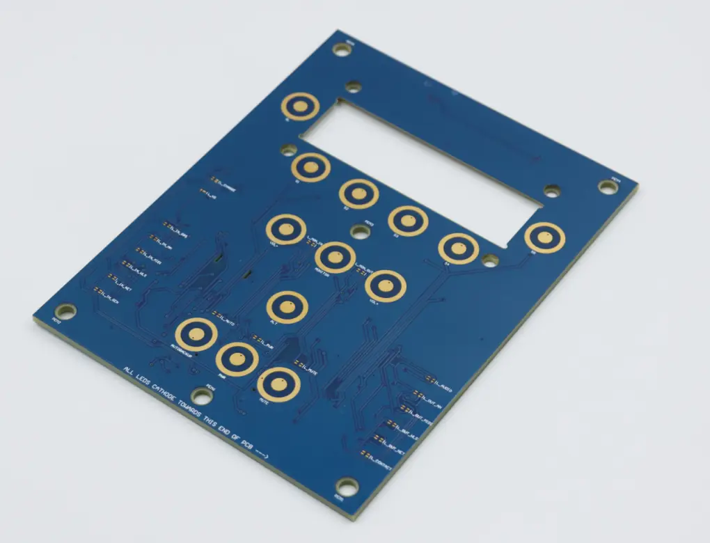


Why Choose PCBMASTER for Rigid PCB Manufacturing?
When choosing a Rigid PCB manufacturer, you need more than competitive pricing. You need fast delivery, stable materials, reliable quality, and the engineering expertise to support your project. PCBMASTER provides quick-turn Rigid PCB manufacturing for 1–4 layer prototypes, as well as multilayer, HDI, high-speed, and high-frequency Rigid PCB solutions.
Engineering Support
Stable material supply and engineering support help reduce manufacturing risks. PCBMASTER provides Gerber review, DFM, stack-up, and material selection support before Rigid PCB manufacturing, so potential design and production issues can be identified earlier.
Quality & Compliance
PCBMASTER operates its Rigid PCB manufacturing under ISO 9001 and IATF 16949 quality management systems, with RoHS compliance, UL certification, and comprehensive inspection and electrical testing.
Integrated Services
From prototype fabrication to volume production and PCBA, you can work with one manufacturing partner throughout your project lifecycle, reducing handoffs and keeping engineering information consistent.
What Is a Rigid PCB?
A Rigid PCB is a circuit board built on a solid, non-flexible substrate that provides stable mechanical support for components and circuits. Unlike an FPC, a Rigid PCB maintains its shape during installation and operation, while a Rigid-Flex PCB combines rigid and flexible sections for space-constrained designs.
The Rigid PCB manufacturing process typically follows a controlled sequence: Design Files → Engineering Review → Material Preparation → Inner Layer → Lamination → Drilling → Plating → Imaging → Etching → Surface Finish → Routing → Inspection → Testing → Packaging. Each step helps ensure the required electrical and mechanical performance of the finished Rigid PCB.
Because of its mechanical and dimensional stability, a Rigid PCB is suitable for applications requiring reliable component mounting and consistent board geometry. Moreover, Rigid PCB manufacturing supports multilayer structures, high component density, high-speed signal routing, thermal management, and long-term reliability while maintaining cost efficiency.
For your project, PCBMASTER can support the complete Rigid PCB workflow, from PCB design support → Rigid PCB fabrication → PCBA → testing → production, helping you move efficiently from prototype to production with fewer supplier handoffs.
Get a Rigid PCB QuoteRigid PCB Manufacturing Flow
14 Steps- 01 Design Files
- 02 Engineering Review
- 03 Material Preparation
- 04 Inner Layer
- 05 Lamination
- 06 Drilling
- 07 Plating
- 08 Imaging
- 09 Etching
- 10 Surface Finish
- 11 Routing
- 12 Inspection
- 13 Testing
- 14 Packaging
Key Rigid PCB Features for Reliable Electronics
PCBMASTER Rigid PCB solutions are built around a solid structure and stable physical characteristics, giving you a dependable foundation for component mounting, circuit routing, and assembly.
| Feature | Description |
|---|---|
| Maintain Stable Board Shape | Maintains its shape during assembly and operation, providing stable support for components. |
| Achieve Consistent Component Placement | Provides a stable surface for component placement, helping improve assembly accuracy and consistency. |
| Simplify Mechanical Integration | Keeps the designed board shape and dimensions, making installation and enclosure integration easier. |
| Protect Components During Handling | Provides structural strength, helping protect circuits and components during handling and normal operation. |
| Support Reliable Signal & Power Routing | Form reliable conductive paths for power and signals, supporting different circuit requirements. |
| Prevent Unwanted Electrical Connections | Electrically separates conductive layers, helping prevent unwanted connections in multilayer Rigid PCB designs. |
| Enable Multilayer Circuit Connections | Connect different circuit layers, giving you more routing options within the Rigid PCB. |
| Ensure Stable Long-Term Form | Retains its designed physical form, making it suitable for products requiring a stable, non-flexible circuit board. |
Rigid PCB Types for Different Design and Production Requirements
PCBMASTER provides a broad range of Rigid PCB types to match different circuit densities, electrical requirements, thermal conditions, and application needs.
Multilayer Rigid PCB
Uses multiple circuit layers to increase routing capacity, helping you fit complex circuits into a more compact board.
HDI Rigid PCB
Uses high-density interconnections to support finer routing and smaller designs, helping you achieve greater circuit density in limited space.
High-Speed Rigid PCB
Supports controlled-impedance and high-speed signal requirements, helping you maintain signal quality in demanding digital systems.
High-Frequency Rigid PCB
Uses suitable low-loss materials for RF and high-frequency circuits, helping you achieve more stable electrical performance at higher frequencies.
High-Tg Rigid PCB
Provides greater thermal stability than standard materials, making it suitable for Rigid PCB applications exposed to higher operating temperatures.
Heavy Copper Rigid PCB
Uses increased copper thickness to support higher current loads, helping you handle demanding power distribution and power electronics applications.
Metal Core PCB
Uses a metal core to improve heat transfer, helping you manage thermal loads in LED, power, and other heat-generating electronics.
Automotive Rigid PCB
Designed for demanding automotive electronic systems, helping you meet the mechanical, electrical, and reliability requirements of vehicle applications.
Power Rigid PCB
Supports high-current distribution and power conversion circuits, helping you manage electrical loads reliably in power electronics.
Rigid PCB Specifications You Can Customize
PCBMASTER supports a wide range of Rigid PCB specifications, allowing you to customize board structure, materials, dimensions, copper thickness, interconnection technology, and other manufacturing requirements according to your design.
| Rigid PCB Parameter | PCBMASTER Capability / Options |
|---|---|
| PCB Type | Single-Sided / Double-Sided / Multilayer Rigid PCB |
| Layer Count | 1–64 Layers |
| Material | FR-4 / High-Tg / High-Speed / High-Frequency / Aluminum / Ceramic / Specialty Materials |
| Board Thickness | Custom according to project requirements |
| Copper Thickness | Standard / Heavy Copper / Custom |
| Minimum Trace / Space | Down to 2.0 / 2.0 mil |
| Minimum Laser Hole | Down to 0.05 mm |
| High-Aspect-Ratio Drilling | Up to 16:1 |
| Via Type | Through-Hole / Blind / Buried / Microvia |
| Surface Finish | HASL / ENIG / OSP / Other Available Finishes |
| Solder Mask | Green / Black / Blue / Red / Other Options |
| Silkscreen | White / Black / Custom |
| Impedance | Controlled Impedance |
| Special Processes | HDI / Backdrilling / Heavy Copper / Hybrid Lamination |
| Material Supply | Multiple Material Options and Suppliers for Specialized Rigid PCB Requirements |
Where Are Rigid PCBs Used?
PCBMASTER provides Rigid PCB solutions for diverse industries where stable mechanical structure, reliable circuit connections, power distribution, and consistent electrical performance are essential.
Automotive Electronics
Provides the circuit platform for BMS, ECUs, vehicle control units, and other automotive electronics, supporting reliable signal transmission, power distribution, and component mounting.
Industrial Control
Connects controllers, sensors, motors, and communication interfaces in PLCs and automation equipment, providing stable circuits for continuous industrial operation.
AI & Data Center
Supports high-density circuit routing and high-speed signal transmission in servers, accelerators, storage systems, and networking equipment, helping integrate complex computing hardware.
Telecommunications
Carries high-speed signal paths and power connections in routers, switches, base stations, and communication equipment, supporting reliable data transmission.
Consumer Electronics
Serves as the main circuit platform for smart devices, home electronics, and other products, providing stable component mounting and electrical connections within compact designs.
Power Electronics
Provides high-current circuit paths and power distribution in power supplies, converters, inverters, and related equipment, supporting reliable power transmission and conversion.
Medical Electronics
Connects electronic components and functional circuits in diagnostic, monitoring, and medical equipment, providing stable electrical performance for precision electronic systems.
LED & Lighting
Provides circuit connectivity and component support in LED lighting systems, while Metal Core PCB solutions can improve heat transfer from LEDs and other heat-generating components.
From Rigid PCB Design to Manufacturable Boards
Engineering review, DFM support, and Rigid PCB fabrication help ensure your design is ready for reliable production.
Rigid PCB Manufacturing Capability at PCBMASTER
PCBMASTER combines quick-turn prototyping, advanced Rigid PCB manufacturing technologies, and scalable production capacity to support different project requirements.
| Capability | PCBMASTER Capacity | What It Means for Your Rigid PCB Project |
|---|---|---|
| 1–4 Layer Quick-Turn PCB Prototype | Quick Turn | Accelerates Rigid PCB prototype development for early-stage testing and product validation. |
| High-Frequency PCB | 30,000 m2/Month | Supports Rigid PCB applications requiring high-frequency materials and demanding electrical performance. |
| HDI PCB | 50,000 m2/Month | Enables high-density Rigid PCB designs with compact routing and advanced interconnection structures. |
| Rigid-Flex PCB | 100,000 m2/Month | Extends PCBMASTER’s capabilities beyond conventional Rigid PCB fabrication for designs requiring both rigid and flexible sections. |
| Metal Core PCB | 20,000 m2/Month | Provides Rigid PCB solutions with enhanced thermal management for LED, power, and other heat-generating applications. |
With these manufacturing capabilities, PCBMASTER can support your Rigid PCB requirements from quick-turn prototypes to production, while providing access to specialized PCB technologies when your design requires higher density, higher frequency, flexible structures, or improved thermal performance.
Rigid PCB Manufacturing Cases
PCBMASTER works with different Rigid PCB requirements across automotive, server, HDI, and high-frequency applications. Each project starts with a specific customer requirement and manufacturing challenge, followed by targeted engineering and process control.
Case 1 — Automotive Rigid PCB
For a 77 GHz automotive radar, the customer needed a Rigid PCB that could maintain stable RF transmission at extremely high frequency. The main pain point was that small variations in antenna geometry, drilling, or impedance could affect radar performance. PCBMASTER selected Rogers RO3003 with Dk 3.0 and Df 0.0013, while controlling laser drilling, antenna pattern, and impedance during production. The finished PCB passed reliability validation and met the required automotive radar performance.
Case 2 — High-Speed Rigid PCB
A server mainboard needed a high-layer-count High-Speed Rigid PCB to fit dense BGA devices, high-speed interfaces, and complex power distribution into a limited board area. The customer’s key concerns were signal loss, impedance consistency, and via-stub effects. PCBMASTER addressed these issues through low-loss material selection, controlled-impedance structures, and back drilling, creating controlled high-speed signal paths within the multilayer stack-up.
Case 3 — HDI Rigid PCB
When board space is limited but circuit density continues to increase, conventional through-hole structures can quickly consume valuable routing space. For this type of HDI Rigid PCB requirement, the customer needed more interconnections within a compact board structure. PCBMASTER uses laser-drilled microvias, blind/buried vias, sequential lamination, and fine-circuit processes to increase routing density. Its published HDI capability covers 4-layer 1-level HDI through 64-layer Any-Level HDI, providing options for complex high-density designs.
Case 4 — High-Frequency Rigid PCB
For communication equipment requiring stable RF performance, the customer needed an 8-layer High-Frequency Rigid PCB with controlled impedance and low-loss signal transmission. The challenge was maintaining consistent electrical characteristics across the multilayer structure while matching the material and dielectric design to the RF requirements. PCBMASTER selected suitable high-frequency materials and controlled the multilayer structure and impedance during manufacturing, providing a Rigid PCB platform designed for stable high-frequency signal transmission.
What Customers Say About Our Rigid PCB Manufacturing
PCBMASTER’s Rigid PCB manufacturing projects involve different requirements, from HDI and high-frequency designs to production consistency and engineering support. Here is what customers have shared about their experience.
PCB Quality
We were impressed by the overall quality of the Rigid PCB, especially the consistency between the boards we received. The boards arrived clean, well finished, and ready for assembly without the extra rework we had experienced with previous suppliers. For us, that reliability made PCBMASTER much easier to work with.
 Michael Turner · Hardware Engineer · Industrial Electronics · Germany
Testing & Communication
What I appreciated most was not just the Rigid PCB itself, but the way PCBMASTER handled the testing and communication. The test results gave us confidence before moving forward, and whenever I had a question, the service team responded clearly. That made the whole PCB manufacturing process feel much more controlled.
 Kenji Nakamura · RF Design Engineer · Communication Equipment · Japan
Engineering Support
For our multilayer Rigid PCB, I wanted a manufacturer that would actually review the design instead of simply taking the Gerber files and starting production. PCBMASTER pointed out a potential manufacturing issue before fabrication. That early feedback was valuable because fixing it at the engineering stage was much easier than dealing with a failed board later.
 Sarah Mitchell · Procurement Manager · Automotive Electronics · USA
High-Speed PCB Consistency
Our biggest concern was consistency. The first Rigid PCB prototype worked, but production was where we needed confidence. PCBMASTER paid close attention to the stack-up and impedance requirements for our high-speed boards. The production results were consistent enough to make our validation work much more straightforward, which saved our engineering team considerable time.
 Daniel Weber · Hardware Engineer · Industrial Electronics · Germany
Rigid PCB Manufacturing Guide
A Rigid PCB is more than a solid circuit board; its real-world performance is influenced by impedance, signal loss, grounding, via structures, thermal expansion, moisture, and manufacturing conditions. This guide explores these technical factors to help you understand how Rigid PCB construction affects electrical performance and long-term reliability.
How Does Impedance Work in a Rigid PCB?
Controlled impedance determines how a high-speed signal travels through a Rigid PCB transmission line. Trace width, copper thickness, dielectric thickness, and the dielectric constant of the material all influence the resulting impedance. Microstrip and stripline structures use different relationships between the signal trace and reference plane, so the stack-up must be considered as part of the electrical design. Maintaining a consistent impedance helps reduce reflections and supports more predictable high-speed signal transmission.
What Causes Signal Loss in a Rigid PCB?
Signal loss in a Rigid PCB comes from several mechanisms, including conductor loss and dielectric loss. As frequency increases, skin effect causes current to concentrate closer to the conductor surface, increasing resistance. Dielectric properties, trace length, copper surface roughness, and material selection also influence transmission loss. Therefore, high-speed Rigid PCB designs require more attention to both the conductive path and the dielectric system.
How Crosstalk Occurs Between Rigid PCB Traces
Crosstalk occurs when energy from one signal trace couples into a nearby trace. In a Rigid PCB, capacitive and inductive coupling can become more significant when traces run close together or remain parallel over long distances. Trace spacing, routing direction, layer arrangement, and reference planes all influence the amount of coupling. Appropriate routing practices can therefore reduce unwanted interference between high-speed signals.
Why Ground Planes Matter in Rigid PCB Design
A ground plane provides a low-impedance return path for signals and helps control the electromagnetic field around transmission lines. In a multilayer Rigid PCB, a continuous reference plane can improve impedance consistency, reduce unwanted coupling, and help control electromagnetic interference. When a signal changes layers, maintaining a suitable return-current path is also important because discontinuities can increase noise and degrade signal integrity.
How Via Structures Affect Rigid PCB Electrical Performance
Vias provide electrical connections between different layers, but they also introduce parasitic effects. A through-hole via that extends beyond the active signal layers can create a via stub, which may cause signal reflections at higher frequencies. Blind vias, buried vias, and microvias can reduce unnecessary vertical structures in appropriate designs, while back drilling can remove portions of unwanted via stubs. As a result, via selection becomes increasingly important in high-speed Rigid PCB designs.
What Is the Role of Thermal Vias in a Rigid PCB?
Thermal vias transfer heat from a component or thermal pad into copper planes and other heat-spreading structures within the Rigid PCB. By providing a more effective thermal path, they can help distribute heat away from localized hot spots. Their effectiveness depends on factors such as via arrangement, copper area, board structure, and the thermal characteristics of the surrounding materials. This makes thermal-via design particularly relevant to power electronics and other heat-generating applications.
How PCB Moisture Affects Rigid PCB Reliability
PCB materials can absorb moisture from their surrounding environment, and moisture can influence both electrical and mechanical behavior. In a Rigid PCB, moisture absorption can affect dielectric properties and insulation performance and may contribute to reliability problems during thermal processing. For demanding applications, the material system, storage conditions, fabrication process, and thermal exposure should therefore be considered together rather than evaluating moisture resistance separately.
What Causes Rigid PCB Warpage and Twist?
Warpage and twist occur when different areas of a Rigid PCB experience uneven mechanical or thermal stress. Uneven copper distribution, asymmetric layer structures, material characteristics, board thickness, and lamination conditions can all contribute to deformation. A balanced multilayer structure and controlled manufacturing process help maintain board flatness, which is particularly important when the PCB must interface accurately with automated assembly equipment.
How Thermal Expansion Affects Rigid PCB Reliability
Different materials in a Rigid PCB expand at different rates when temperature changes. This behavior is commonly described by the coefficient of thermal expansion (CTE). The difference between the thermal expansion of copper and dielectric materials can place mechanical stress on plated through-holes and interconnections during repeated heating and cooling. Therefore, thermal cycling performance is an important consideration for Rigid PCB applications exposed to significant temperature variation.
Why Surface Roughness Matters in High-Speed Rigid PCBs
Copper surface roughness can influence signal transmission because high-frequency current tends to flow near the conductor surface. As frequency increases, the interaction between the conductor’s surface profile and the skin effect can increase conductor loss. For high-speed Rigid PCB designs, copper foil characteristics therefore become part of the overall signal-loss equation. Material selection, copper surface treatment, trace geometry, and operating frequency should be considered together when optimizing transmission performance.
FAQs Rigid PCB
Have more questions? Our technical team is ready to help.
Contact Technical SupportReady to Build Your Rigid PCB?
Send your Gerber files and specifications for an engineering review. PCBMASTER can help turn your Rigid PCB design into production-ready boards.

