








Series and Parallel Capacitors: How Capacitor Circuits Work and How to Calculate Them
Capacitors connected in series and parallel circuits behave differently, affecting total capacitance, voltage distribution, charge storage, and circuit performance. Understanding these configurations is essential for PCB power supply, filtering, energy storage, and signal-conditioning applications. This guide explains the key formulas, practical design considerations, and common mistakes when selecting and combining capacitors in electronic circuits.
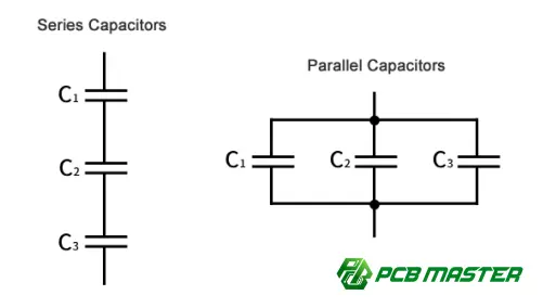
What Are Series and Parallel Capacitor Circuits?
Capacitors store electrical energy in an electric field. When multiple capacitors are connected, their electrical behavior depends on whether they are arranged in series or in parallel .
The two configurations are fundamentally different:
- Parallel capacitors: Total capacitance increases.
- Series capacitors: Total capacitance decreases.
- In parallel, capacitors share approximately the same voltage.
- In series, capacitors carry the same charge under ideal steady-state conditions.
These principles are widely used in PCB design, including power supply decoupling, DC-link circuits, filtering, timing circuits, and energy storage .
Capacitors in Parallel
When capacitors are connected in parallel, their capacitances add directly:
Ctotal =C1 +C2 +C3 +…+Cn
For example, if:
- C1 =10 μF
- C2=22 μF
- C3=47 μF
then:
Ctotal =10+22+47=79 μF
The parallel combination therefore behaves like a 79 μF capacitor in terms of ideal capacitance.
Capacitors in Series
For capacitors connected in series:
1/Ctotal =1/C1 +1/C2 +1/C3 +…+1/Cn
For two capacitors, the formula can be simplified to:
Ctotal =C1 C2 (C1 +C2 )
For example, with two 10 μF capacitors:
Ctotal =10×10/(10+10)=5 μF
Therefore, two identical 10 μF capacitors in series produce an effective capacitance of 5 μF .
Series vs. Parallel Capacitors: Key Differences
| Parameter | Capacitors in Series | Capacitors in Parallel |
|---|---|---|
| Total capacitance | Decreases | Increases |
| Voltage across capacitors | Divided among capacitors | Approximately the same |
| Charge | Same ideal charge | Charge is divided |
| Equivalent capacitance | Less than the smallest capacitor | Sum of capacitances |
| Typical application | Voltage distribution, higher voltage rating | Decoupling, filtering, energy storage |
| PCB consideration | Voltage balancing may be required | Current/ESR distribution can be important |
The most important distinction is simple: parallel connection increases available capacitance, while series connection reduces effective capacitance.
How Voltage and Charge Behave
Understanding capacitance alone is not enough for practical circuit design. Voltage and charge behave differently in series and parallel configurations.
Voltage Distribution in Series Capacitors
For capacitors in series, the charge magnitude is ideally the same:
Q1 =Q2 =Q3
Since:
Q=CV
the voltage across each capacitor is:
V=Q/C
This means a capacitor with lower capacitance can experience a higher voltage than a capacitor with higher capacitance.
For two series capacitors:
V1 =Vtotal C2 /(C1 +C2 )
V2 =Vtotal C1 /(C1 +C2 )
This voltage distribution should be considered carefully when series capacitors are used in circuits with significant DC voltage.
Voltage in Parallel Capacitors
For capacitors connected in parallel:
V1 =V2 =V3 =Vtotal
Each capacitor sees the same applied voltage.
The total charge is:
Qtotal =Q1 +Q2 +Q3
Since:
Q=CV
the resulting total capacitance is the sum of the individual capacitances.
Why Are Capacitors Connected in Parallel on PCBs?
Parallel capacitors are extremely common in PCB power systems.
For example, a designer may place:
- a bulk electrolytic capacitor,
- a polymer capacitor,
- and several ceramic capacitors
around a power IC.
Although their nominal capacitances add, their ESR, ESL, frequency characteristics, and physical placement can be very different.
This allows the capacitor network to provide effective filtering across a broader frequency range.
Example: Power Supply Decoupling
Suppose a PCB uses:
- 100 μF bulk capacitor
- 10 μF ceramic capacitor
- 0.1 μF ceramic capacitor
The nominal capacitance is:
Ctotal =100+10+0.1=110.1 μF
However, a real PCB does not behave like an ideal 110.1 μF capacitor across all frequencies.
The smaller ceramic capacitor may provide a much lower impedance at high frequencies because of its lower parasitic inductance and ESR.
Therefore, capacitor selection should consider impedance versus frequency—not capacitance alone.
Why Are Capacitors Connected in Series?
Series capacitors are less common for ordinary PCB decoupling but can be useful in specific applications.
Common reasons include:
- Increasing the effective voltage rating
- Creating a specific equivalent capacitance
- AC coupling
- Voltage-balancing networks
- Specialized power electronics circuits
For example, two capacitors with the same capacitance connected in series have half the nominal capacitance but, under appropriate conditions, can provide a higher overall voltage capability than either individual capacitor.
However, designers must not simply add voltage ratings and assume the result is automatically safe.
Leakage-current differences can cause unequal voltage sharing , particularly with electrolytic capacitors. Voltage-balancing resistors may therefore be required in some applications.
Practical PCB Design Considerations
When series or parallel capacitors are used on a PCB, the circuit should be evaluated beyond the basic capacitance equations.
1. ESR
Equivalent Series Resistance (ESR) affects:
- ripple voltage
- power dissipation
- transient response
- capacitor heating
For a capacitor carrying RMS ripple current:
Ploss =I2RMS×ESR
A lower ESR can therefore reduce resistive losses.
2. ESL
Equivalent Series Inductance (ESL) becomes particularly important at high frequencies.
Even a capacitor with excellent nominal capacitance can become less effective at high frequency because its parasitic inductance increases impedance.
This is one reason why PCB layout and capacitor placement are critical in high-speed and switching circuits.
3. Capacitor Type
Different capacitor technologies have different electrical characteristics.
| Capacitor Type | Typical Strength | Important Consideration |
|---|---|---|
| Ceramic | Low ESR/ESL, high-frequency decoupling | DC bias can reduce effective capacitance |
| Electrolytic | High capacitance, bulk energy storage | Higher ESR and limited lifetime |
| Polymer | Low ESR, good ripple performance | Cost and voltage limitations |
| Film | Stability and low loss | Larger physical size |
A practical PCB design may therefore use multiple capacitor technologies in parallel rather than relying on a single capacitor type.
Common Mistakes When Combining Capacitors
Mistake 1: Adding Series Capacitance
A common error is assuming that two 10 μF capacitors in series produce 20 μF.
They actually produce:
Ctotal =5 μF
for ideal identical capacitors.
Mistake 2: Assuming Parallel Capacitors Have Identical Performance
Two capacitors with the same nominal capacitance can have very different:
- ESR
- ESL
- ripple-current ratings
- temperature characteristics
- DC-bias behavior
- self-resonant frequencies
Therefore, nominal capacitance is only one part of capacitor selection .
Mistake 3: Ignoring Voltage Sharing
Series capacitors do not necessarily divide voltage perfectly equally.
Differences in leakage current, capacitance tolerance, temperature, and aging can change the voltage distribution.
Mistake 4: Ignoring PCB Layout
A capacitor placed several centimeters away from a switching IC may provide much less effective high-frequency decoupling than a capacitor positioned close to the relevant power and ground pins.
The interconnect itself becomes part of the electrical circuit.
Series vs. Parallel: Which Configuration Should You Use?
The correct configuration depends on the engineering objective.
| Design Objective | Preferred Configuration |
|---|---|
| Increase total capacitance | Parallel |
| Reduce equivalent capacitance | Series |
| Improve bulk energy storage | Parallel |
| High-frequency decoupling | Usually parallel capacitor network |
| Create a higher-voltage capacitor arrangement | Series, with proper voltage balancing |
| Combine different capacitor technologies | Parallel |
| Achieve a specific equivalent capacitance | Series or parallel depending on target |
Practical Engineering Checklist
Before placing capacitors on a PCB, evaluate:
- Required capacitance
- Operating voltage
- Voltage rating and derating
- RMS ripple current
- ESR
- ESL
- Capacitance tolerance
- DC-bias characteristics
- Operating temperature
- Component lifetime
- PCB placement
- Power-loop inductance
- Capacitor self-resonant frequency
For production PCB projects, engineering file review is also useful for identifying component, layout, and manufacturability issues before fabrication.
PCBMASTER's Practical Approach to Capacitor-Based PCB Design
As a PCB and PCBA manufacturer serving applications across electronics, industrial control, communications, automotive electronics, and other industries, PCBMASTER supports projects ranging from quick-turn prototypes to advanced multilayer , HDI , flexible , rigid-flex , high-frequency , and metal-core PCBs .
Its engineering support includes free document checking , allowing engineers to review PCB files for manufacturability, performance considerations, and potential optimization opportunities before production.
For applications involving demanding power or high-speed requirements, capacitor selection should be evaluated together with PCB stack-up, power distribution, grounding, trace geometry, thermal management, and component placement rather than treated as an isolated component-selection task.
Summary and Key Takeaways
Series and parallel capacitor circuits are fundamental building blocks in electronic engineering.
The core rules are straightforward:
Parallel:
Ctotal =C1 +C2 +…+Cn
Series:
1/Ctotal =1/C1 +1/C2 +1/C3 +…+1/Cn
But professional PCB design requires more than calculating equivalent capacitance. ESR, ESL, ripple current, voltage distribution, DC bias, frequency response, thermal conditions, and PCB layout can all determine whether a capacitor network performs as expected.
For engineers designing production-ready PCBs, the goal is not simply to select the largest capacitance—it is to create a capacitor network whose electrical characteristics match the circuit's actual operating conditions .
Tags
#Capacitors #SeriesCircuit #ParallelCircuit #CircuitDesign #PCBDesign #PCBA #ElectronicsEngineering #PowerElectronics #DecouplingCapacitors #PCBMASTER #EngineeringInsights
About the Author

Carol Luo
PCB Design EngineerI'm Carol, a PCB Engineer at PCBMASTER with experience in PCB design and manufacturing engineering since 2018. I focus on translating engineering requirements into reliable PCB solutions, with expertise in stack-up design, material selection, and design-for-manufacturing (DFM). I share practical engineering insights from real-world PCB design and production experience.
Visit Carol Luo's Profile

